

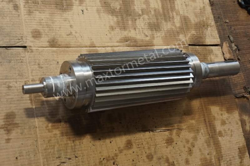
يُحمّل مركب GF-PA66 حد القطع بالطريقة نفسها التي يُحمّل بها الرمل المضخة: حيث تؤدي الألياف الزجاجية إلى تآكل الحد، ويسرع الحرارة من تليين منطقة التلامس (the land)، ويظهر أي فقدان في هندسة الشفرة فوراً على شكل جزيئات دقيقة (fines)، أو ذيول (tails)، أو طول حبيبات غير مستقر. ولهذا السبب، تتطلب شفرات تحبيب البلاستيك الدوارة التي تعمل على النايلون المقوى بالألياف الزجاجية مقاومة تآكل أعلى، وحواف دقيقة أكثر متانة، وتحكماً أكثر صرامة في انحراف الفجوة مقارنة بالدرجات غير المقواة.
ما ستحصل عليه هنا: أرقام قابلة للتطبيق، ومنطق الاختيار، وإجراءات التشغيل القياسية (SOPs)، ومؤشرات الأداء الرئيسية (KPIs) التي تترجم خيارات التصميم إلى ساعات تشغيل فعلية وحبيبات مستقرة. نحن نولي الأولوية لتحبيب الخيوط (strand pelletizing) عند 30–50% GF، والقطع الجاف، بمعدل 300–800 kg/h، مع مؤشر أداء رئيسي أساسي يتمثل في وقت تشغيل الحد الواحد ≥ 24–48 h وانحراف مستهدف في الفجوة بين الشفرة والسرير بمعدل ≤ ±2 μm/h. وحيثما توجد أرقام عامة قابلة للاقتباس (مثل فجوة وجه القالب تحت الماء)، فإننا نشير إليها مباشرة؛ وحيثما تكون المصادر الصناعية وصفية، فإننا نقدم نطاقات بدء تجريبية مع تحذيرات وطرق فحص واضحة.
من يخدمه هذا الدليل: مسؤولو المعدات والإنتاج والعمليات في خطوط التحبيب تحت الماء (UWP) وتحبيب الخيوط، بالإضافة إلى مديري المشتريات الذين يحتاجون إلى وثائق جاهزة للتدقيق لتوريد الشفرات.
حول هذا الدليل (النطاق + المؤهلات)
- النطاق: تعطي الأمثلة ونطاقات البدء الأولوية لتحبيب الخيوط عند 30–50% GF، والقطع الجاف، بمعدل 300–800 kg/h؛ بينما يتم تضمين إعدادات التحبيب تحت الماء (UWP) كسياق ثانوي.
- السلامة وأولوية الشركة المصنعة للمعدات الأصلية (OEM): استخدم دليل OEM الخاص بآلة التحبيب كوثيقة مرجعية للفجوات، وعزم الدوران، وخطوات التشغيل؛ وافصل الطاقة واتبع إجراءات الإغلاق ووضع العلامات التحذيرية (LOTO) الخاصة بالمصنع قبل إجراء أي عمل على السكاكين أو رأس القطع.
- إعداد ومراجعة: تمت المراجعة بواسطة Tommy Tang (كبير مهندسي المبيعات في Nanjing METAL؛ خبرة 12 عاماً؛ حائز على شهادات CSE و CME وحزام ستة سيجما الأخضر و PMP).
أهم النقاط
- بالنسبة لشفرات تحبيب البلاستيك لمركب GF-PA66، يُفضل استخدام ركائز مقاومة للتآكل (D2/SKD11 أو PM-HSS أو الكربيد) ودمجها مع طلاءات PVD/DLC الصلبة ومنخفضة الاحتكاك لإبطاء التشققات الدقيقة؛ واستخدم درجات مقاومة للتآكل (مثل 316/440C) للتعرض لبيئة UWP عند الاقتضاء (نظرة عامة على مقارنة MetalTek 304 مقابل 316).
- التحكم في الهندسة لا يقل أهمية عن المادة: بالنسبة لخطوط الخيوط، تعامل مع 025–0.10 mm كـ كنطاق بدء للتجربة الميدانية في المصنع لنسبة 30–50% GF، والقطع الجاف، وتوزيع الخيوط المستقر وتحقق من ذلك بمقارنته بدليل OEM ونتائج القطع؛ وبالنسبة لشفرات وجه قالب UWP،, 0.2–0.3 مم هي فجوة البدء الموثقة في دليل الإجراءات (دليل الاستبدال الآمن من MAXTOR).
- حافظ على الحد والضبط: قم بجدولة عمليات إعادة التجليخ لاستعادة التمركز المحوري وسجل انحراف الفجوة بين الشفرة والسرير بوحدة μm/h؛ واستخدم ≥24–48 h لكل حد و انحراف بمعدل ≤ ±2 μm/h بمثابة أهداف تجريبية وقم بتضييقها باستخدام بيانات الاتجاه الخاصة بك وحدود OEM (ملاحظات MAAG: “يؤدي إعادة التجليخ المنتظم والدقيق إلى تحسين جودة الحبيبات بشكل دائم...”: ماج).
- الشراء بالإثبات: اطلب شهادات المواد/المعالجة الحرارية (HT)/الصلادة/الطلاء، وأبعاد CMM، وسجلات Ra/الاستواء؛ وتحقق من ملاءمة OEM واحتفظ بقائمة مرجعية لفجوة التركيب عند كل عملية تبديل.
تحديات تآكل GF-PA66
التآكل وتشقق الحواف
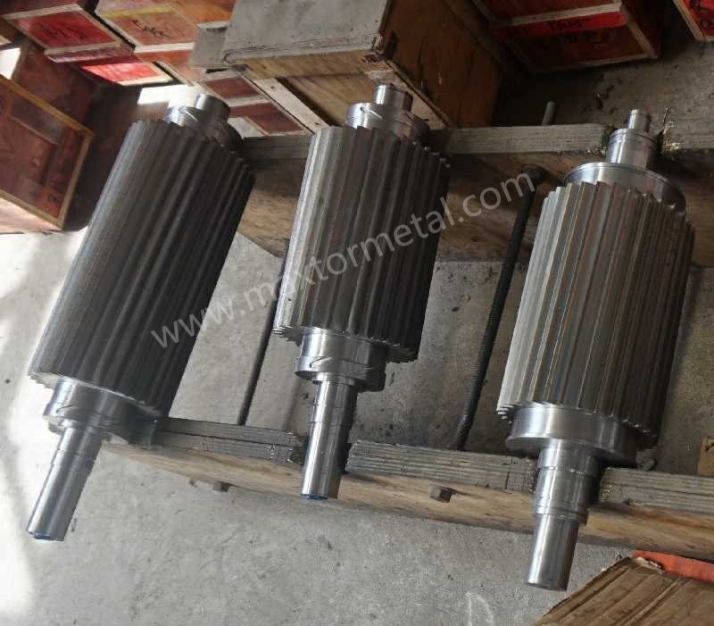
الألياف الزجاجية صلبة، وزاوية، ولا تلين. ومع مرور الخيوط بجانب حافة الدوار، تقوم الألياف بعملية تشغيل دقيق (micro-machining) لمنطقة التلامس، مما يتسبب في حدوث تشققات صغيرة تنمو لتصبح مناطق تآكل مسطحة. وتساعد الركائز الأكثر صلابة والمستقرة بالكربيد في ذلك، كما هو الحال مع أغشية PVD/DLC الكثيفة ومنخفضة الاحتكاك التي تقلل من الحفر والالتصاق. وتظهر مصادر الموردين والدراسات التي راجعها النظراء انخفاضاً في الاحتكاك والتآكل مع استخدام طبقات CrN/TiAlN المتعددة المناسبة وطلاء DLC في تطبيقات البوليمرات المملوءة، ولهذا السبب يتم دمجها بشكل متكرر مع الفولاذ المقاوم للتآكل في تطبيقات GF. انظر الأدلة حول سلوك الطلاء في أدوات البوليمر المملوء من مزودي الطلاء ودراسات الطبقات المتعددة التي راجعها النظراء، مثل مناقشة طلاءات عائلة CrN للبوليمرات المملوءة بواسطة Oerlikon Balzers وأداء طبقات CrN/TiN المتعددة في اختبارات التآكل الخاضعة للرقابة في دراسة راجعها النظراء (طلاء BALINIT MOLDENA للبوليمرات المملوءة و دراسة الطبقات المتعددة النانوية nano-CrN/TiN).
التآكل في الأنظمة تحت الماء
يضيف التحبيب تحت الماء مياهاً ساخنة ومؤكسجة—غالباً مع حمولة كلوريد من أنظمة مياه المصنع. وفي هذه الظروف، يتفوق الفولاذ 316/316L عموماً على 304 في مقاومة التآكل التنقري والتشقق الناتج عن الإجهاد والتآكل بسبب محتواه من الموليبيـدنيوم. وبالنسبة للمواد الكيميائية الأكثر قسوة أو فترات البقاء الطويلة، قد يكون استخدام درجات الأوستنيتي ذات المحتوى الأعلى من الموليبيـدنيوم أو الدرجات المزدوجة (duplex) مبرراً. توضح الأدلة العملية التي تقارن بين 304 و 316 هذه المقايضات بوضوح وهي مفيدة لاختيار المواد في الخدمة الرطبة (على سبيل المثال، مقارنة 304 مقابل 316 بواسطة MetalTek ونظرة عامة موجزة عن تآكل 304-316 بواسطة Unified Alloys).
تأثيرات انحراف الخلوص
حتى الحد المتين لن يؤدي وظيفته إذا انحرفت الفجوة بين الدوار والسرير. ويساهم في ذلك كل من التمدد الحراري، ومرونة المكونات المتراصة (المحامل، والرقاقات، وأدوات التثبيت)، والاهتزاز، ومناطق التآكل المسطحة. ومع اتساع الفجوة أو عدم انتظامها، تزداد الجزيئات الدقيقة والذيول وينحرف معامل الاختلاف (CV) لطول الحبيبات. وتؤكد أدبيات أنظمة OEM كيف يحافظ التوفر والصيانة سريعة التغيير على الهندسة، بينما تشدد إرشادات التشغيل على إعادة التجليخ الاحترافي وعزم الدوران المنضبط على أدوات التثبيت لاستعادة التمركز المحوري وإبطاء الانحراف. انظر سياق نظام M-USG من MAAG بشأن الأدوات سريعة التغيير والتوفر العالي (كتيب MAAG M‑USG) وعقليات الصيانة من أخصائيي شحذ الشفرات (نظرة عامة على خدمات الشحذ من ACE).
المواد، الصلادة، والطلاءات
الفولاذ المقاوم للصدأ/فولاذ الأدوات والأهداف
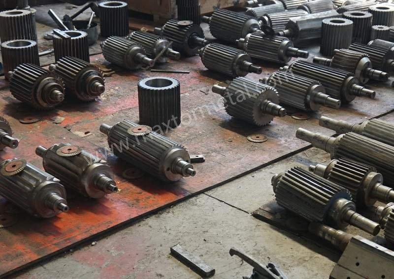
بالنسبة لأنظمة تقطيع الشعيرات التي تقطع GF‑PA66، يعد D2/SKD11 معيارًا أساسيًا شائعًا بفضل كربيدات الكروم العالية والصلابة المستقرة التي تتراوح عادةً بين أواخر الخمسينيات وأوائل الستينيات HRC عند معالجته حراريًا بشكل مناسب. ويضحي فولاذ الأدوات المقاوم للصدأ مثل 440C (وبالنسبة للتعرض للرطوبة، المكونات المتداخلة المصنوعة من 316/316L) ببعض مقاومة التآكل لصالح مقاومة الصدأ، وقد يتم تحديده لمكونات UWP أو عندما تتطلب بروتوكولات التنظيف ذلك. تضع نطاقات موردي آلات التحبيب النموذجية الفولاذ المقاوم للصدأ وفولاذ الأدوات تقريبًا من أوائل الخمسينيات إلى أوائل الستينيات HRC اعتمادًا على الفئة والهندسة؛ ويجب تنسيق نقاط الضبط الدقيقة مع بروتوكول المعالجة الحرارية وتصميم الحافة. وتدرج نظرات عامة نموذجية للموردين نطاقات معتادة لشفرات تحبيب البلاستيك تتراوح تقريبًا بين 52–65 HRC اعتمادًا على المادة والتطبيق (نظرة عامة على منتجات MAXTOR لشفرات تحبيب البلاستيك).
خيارات PM‑HSS والكربيد
يوفر فولاذ السرعات العالية المصنع بميتالورجيا المساحيق (على سبيل المثال، فئة M2 أو درجات PM ذات الفاناديوم الأعلى) كربيدات أدق وموزعة بالتساوي واحتفاظًا أفضل بالصلابة الساخنة، مما يجعلها مرشحة قوية لمهام GF الكاشطة ذات الإنتاجية العالية عندما يحد التثلم من عمر D2. ويقدم كربيد التنجستن أعلى صلابة ظاهرة ومقاومة للتآكل ولكنه يتطلب مناولة دقيقة وانضباطًا في التركيب بسبب هشاشته؛ ويمكن أن يكون الخيار الصحيح للتآكل الشديد إذا كان وقت التغيير أو برنامج إعادة الشحذ لديك محدودًا. وتعزز ملاحظات الأطراف الخارجية والموردين هذه المقايضات لسكاكين تحبيب البلاستيك وأدوات القطع المماثلة في خدمة البلاستيك الكاشط (ملاحظات صلابة سكاكين تحبيب البلاستيك من Fernite و أ نظرة عامة على المواد من Metedge).
PVD/DLC selection notes
Coatings are not a cure‑all, but the right stack extends stable hours. CrN and AlCrN families add dense, oxidation‑resistant hardness; TiN/TiAlN multilayers raise hot‑hardness and improve adhesion resistance; DLC provides very low friction to limit ploughing and buildup at the edge. Vendor data and peer‑reviewed studies show reduced wear volume and friction with these stacks in filled‑polymer or analogous wear conditions (Ionbond’s overview of PVD benefits in plastics tooling و peer‑reviewed multilayer CrN/TiN study).

Materials/coatings quick‑reference
| مادة | Typical hardness (HRC) | نقاط القوة | Cautions | Common coating pairings |
|---|---|---|---|---|
| D2/SKD11 tool steel | ~58–62 | Abrasion resistance, cost‑effective baseline | Micro‑chipping under severe fiber load if edge prep is sharp‑sharp | CrN, TiAlN, DLC for lower friction |
| 440C (stainless tool steel) | ~56–60 | Corrosion resistance, good hardness | Slightly lower wear vs D2; use where wet cleaning/UWP matters | CrN, DLC |
| PM‑HSS (e.g., M2+/vanadium PM) | ~58–64 | Fine carbides, hot hardness, toughness at edge | Cost; heat‑treat control is critical | TiAlN/CrN multilayers, DLC |
| Tungsten carbide (WC‑Co) | Very high (equivalent) | Extreme abrasion life | Brittle; mounting discipline needed | Often uncoated or thin DLC to reduce friction |
Note: Ranges above are typical supplier windows; finalize with OEM prints and heat‑treat specs. Use coating vendors’ recommendations for chemistry, temperature, and edge prep compatibility.
الهندسة، والتشطيب السطحي، والخلوص
Edge prep and Ra targets
Edge integrity starts with a controlled micro‑radius and smooth land. A too‑sharp edge chips early in GF duty; a too‑blunt edge raises cutting force and heat. Specify how the edge is prepared (honed radius, micro‑bevel, or polished land) and verify with microscopy. For the cutting land surface, target low single‑micron Ra bands and specify metrology: acceptance per ISO 4288 using stylus parameters per ISO 3274 and terms per ISO 21920‑2 (see ISO references catalog pages: ISO 4288 acceptance rules و ISO 3274 stylus instruments).
Gap and cut angles
For strand pelletizing of GF‑PA66, a practical method is to establish uniform light contact across the width, then back off evenly via eccentric or push/pull adjusters to reach a small, uniform gap.
Safety note (before any adjustment): stop the line, de‑energize, and follow plant LOTO; treat the rotor area as a pinch/entanglement hazard and allow hot components to cool. Use your OEM manual as the controlling document for adjuster sequence and torque.
For strand lines, a كنطاق بدء للتجربة الميدانية في المصنع commonly referenced in specialized setup guidance is 025–0.10 mm لنسبة 30–50% GF، والقطع الجاف، وتوزيع الخيوط المستقر; treat this as a commissioning starting point and validate with test cuts and pellet metrics, using a consistent measurement method and locations (Bay Plastics Machinery training on eccentric/push‑pull adjustment concepts).
For underwater die‑face knives, a procedural replacement guide documents 0.2–0.3 مم as a starting gap; use it alongside your OEM manual and commissioning SOPs (MAXTOR die‑face replacement guide).
Scissor mechanics matter too: helical or properly relieved geometries reduce impact, stabilize cut force, and help suppress tails and fines at a given throughput. For a deeper conceptual look at scissor vs. impact dynamics in strand cutting, see a helical‑cut explainer (helical rolling granulator blades mechanics).
UWP vs. strand specifics
Applicability (when the numeric windows do—and don’t—apply)
Use the numeric windows in this guide as commissioning starting points, not universal rules.
Applies best when:
- Strand pelletizing in the 30–50% GF range, dry cut, with stable throughput and strand distribution.
- Rotor/bed knife mounting faces are clean, flat, and burr‑free; runout and bearing condition are within OEM limits.
- You measure gaps at repeatable points (left/center/right) using a consistent method and record drift over time.
Use extra caution or expect different windows when:
- GF ≥ 50%, high mineral loading, or significant recycled content causes wider variability in melt strength and abrasion.
- The line is run intentionally hot/soft (to reduce strand breakage), which can increase smearing and change “best” clearance.
- You see non‑uniform contact marks, rapid drift, or tails/fines step‑changes—fix geometry and mechanical condition first (parallelism, mounting stack, bearings) before chasing new targets.
- Strand GF‑PA66 (our priority): focus on uniform sub‑0.1 mm gaps, a controlled micro‑radius or fine hone to resist chipping, and low‑Ra lands. Watch drift in μm/h and adjust cadence by KPI 2B.
- UWP: higher nominal die‑face gaps (0.2–0.3 mm starting range), materials and fasteners rated for hot water, and corrosion‑aware choices (316/316L on wet‑exposed parts). Coordinate blade pressure, water flow/temperature, and startup ramp to avoid gouging the die face—practical commissioning and troubleshooting guidance is covered in industry operations pieces (see Plastics Technology’s troubleshooting primer).

الصيانة ومؤشرات الأداء الرئيسية (KPIs)
نوافذ قابلة لإعادة الطحن
Regrinding is not just about sharpness; it restores concentricity and parallelism, which keeps gaps uniform and drift low. System suppliers emphasize that careful, regular regrinding permanently improves pellet quality, while professional sharpening providers outline the value of proactive schedules and proper equipment for geometry restoration (MAAG site note on regrinding and pellet quality و ACE sharpening/refurbishing capability). Define a maximum tonnage or hour threshold per edge based on your KPI 2B target and trend data; stop before wear flats grow large enough to accelerate drift or raise fines sharply.
Daily checks and balance
Adopt a short daily SOP for strand lines: clean mounting interfaces, verify fastener torque, check runout/balance, bring knives to light contact across width, back off to target gap uniformly, and record start‑of‑shift drift baselines. Log hours per edge and compute drift in μm/h from feeler‑gauge or dial‑indicator checks at repeatable locations. If drift exceeds ±2 μm/h (trial target), investigate thermal load, bearing condition, or mounting stack compliance and adjust maintenance cadence. For additional practical checks and life‑extension moves, see a maintenance guide focused on pelletizer blades (maintenance moves that cut downtime).
Quality metrics and bands
Tie regrind and setup SOPs to measurable outputs:
- Fines percentage by weight (aim for a stable low band appropriate to your downstream feeding equipment).
- Tails incidence and average tail length (watch for step changes suggesting gap non‑uniformity or a damaged edge).
- Pellet length CV (coefficient of variation) for cut stability.
- Uptime hours per edge (the headline KPI in this guide: ≥24–48 h, then push further via controlled trials).
Use these with drift in μm/h to decide whether to change geometry (edge prep, relief), material/coating, or maintenance cadence. Industry primers on pellet quality help map symptoms to root causes and preventive actions (see Plastics Technology’s path to pellet perfection).
Measurement consistency note
To make drift (μm/h) and “hours per edge” comparable across runs, measure clearance at the same left/center/right locations with the same method and gauge each time, and record the method in the log. If the method or points change, treat drift comparisons as non‑comparable.
Trial log template (what to record)
| فئة | What to log | Why it matters |
|---|---|---|
| Resin & recipe | GF% (and any mineral), moisture/drying notes, recycled content | Wear rate and chip tendency shift with fiber and moisture |
| Throughput & mechanics | kg/h, strand count, rotor rpm, knife count | Normalizes life comparisons across runs |
| Setup map | gap at left/center/right, measurement method & location, date/time | Detects non‑uniformity and setup repeatability |
| Drift KPI | gap drift in μm/h (same points, same method) | Directly links to tails/fines instability |
| Life KPI | hours/edge and tons/edge | Primary uptime outcome |
| جودة | fines %, tails incidence/length, pellet length CV | Quality impact of geometry and drift |
| Maintenance events | regrind date, stock removed, runout/balance checks, torque checks | Explains step changes in drift or quality |
Minimal A/B trial method (low effort)
Case study templates (no numbers required)
Use one template per trial so results are easy to audit later.
Template A — Material/coating change (single variable)
- Objective: improve hours/edge without increasing tails or fines.
- Change (only one): e.g., D2 → PM‑HSS, or CrN → DLC (keep geometry constant).
- Freeze: GF%, drying method, kg/h band, strand count, rotor rpm, water/air cooling, operator.
- Record: full Trial log + photo of contact pattern + note any edge chipping under microscope.
- Pass/fail: hours/edge ↑ and drift (μm/h) ↓ with no step‑increase in fines/tails/CV.
Template B — Edge prep change (single variable)
- Objective: reduce micro‑chipping and stabilize drift.
- Change (only one): edge hone radius / micro‑bevel / land polish level.
- Freeze: material, coating, and all process/mechanical variables above.
- Record: first‑hour pellet quality + 8‑hour drift trend + edge inspection photos.
- Pass/fail: fewer chips/wear flats at the same hours/edge; tails/fines trend improves.
Template C — Maintenance cadence change (single variable)
- Objective: prevent drift excursions that create tails/fines step changes.
- Change (only one): regrind trigger rule (hours/edge, tons/edge, or drift threshold).
- Freeze: blade set (material/coating/geometry) and throughput band.
- Record: downtime minutes, scrap/fines incidents, and drift trend before/after.
- Pass/fail: fewer unplanned stops and tighter drift band at similar production output.
- Freeze all variables you can (resin GF%, throughput band, rpm, cooling, operator).
- Baseline one edge with your current blade (material/coating/edge prep) and record the full log above.
- Change only one factor (e.g., coating stack or edge hone) and repeat under the same conditions.
- Compare hours/edge, μm/h drift، و fines/tails/CV; treat a step‑change as meaningful only if the setup map stayed uniform.
- Promote the winner to a longer trial and document it as a standard (SOP + acceptance criteria).
التوافق والمشتريات
قائمة التحقق من الوثائق
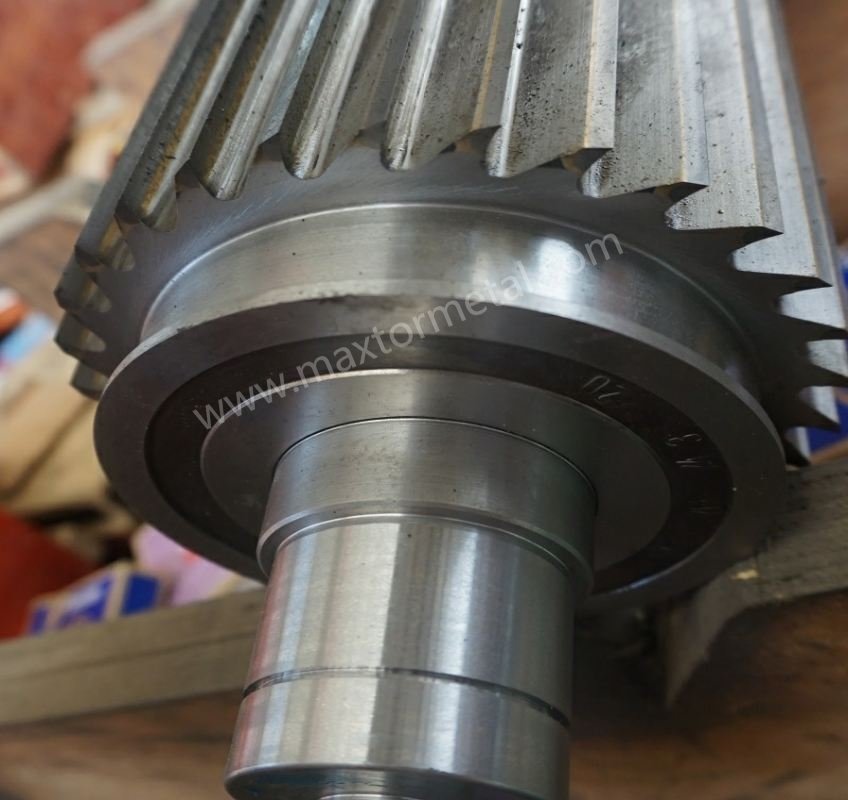
Build an audit‑ready QA pack into every RFQ and PO:
- Materials, heat‑treat, hardness, and coating certificates (grade, batch/lot, target HRC, and coating spec)
- CMM dimensional report against the OEM drawing (OD/ID, thickness, bolt circle, counterbores, squareness)
- Surface finish and flatness plan: cutting land Ra and face Ra measured and accepted per ISO 4288; include stylus parameters (per ISO 3274) and trace length
- Balance and concentricity verification for rotors or assemblies; regrind stock allowance and maximum regrind cycles; regrind SOP attached
OEM fit and tolerances
Expect OEM‑equivalent fit with tolerances documented for critical features. Keep an installation‑gap checklist with recommended starting windows (e.g., strands 0.025–0.10 mm as a trial band; UWP 0.2–0.3 mm per the cited procedural guide) and note any geometry‑specific torque or sequencing steps. A comparative overview of pelletizing blade suppliers can be useful context when aligning tolerances and coating choices across vendors (see a concise supplier and coating comparison overview).
Import logistics and service
Classify machine knives and cutting blades under HS heading 8208 (“Knives and cutting blades, for machines or for mechanical appliances”) and confirm the final 8–10 digit code per destination tariff schedule (see heading description: Flexport HS 8208 reference). Where required, seek broker confirmation or a binding classification ruling for your destination market. Standard import packs include commercial invoice, packing list, bill of lading/air waybill, certificate of origin, and any required broker entries; wooden crates should comply with ISPM‑15. Define a service SLA with lead‑time bands and communication checkpoints so maintenance windows align with delivery.
Practical example — integrating sourcing and evidence with a custom build: If you need non‑standard geometry for GF‑PA66 pelletizer blades, a supplier like ماكستور ميتال can manufacture from your drawing or a physical sample, provide material/HT/hardness/coating certificates, a CMM dimension report, and Ra/flatness records, and confirm OEM fit. Their technical articles also document safe die‑face gap settings you can adapt to your installation checklist. Use this type of QA pack and fit verification to de‑risk first‑time orders and speed up plant trials.
Author & review
تومي تانغ — مهندس مبيعات أول، Nanjing METAL صناعي
- Experience: 12 years in industrial blades and cutting tooling sourcing/support
- الشهادات: CSE، CME، الحزام الأخضر في منهجية ستة سيجما، PMP
Note: This guide is intended for engineering reference. Always follow your pelletizer OEM manual and your plant safety procedures (including LOTO) before performing any knife, cutting-head, or gap adjustments.
الخاتمة
Your design‑to‑performance path in GF‑PA66 is straightforward: pick a substrate and coating that resist abrasion (D2/PM‑HSS/carbide + CrN/TiAlN/DLC), prepare and inspect the edge and land for low Ra, set uniform gaps with documented starting windows (strands 025–0.10 mm trial لنسبة 30–50% GF، والقطع الجاف، وتوزيع الخيوط المستقر; UWP 0.2–0.3 مم per procedural guidance), and maintain the geometry through disciplined regrinding and drift tracking. When you do, on‑line hours per edge and pellet stability rise together.
الخطوات التالية
- Verify tolerances against your OEM print and metrology gear; align heat‑treat and coating specs with your resin and throughput.
- Run a controlled trial targeting ≥24–48 h per edge and ≤ ±2 μm/h drift; measure fines, tails, and pellet length CV alongside uptime.
- Lock KPIs into your SOPs, finalize your QA pack template, and schedule the next optimization loop. If you need a quick fit check or a sample built to your print, you can engage a supplier like MAXTOR METAL to validate dimensions and documentation before a full run.

 English
  Spanish
  Italian
  French
  Portuguese
  Russian
  German
  Arabic
  Hindi
Hindi  Vietnamese
  Indonesian
  Japanese
  Korean