Réponse rapide : Le flottement dynamique de la lame est le phénomène par lequel la portance hydrodynamique de l'eau de process — combinée à la contre-pression de la matière fondue — surmonte la précharge axiale de la lame et ouvre un micro-jeu de 0,03 mm ou plus à la face de la filière. Il en résulte des queues de granulés, du maculage (smearing) et des fines. La bonne réaction consiste à adapter la précharge à la vitesse de rotation (RPM) spécifique et aux conditions de film d'eau, vérifiées à chaud, plutôt qu'à augmenter simplement la force du ressort.
Le flottement dynamique de la lame est le phénomène où la résistance combinée du polymère fondu radial et la portance hydrodynamique dynamique surpassent la force de précharge axiale mécanique, ouvrant un micro-jeu de 0,03 mm ou plus à la face de la filière et permettant au polymère fondu de s'infiltrer (bleed through).
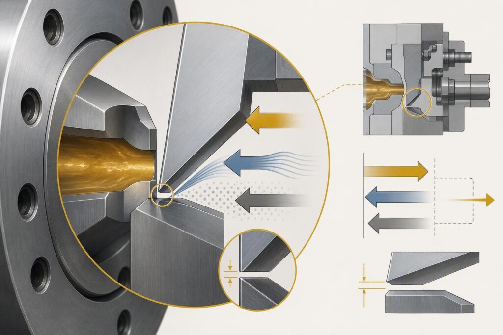
Les trois forces sont la précharge mécanique axiale qui maintient la lame contre la plaque de filière, la résistance radiale du brin de matière fondue visqueuse lors du cisaillement, et la force de poussée éloignant la lame de la plaque de filière. Cette poussée combine la portance de l'eau de refroidissement à grande vitesse avec la composante axiale de la contre-pression d'extrusion de la matière fondue, et c'est la force qui l'emporte lorsque le jeu s'ouvre.
The consequences show up as pellet defects. A gap at or above 0.03 mm produces trailing, smearing and agglomeration, and the same threshold appears in the water-ring pelletizer blade context where the working gap is described as a few mils at most (Davis-Standard, 2020). Pellet defects such as smearing and tails are the visible signature of a blade that has stopped cutting cleanly.
Cet article aborde l'équilibre des forces, la plage de fonctionnement où se forment les micro-jeux, les tolérances et la métrologie qui maintiennent le jeu fermé, les contrôles de processus qui le stabilisent, ainsi que les décisions de sélection et d'entretien des lames qui en découlent.
Principaux points à retenir
Dynamic blade float occurs when radial melt resistance plus hydrodynamic lift exceeds axial preload, opening a micro-gap of 0.03 mm or more at the die face.
The 0.03 mm figure is a threshold band with a mechanism, not a universal machine setting; confirm the working gap on your own line, hot.
Diagnose in order: check alignment and die-face condition first, then the water circuit, then the blade, because the blade is not always the root cause.
Mécanique d'équilibre des forces
Hydrodynamic lift versus preload is a contest between a force that scales with cutter speed and water flow and a force that is set cold at assembly. Plastics Technology’s underwater-pelletizing troubleshooting guide describes rotating knives acting like a ship propeller: as cutter speed rises, the axial forces from the rotating knives increase, changing the force balance needed for full knife contact (Technologie des plastiques, 2026-09-25).
En bref : blade contact depends on three competing forces — preload spring force, hydrodynamic water-film lift, and melt backpressure — and stable cutting requires preload to exceed the sum of the other two throughout the full operating cycle.
Preload and contact stiffness
Preload is the axial force that presses the blade against the die plate. The resilient blade-mounting patent describes blades mounted on Belleville or elastomeric washers that permit limited axial movement relative to the hub toward and away from the die plate, so each knife is loaded residually against the die face (US 5017119 A, 1991). That residual loading is what the lift has to beat.
Preload is not a fixed number. The cutter-hub holder patent states that the force pressing the blades toward the die plate is variable, and that a pressure spring between an annular shoulder and the piston rod can be varied by moving the piston rod to match the currently needed pressure of the blades against the die plate (US 6332765 B1, filed 2000-05-01). The same patent describes feeding the cylinder bore with regulated compressed air or regulated pressurised hydraulic fluid through a rotary transmission leadthrough in the drive-shaft bore, and an alternative embodiment using two piston heads to multiply the force applied to the pressure spring.
Two equipment makers confirm the same principle from the machine-building side, which supports the mechanism but not any specific defect rate. MAAG’s SLC underwater pelletizer is described as spring-loaded, applying continuous force toward the die plate while letting the spring be swapped to suit the application and material (Groupe MAAG, undated). Nordson BKG’s AH series describes automatic hydraulic blade-pressure adjustment, and the AH D series emphasizes a precise, repeatable and constant blade pressure (Nordson BKG, undated). Both show that blade pressure is an actively controlled variable rather than a fixed cold setting; neither publishes raw gap-versus-defect data, and pressure control alone does not prove that hydrodynamic lift exists at a given running gap.
Maxtor Metal engineers this force balance directly into blade geometry — rake angle, back clearance, and face flatness tolerances are co-specified to maintain stable contact across the full RPM range, not just at a single cold set point.
Hydrodynamic lift from process water
The lift comes from the water side. Plastics Technology’s guide identifies two water-side forces that push the cutter hub away from the die plate: the force from polymer exiting the capillaries, and the force from water pressure in the pelletizer housing acting on the drive shaft. Both act in the same direction, away from the die face.
The water-ring flow-control patent shows how deliberately that water is managed. Cooling water is supplied under controlled pressure through two fittings, and an adjustable volumetric flow rate controller sets the spray rate past the dies to maintain a continuous water ring and cascade (US 5215763 A, 1993). Flow rate is a control variable, which means lift is a control variable.
Melt backpressure at die orifices
Melt backpressure is the axial component of the force the extruding polymer exerts as it leaves the capillaries. It adds to the water-side lift rather than opposing it, which is why the two are grouped together in the thrust term.
The practical consequence is that contact is not symmetric around the die. Plastics Technology’s guide states that if axial force is too low, knives contact the die plate only at the outermost capillaries; if it is too high, knives bend and contact only at the innermost capillaries. Both extremes break full contact, and both leave part of the die face uncut.
What we see on customer lines. This is field observation rather than a controlled trial, so treat it as a pattern and not a number. Across the pelletizing lines we support, the same sequence repeats: a blade reads flat and clean at assembly, the operator logs a good cold reading, and by the second or third hour of running the pellet stream picks up fines and the die face shows smearing. When the line is pulled apart, the knife-to-die gap that was closed cold is open warm, and the die face is coldest at the outer rows where the knives stop making full contact. The pattern is consistent with the force-balance explanation above: the cold setting is not the hot setting, and the loss of contact shows up first at the edge of the die, not in the middle.
The three force components do not matter equally, and the table below maps each one to the operating conditions that make it grow and the control that keeps it in check.
Force component
Direction
What makes it grow
How it is controlled
Axial preload (spring/pneumatic/hydraulic)
Holds blade toward die plate
Assembly setting; spring rate; regulated air or hydraulic pressure
Set and verify preload; use a two-directional actuator where available
Hydrodynamic lift from process water
Pushes blade away from die face
Higher cutter speed; higher cooling-water flow and pressure; low-viscosity melt
Manage water flow and temperature; confirm gap hot
Melt extrusion backpressure at the orifices
Adds to the thrust away from the die face
Higher melt pressure and throughput; low-viscosity material
Match start-up pressure to material; reduce pressure once the process stabilises
Reading the table mechanically: preload is the only term that holds the gap closed, and all three of the other behaviours push the same way, away from the die face. That is why a gap can open even when the spring was set correctly at assembly.
Lorsque des micro-jeux seforment ≥0,03 mm
The micro-gap threshold in Maxtor Metal’s engineering guide is 0.03 mm: at or above that gap, melt bleeds through the interface and the blade starts trailing, smearing and agglomerating pellets rather than cutting them. The same guide describes the mechanism of edge damage, where insufficient axial force allows high-pressure water loops to force the blade slightly away from the die plate, the micro-gap lets polymer melt enter the interface, and the melt cools instantly and forces the blade to roll over the solidified material, rounding the cutting edge.
En bref : gaps at or above 0.03 mm allow polymer melt to enter the knife-to-die interface, producing tails and smearing; gaps above 0.05–0.08 mm typically cause doubling and chaining that require a process stop.
Observable defects and signals
Defect signatures separate into water-side and cutting-side causes. The classic pelletizing troubleshooting reference defines a tail as a little protrusion on the edge of a pellet that resembles the shape of a hockey stick on the cut edge, where the cutting apparatus has failed to make a crisp, clean cut, and notes that tails produce fines even in materials not normally susceptible to them (Technologie des plastiques, undated). The same reference defines doubles or zippers as a series of pellets attached to each other, in some cases by a thin film of polymer, either end to end or tangentially, and attributes them to too-hot process water or low water flow, while tails are generally a cutting problem, often from nicks and grooves in the die plate.
The equipment makers’ own troubleshooting guidance adds the opposite failure direction: process water too low lets polymer solidify in the die plate, while water too hot means pellets cannot cool properly and doubles or chaining follow (Pelletizing troubletshooting guide, undated). Melt temperature too low has the freeze-off effect, and too high has the same effect as hot water.
Two more signatures point at the gap itself. Why an oversized knife-to-die gap tears instead of cuts is that the blade generates micro-fragments every revolution, and re-setting cutter clearance to the specified tolerance resolves most fines cases (Technologie des plastiques, undated). Why low contact pressure produces the same smearing effect is that spring tension or pneumatic pressure drifted low lets the blade ride slightly off the surface, and raising blade pressure per manufacturer spec restores the cut.
Operating windows and thresholds
The working window is narrow. The OEM brochure confirms the knife-to-die gap is measured in thousandths of an inch, a few mils at most (Davis-Standard, 2020). The OEM brochure’s cutter-blade adjustment assembly offers gap or contact cut modes with 0.001 in (25 µm) of adjustment per turn, which is the resolution the window demands (Davis-Standard, 2020-03).
The automatic knife-adjustment patent shows the same window expressed as two control strategies: a contact mode that measures the amplitude of characteristic vibration frequencies and re-bumps the blades as they wear, or a defined running-gap mode, with a maximum contact-pressure window that can be programmed (EP 0632758 B1, granted). The patent exemplifies the gap mode with a 0.003 inch gap and a 30-minute search time, which is one machine’s setting rather than a specification.
⚠️ Avertissement The 0.03 mm figure is a threshold band with a stated mechanism, not a universal machine setting. Confirm the working gap on your own line, at temperature.
Example estimation framework
A workable framework starts from the force balance rather than from a single number. The cutter-hub holder patent describes the operating logic directly: it is sometimes necessary to start pelletizing a material of very low viscosity at a high pressure of the blades against the die plate, and after stabilization of the extrusion and pelletizing process the pressure may be reduced and pelletizing made at a lower pressure, which minimizes wear of the blades and the die plate (US 6332765 B1, filed 2000-05-01). The same patent describes removing a polymer layer forming on the cutting surfaces by a short-term increase in blade pressure, then continuing production at a gentle, lower blade pressure.
The later patent in the same family states plainly what the earlier design could not do: the spring-biased structure provides an axial force to move the cutter hub and blades toward the die plate but does not provide any force to move them axially away from the die face, and it claims a double-acting hydraulic/pneumatic system giving positive control in both directions (US 7033152 B2, granted 2006-04-25). That is the difference between setting a preload and controlling a gap.
A related patent, US20040009254A1, describes the same structural idea in more detail: a hydraulic/pneumatic mechanism that controls axial movement of the cutter hub and blades relative to the die face, letting the blades be advanced forward or retracted to control position and reduce wear on mechanical parts (US 20040009254 A1, published 2004). This is structural evidence that blade position is a dynamically controllable variable. It is a design document, not a production trial, so it does not report how much a given gap change moves a defect rate.
Maxtor Metal’s field service team uses this same start-up and stabilisation logic during blade change audits — cross-referencing the measured hot gap against the pellet defect log to confirm whether a preload adjustment or a blade replacement is the appropriate corrective action.
A peer-reviewed study adds the process-physics layer. “Numerical investigations of flow and heat transfer of polymer melt in underwater extrusion pelletizers” models the non-Newtonian flow and heat transfer of the melt, validates the model against temperature-probe and pressure-drop measurements on an industrial machine, and reports a maximum prediction error below 13% across five operating conditions (peer-reviewed CFD study; full citation available on request). The paper notes that irregular cutting between the blade and the die plate can produce fines or long tails, but it also attributes similar defects to melt temperature, die misalignment, axial or radial runout from bearing wear, and process-water temperature. Two caveats matter here: this is not a direct test of blade float versus defect rate, and the 13% figure is model prediction error, not a blade-gap measurement tolerance.
Tolérances et métrologie
Tolerances and metrology decide whether the gap you set cold is the gap you run hot. The standard wear-depth measurement method defines die wear depth as the perpendicular distance from the current die face to the plane of the original die face, measured by micrometer or rod from the outside diameter, subtracting remaining from original thickness, in the same rows of holes each inspection (Stratégie d'alimentation, 2019).
En bref : die-face flatness below 0.025 mm and rotor TIR below 0.05 mm are the two geometric prerequisites for stable blade contact — without both confirmed, preload adjustment alone cannot achieve consistent gap control.
Die-face flatness and surface condition
Flatness is the first tolerance to check. The maintenance checklist for die-face flatness gives a practical rule of thumb rather than a specification: resurface the die face when flatness deviation exceeds 0.001 to 0.002 in (approximately 0.025 to 0.05 mm) across the cutting surface, and inspect at every blade change (Davis-Standard, 2020). The source states it as a rule of thumb, and no OEM flatness specification for a polymer die-face die was found in this research.
Surface condition is specified through roughness parameters. How Ra and the cut-off wavelength are defined is set out in the Mitutoyo surface roughness guide: Ra is the arithmetical mean of the absolute values of the profile deviations from the mean line of the roughness profile per EN ISO 4287, the sampling length equals the cut-off wavelength λc, and the evaluation length generally comprises five sampling lengths (Mitutoyo, undated). The current surface-texture standard is ISO 21920-2:2021, which cancels and replaces ISO 4287:1997 (ISO, 2021-12-20). No verified Ra acceptance value for a pelletizer die face was found, so the finish callout has to come from the die drawing.
Maxtor Metal supplies a flatness and surface-finish certificate with each blade set on request, referencing the same Ra and flatness thresholds in use on the target line, so incoming inspection can be completed against a single specification sheet rather than the die drawing alone.
Rotor/hub runout (TIR) and alignment
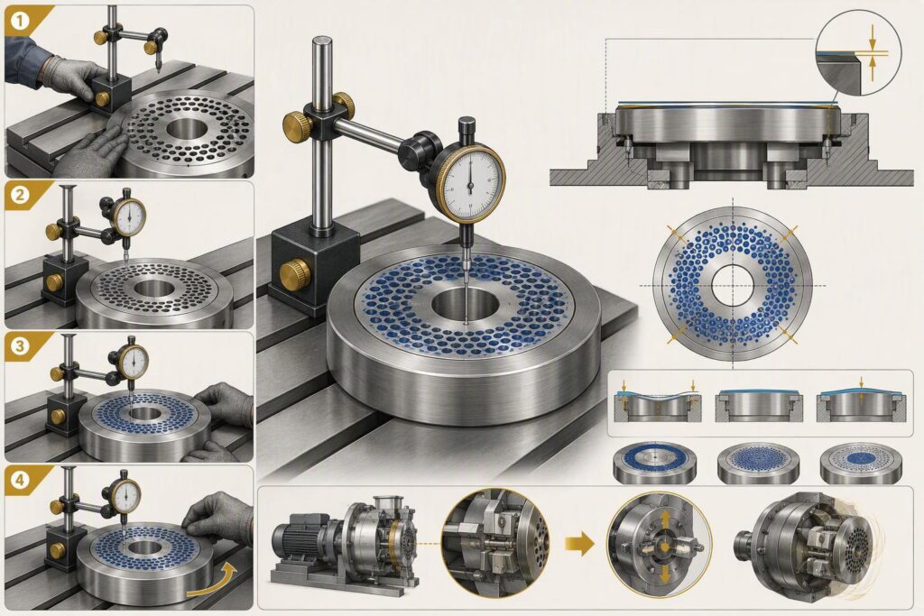
What total indicated runout actually measures is the radial deviation of cross-sectional elements about a datum axis, with a tolerance zone of two coaxial circles and a value equal to the radial distance between them, effectively the wobble of a cross-section as the part rotates (GD&T Basics, undated). Runout is measured with a dial indicator against the rotating part.
The peer-reviewed wear-analysis method confirms the wear-depth metric independently, measured at three transverse locations, the centre and the third rows of chambers from each side, except where a deep wear band requires measuring the deepest point (IJEI, Vol. 12, Issue 1). That study is a press-die wear analysis, so it supports the measurement method rather than the polymer cutting defect signatures.
A numeric TIR target of 0.02 to 0.05 mm for the cutter hub appears in one brand’s commissioning guidance, which describes it as a commonly used commissioning goal and not a specification. Treat it as illustrative and take the acceptance value from your own OEM manual.
The gap must be read at operating temperature. The OEM brochure’s cutter-blade adjustment assembly allows adjustment on the fly by hand wheel or remote pushbutton, which exists precisely because the setting has to be trimmed while running (Davis-Standard, 2020-03). No verified figure for thermal growth of the die plate or hub between cold and hot steady state was found in this research, so the point has to be made by measurement discipline rather than by a predicted expansion value.
The measurement sequence is straightforward. Record the gap cold at assembly, bring the line to thermal steady state, re-read the gap hot, and log both values against the same reference point. The resilient blade-mounting patent notes that blades may be operated in contact with the die plate or slightly spaced from it, with cushioned axial movement of each holder of around 0.0025 inch and a believed workable range of 0.0001 to 0.005 inch (US 5017119 A, 1991). That range is the patent’s own estimate, not a modern acceptance band.
Contrôles de processus et réglage
Process controls hold the gap inside the stable band once the tolerances are right. The process-control levers that hold the float in the stable band are water flow and temperature, preload setting and verification, and the start-up sequence that brings the die face to thermal balance before melt arrives (Useon, 2026-05-16).
En bref : water temperature stability and confirmed thermal balance before melt introduction are the two process variables that most reliably prevent gap formation during startup — the blade is the last variable to adjust, not the first.
Water temperature has two failure directions, and both show up as defects. The equipment makers’ own troubleshooting guidance lists process water too low, which lets polymer solidify in the die plate, and water too hot, which prevents proper cooling and produces doubles or chaining (Pelletizing troubleshooting guide, undated). The same guidance gives the chaining remedy as increasing blade pressure against the die plate, increasing blade-grind frequency, or both.
The water circuit is also a thermal circuit. Why the die plate is thermally insulated from the water side is that the die plate is fixed on the heated carrier body, and the thermal insulation ensures the melt in the die holes will not freeze, with a plate heat exchanger controlling process water temperature (ECON, undated). No verified process-water temperature setpoint range or flow-rate range was found, so the setpoints have to come from the OEM manual.
Preload setup and verification (manual/automatic)
Preload setting has moved from hand adjustment to closed-loop control. The automatic knife-adjustment patent describes a stepper-motor positioning routine with a homing step, where the operator moves the blades off the die plate and establishes the retracted position as the zero reference, after which the system positions the blades in gap mode or contact mode (EP 0632758 B1, granted).
The same patent is explicit about what earlier sensing could not do: conductivity arrangements can only indicate that a knife blade is or is not in contact with the die plate itself, and cannot accurately or effectively determine the extent or degree of contact pressure. That is the argument for measuring contact force rather than contact presence.
A published pneumatic preload setting range from the shear-slitting analogue is 60 to 90 psi (4.1 to 6.2 bar) operating, with a maximum of 100 psi and a minimum of 50 psi, and a depth-control knob that changes blade overlap by 0.004 in (0.1 mm) per click (Maxcess/Tidland, 2021-08). How a closed-loop side-force controller verifies preload is shown by the electronic knifeholder default of 5 lb side force, 0.035 in default overlap, and automatic side force correction when measured side force drifts more than ±1 lb from set point (Maxcess/Tidland, 2021-06). Both are shear-slitting values, not pelletizer die-face values, and are useful only as an analogue for how preload is set and verified.
Startup, thermal balance, and steady-state adjustments
Start-up is where the gap is most likely to open, because melt flow is low and the die face is not yet at temperature. The process-control levers include multi-zone thermal management plus a rapid-start diverter valve that maintains sufficient thermal balance at the die face even when melt flow velocity is low during startup, reducing the risk of local cooling, with outside cooling-water flow interlocked with tank water temperature (Useon, 2026-05-16).
The same source describes the preload control options in production: knives come in bevel and vertical types with either manual or hydraulic pressure setting, and with a hydraulic station the knife pressure is set on the touchscreen and the system regrinds the knife automatically per the setting time and pressure, with knife-length indication supporting wear tracking.
The hold step is what keeps the gap stable once operating pressure is reached. The double-acting patent describes independent stop valves that hold the pelletizing blades in their position after start-up and proper operating pressure has been reached, so as to insure a uniform pellet shape (US 7033152 B2, granted 2006-04-25). The same document describes a blade forward pressure circuit and an independent blade back pressure circuit, with the two opposite-side pressures insuring an optimum positioning of the pelletizer blades and avoiding unnecessary blade wear.
Two field cases, anonymised. These are observations from lines we supply blades to, rounded and reported as trends rather than as measured research data. In the first, a customer running a low-viscosity grade at high throughput had persistent fines that survived a blade change and a die resurface. The documented cold gap was at the low end of the range, but the hot reading after three hours of running was wider, and the defect rate tracked the hot reading rather than the cold one; the fix was in the water and preload side, not in the blade. In the second, a line that had been run for years with a fixed spring preload started showing smearing at start-up that cleared after an hour at rate. The pattern matched the start-up logic the cutter-hub holder patent describes: a higher pressure at start-up and a lower pressure once the process stabilises. Neither case isolates a single gap value, and neither should be read as a defect-rate curve. They are useful because they show the same thing the mechanism predicts, and because in both cases the blade was not the root cause.
Sélection et maintenance des lames
Blade selection and upkeep come after the force balance, the gap window, the tolerances and the process controls, because a harder blade does not fix a gap that opens for mechanical reasons. The blade is one variable in a system that also includes die-face condition, hub alignment and the water circuit.
En bref : blade material, edge geometry, and coating must be selected against the specific failure mode — wear, gumming, or corrosion — because optimising for one at the expense of the others shifts the failure mode rather than eliminating it.
Edge geometry, materials, hardness, and coatings
Edge geometry sets how the blade meets the die face. The resilient blade-mounting patent describes cutting edges positioned at a negative rake angle with respect to the axis of rotation and tilted at a tilt angle with respect to the die plate surface, with the cutting edge at the same angle as the tilt angle providing a self-sharpening edge, and the negative rake angle pulling the cut pellet away from the extruded strand (US 5017119 A, 1991).
Materials and hardness are a trade-off rather than a ranking. The heat-treatment window for an abrasion-resistant blade grade is illustrated by the CPM 9V datasheet, which gives an aim hardness of 54 to 56 HRC at 2050 °F austenitize plus triple temper, with toughness and wear resistance trading off against austenitizing temperature (Niagara Specialty Metals / CPM, 2021). No independent datasheet was found for the D2, M2, 420 or Stellite grades, so their hardness ranges rest on vendor technical data.
The practical question is not which grade is best in general, but which grade fits the failure the line is actually seeing. The table below maps common failure modes to the blade-side response and to the non-blade checks that must come first.
Failure mode
Likely root cause
Blade-side response
Non-blade checks first
Fines with clean geometry
Gap drifting open, or die-face wear
Confirm edge angle and sharpness; consider a tougher grade if chipping is present
Die flatness, hub runout, hot-gap reading
Tails or smearing
Edge tearing, often from die nicks or a gap at the interface
Re-dress or replace; verify edge rake angle
Die-face condition, preload verification
Edge chipping or rounding
Melt entering the gap and freezing, then rolling the edge
Harder and more wear-resistant grade
Gap opening for mechanical reasons, water circuit
Short blade life
Abrasive filler or contaminated melt
Higher wear-resistance grade or coating
Melt cleanliness, die condition, alignment
The logic follows one rule: fix the mechanism before the metallurgy. A harder grade does not close a gap that opens because radial melt resistance plus hydrodynamic lift exceeds preload, and it trades away impact toughness on thin blades and variable loads. Coatings act on wear, not on position, so they belong in the same row as hardness: useful once the gap is stable, not a substitute for getting it stable.
Maxtor Metal’s blade recommendation process starts from the failure mode table above: before specifying a grade, the team asks which row the line is in — fines, tails, chipping, or short life — because the answer determines whether a grade change, a coating, or a process adjustment is the right lever.
Coatings and surface treatments
Coating choice is a wear question, and wear is downstream of the force balance. A coating raises surface hardness or lowers friction, which helps when the failure is abrasive or adhesive wear on a correctly seated blade. It does not change the preload, the lift, or the gap, so it cannot rescue a blade that is riding off the die face. Where a line runs abrasive filled polymer or sees short blade life after the gap and alignment checks come back clean, a coating or surface treatment is the next lever to evaluate. No verified comparative coating-wear data for pelletizer blades was found in this research, so the callout should come from the grade datasheet and the supplier’s test data.
Sharpening cycles are triggered by condition rather than by a fixed interval. The equipment makers’ own troubleshooting guidance gives the chaining remedy as increasing blade pressure against the die plate, increasing blade-grind frequency, or both, and notes that most pelletizer manufacturers fit self-sharpening blades (Pelletizing troubleshooting guide, undated).
The automatic knife-adjustment patent describes the wear mechanism that drives the cycle: as the blades wear, the amplitude of the vibration decreases and the system adjusts or bumps the blades to reach the contact signal at the bump time (EP 0632758 B1, granted). That is a condition-based trigger rather than a calendar one.
No verified fastener torque values for pelletizer blade or knife-holder bolts were found, and no OEM universal resharpening interval in hours. The trigger logic is what the sources support: fines, tails, irregular shape and ammeter rise.
Vendor capabilities and quality assurance
Quality assurance for blades and dies runs on measurement rather than on claims. The ASTM fines-measurement method covers fine particles adhered on plastic pellets or granules, uses liquid wash and filtration under standard laboratory conditions, and applies to the distinct size fractions below 500 micron only (ASTM D7486-22, published 2022-12-05). The ASTM sieve-analysis method covers particle size of plastic materials in powdered, granular or pelleted forms by dry sieving, with a lower limit of measurement of about 38 μm (ASTM D1921-25, listed 2026-02-26).
Neither standard addresses blade position, die-face contact or cutter wear, so no source links a blade-control setting to a standard-measured quality value. That gap is why the practical quality check is a paired measurement: record the gap hot and cold, and record the fines and tails fraction by the two ASTM methods on the same production window.
How we apply this at Maxtor Metal, the publisher of this guide. We make replacement blades from your drawings, sketches or photos, which covers the blade-selection step above when a harder blade will not fix a gap that opens for mechanical reasons. We do not set your preload, water flow or start-up sequence, and we cannot guarantee a gap that stays closed — you still verify the float on your own line, with any blade, ours included.
FAQs:
Q : Qu'est-ce que le flottement dynamique des lames dans un granulateur ?
R : C'est le moment où la lame cesse de reposer à plat sur la face de la filière. La résistance radiale de la matière fondue et la portance hydrodynamique dépassent ensemble la précharge axiale qui maintient la lame plaques, ouvrant un micro-jeu de 0,03 mm ou plus par lequel la matière s'échappe. Des queues (trailing), du maculage (smearing) et l'agglomération des granulés surviennent en quelques tours.
Q : Pourquoi la lame du granulateur perd-elle le contact à la température de fonctionnement ?
R : Parce que l'équilibre des forces en régime permanent n'est pas le même qu'au démarrage. À froid, la face de la filière n'a pas atteint l'équilibre thermique et le débit de matière fondue est faible, de sorte que la précharge l'emporte largement. Une fois que la ligne est chaude et tourne à plein régime, le rapport entre la portance hydrodynamique et la précharge s'inverse en votre défaveur, et la lame qui était en contact à 08:00 se met à flotter à 10:00. Enregistrez le jeu en fonction du temps et de la température plutôt que de vous fier au réglage à froid.
Q : Quel jeu provoque le maculage (smearing) et les queues (tails) sur les granulés ?
R : Dès que le jeu entre le couteau et la filière dépasse environ 0,03 mm, l'arête cesse de couper et commence à arracher la matière. L'arrachage libère des micro-fragments à chaque passage et laisse sur les granulés les défauts de maculage et de queues que les opérateurs observent à la face de la filière. Considérez 0,03 mm comme une plage de seuil régie par un mécanisme physique, et non comme un réglage universel de machine : confirmez la valeur de travail par rapport au manuel de votre fabricant (OEM).
Q : Comment mesurer le jeu entre le couteau et la filière à chaud par rapport à froid ?
R : Mesurez les deux et considérez la lecture à chaud comme la valeur de travail. Les mécanismes de réglage existent précisément parce que le paramètre doit être affiné pendant que la machine fonctionne, à l'aide d'un volant manuel ou d'un bouton poussoir à distance. Aucune donnée vérifiée concernant la dilatation thermique de la plaque de filière ou du moyeu entre l'état froid et l'état stable chaud n'a été trouvée, veuillez donc consigner les deux mesures par rapport au même point de référence au lieu de prédire le changement.
Q : Puis-je éliminer les fines de granulés en augmentant la pression des lames ?
R: Généralement non, et cette tentative réduit la durée de vie de votre filière. Une pression excessive accélère l'usure de la lame et de la plaque de filière, et ne résout en rien un jeu qui s'ouvre en raison de la portance (lift). Vérifiez d'abord la planéité de la face de la filière, le faux-rond du moyeu, l'alignement et le circuit d'eau ; si le jeu continue de dériver, la solution réside dans un mécanisme de précharge contrôlant la force dans les deux directions, et non dans l'ajout de ressorts plus puissants.
Q : Quelle est la différence entre une queue (tail) et un granulé double (double) sur un granulateur ?
R : Une queue est un problème de coupe : l'arête arrache la matière au lieu de la trancher nettement, souvent en raison d'entailles ou de rainures sur la plaque de filière. Un granulé double (ou « zipper ») est un problème de refroidissement : une eau de process trop chaude ou s'écoulant trop lentement permet aux granulés de se souder entre eux avant de durcir. Les queues pointent vers l'interface de coupe, tandis que les doubles pointent vers le circuit d'eau.
Q : Comment vérifier le faux-rond du rotor (TIR) sur un granulateur ?
R : Montez un comparateur à cadran sur un point de référence fixe et faites tourner le moyeu à main, en lisant la variation totale de la section transversale par rapport à son axe de référence (datum axis). Cette distance radiale entre les deux cercles coaxiaux délimitant la surface correspond à votre TIR. Prenez la valeur d'acceptation dans votre manuel OEM ; le guide de mise en service d'une marque indique de 0,02 à 0,05 mm, mais le qualifie d'objectif courant plutôt que de spécification formelle.
Q : Une lame plus dure est-elle toujours meilleure pour la granulation ?
R : Non. Le flottement dynamique de la lame relève d'une condition d'équilibre des forces, de sorte que la dureté ne peut pas refermer un jeu ouvert par la portance (lift). Les nuances plus dures sacrifient également la résistance aux chocs au profit de la résistance à l'usure, ce qui compte beaucoup sur les lames minces et sous charges variables. Corrigez la planéité, le faux-rond, l'alignement et le circuit d'eau avant de modifier la nuance de la lame.
Conclusion
Le flottement dynamique de la lame est un problème d'équilibre des forces avant d'être un problème de lame. La combinaison de la résistance radiale de la matière fondue et de la portance hydrodynamique surmonte la précharge axiale, le micro-jeu s'ouvre à 0,03 mm ou plus, et la matière fondue qui pénètre dans l'interface se refroidit et émousse l'arête de coupe. L'approche de Maxtor Metal face à ce problème débute par la séquence de diagnostic ci-dessus : l'état de la face de la filière, l'alignement du moyeu, le circuit d'eau et la précharge sont vérifiés dans cet ordre avant de modifier la nuance ou la géométrie de la lame.
Les données disponibles ne fixent pas de chiffre universel à trois égards, et il convient de le dire clairement. Le seuil de 0,03 mm est un chiffre documenté doté d'un mécanisme explicite, la règle empirique de planéité de la face de la filière est de 0,001 à 0,002 pouces, et l'objectif de faux-rond du moyeu de coupe de 0,02 à 0,05 mm relève d'un objectif de mise en service plutôt que d'une spécification rigide. Le jeu de travail sur n'est-ce quelle ligne de production est de quelques mils au maximum et doit être mesuré à chaud.
L'ordre de diagnostic découle de ce qui précède. Vérifiez d'abord la planéité de la face de la filière et la profondeur d'usure, en utilisant la méthode de la distance perpendiculaire dans les mêmes rangées de trous à chaque inspection. Vérifiez ensuite le faux-rond du moyeu et l'alignement, à l'aide d'un comparateur à cadran placé contre la pièce en rotation. Vérifiez troisièmement le circuit d'eau, car une eau trop froide gèle la plaque de filière et une eau trop chaude génère des granulés doubles. Vérifiez quatrièmement le réglage et la vérification de la précharge, en mode jeu ou en mode contact selon les capacités de la machine. Enfin, examinez la spécification de la lame, et ce, uniquement après que les quatre premiers contrôles se soient révélés conformes.
Le même ordre qu'une séquence de décision, afin qu'un symptôme de défaut soit retracé jusqu'à sa cause avant de changer le moindre matériel :
Symptom present? Fines, tails, smearing or agglomeration seen at the die face or in the pellet stream. If none, stop.
Die-face condition. Measure flatness and wear depth in the same rows of holes. If flatness is outside your rule-of-thumb band or wear is deep, resurface or replace the die before touching anything else.
Hub runout and alignment. Read TIR with a dial indicator against the rotating part. If it exceeds the acceptance value in your OEM manual, correct alignment.
Water circuit. Confirm flow and temperature against the OEM setpoints. Too cold freezes the die plate; too hot produces doubles. Correct the circuit before judging the blade.
Preload setting. Verify preload in gap mode or contact mode as the machine supports, hot. If only the cold setting was checked, re-verify warm.
Blade specification. Only if steps 2 to 5 come back clean, review edge geometry, material and hardness. This is the last variable to change, not the first.
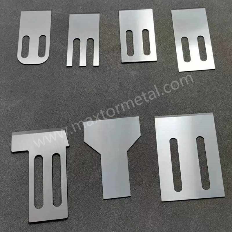
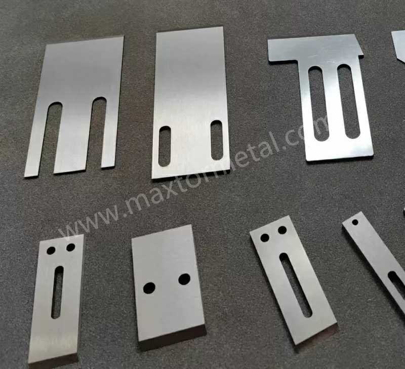
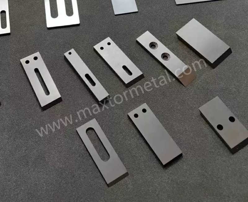
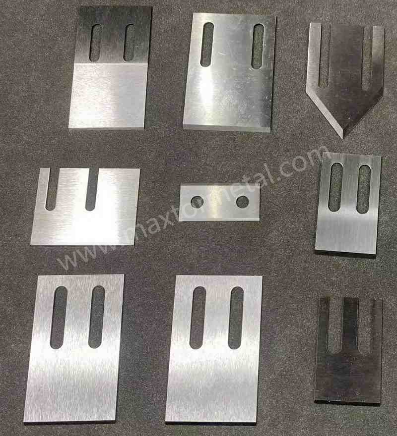
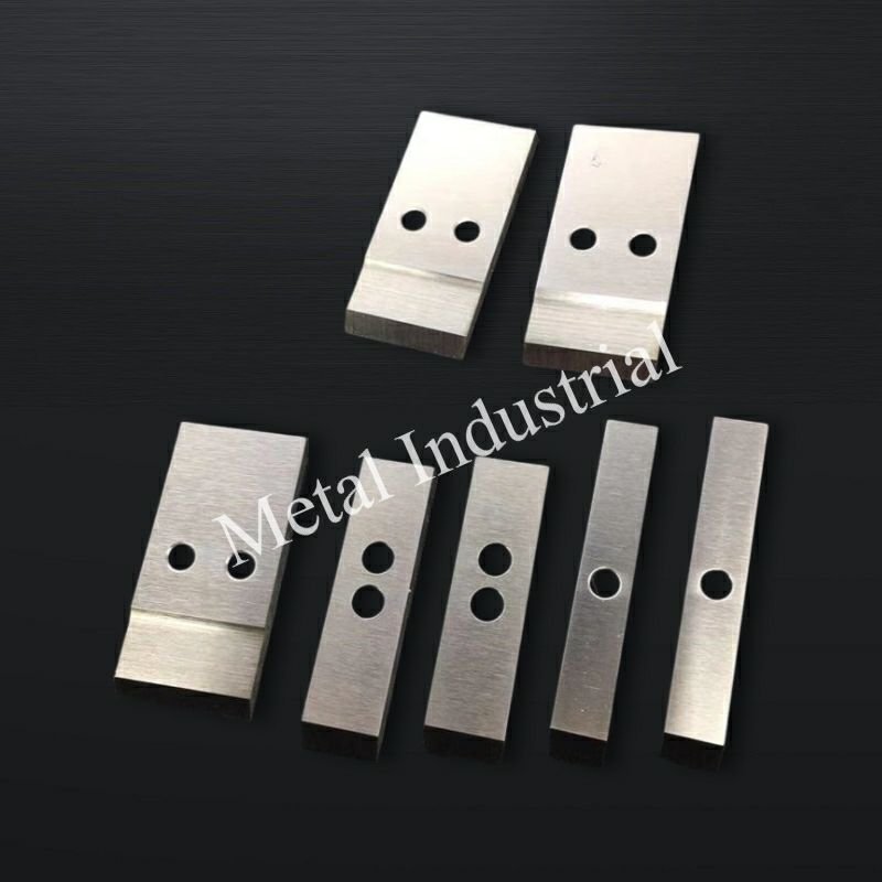
For the full range of Maxtor Metal pelletizer knife grades, dimensional tolerances, and application configurations — from thin sheet blades for water-ring systems to heavy-duty WC insert blocks for high-throughput petrochemical lines — see the plastic pelletizer knives and blades product page.
À propos de l'auteur
Jerry Chu — Technical Support Specialist, After-sales Service, Maxtor Metal.
Jerry brings 10 years of hands-on field experience across papermaking, plastic granulation, metal slitting and wood processing. On the shop floor, he is the person called in when a cut leaves burrs rather than a clean edge, or when a line is drowning in fines and dust — the pellet defects this guide is built around. His day-to-day work is turning those symptoms into a fix: checking die-face condition, hub alignment and preload before anyone reaches for a new blade.
He is a certified PMP (Project Management Professional) and CMRP (Certified Maintenance and Reliability Professional), which is why this article keeps returning to a diagnostic order and to measurement rather than to a quick parts swap.
The author’s field notes and anonymised cases in this article come from Maxtor Metal’s after-sales service work; they are observations and trends, not controlled trials.



 English
 Spanish
 Italian
 French
 Portuguese
 Russian
 German
 Arabic
 Hindi
 Vietnamese
 Indonesian
 Japanese
 Korean