If you’re responsible for equipment, process, or purchasing on a strand pelletizer (MAAG Automatik/Scheer) or you maintain underwater systems (Gala/MAAG) as a secondary line, this guide is for you. OEM‑equivalent fit is what protects uptime and pellet quality: the moment OD/ID, thickness, bolt circle, or bore/pin fits drift, you get tails, rising fines, and more frequent changeovers. Use this guide to verify your model and part numbers, then match specifications and tolerances before you buy. You’ll walk away with clear selection criteria, practical tolerance targets and verification methods, the QA documents you should demand, and lifecycle KPIs to track so you can prove performance. For search clarity, we’ll consistently refer to OEM fit rotary pelletizer blades and what “fit” really means in day‑to‑day operation.
핵심 요약
- Fit first: confirm model/part numbers and map OD/ID, thickness, bolt circle, bore/pin fits, and blade‑to‑die gap before discussing materials or coatings.
- Prove tolerances: require dimensional, runout (TIR), and, where applicable, balance documentation tied to recognized standards, not vague assurances.
- Choose geometry for the application: align material class, edge angle, and micro‑radius to resin blend severity (high‑fill, glass fiber, regrind) and die‑face condition.
- Run disciplined setup: control mounting, runout, balance, and blade‑to‑die gap with repeatable checks; verify under operating temperature.
- Track what matters: tails rate, fines %, changeover interval, and cost/ton—use them to validate OEM‑equivalent performance.
OEM Compatibility Essentials — OEM fit rotary pelletizer blades
Identify your cutter head and die interface
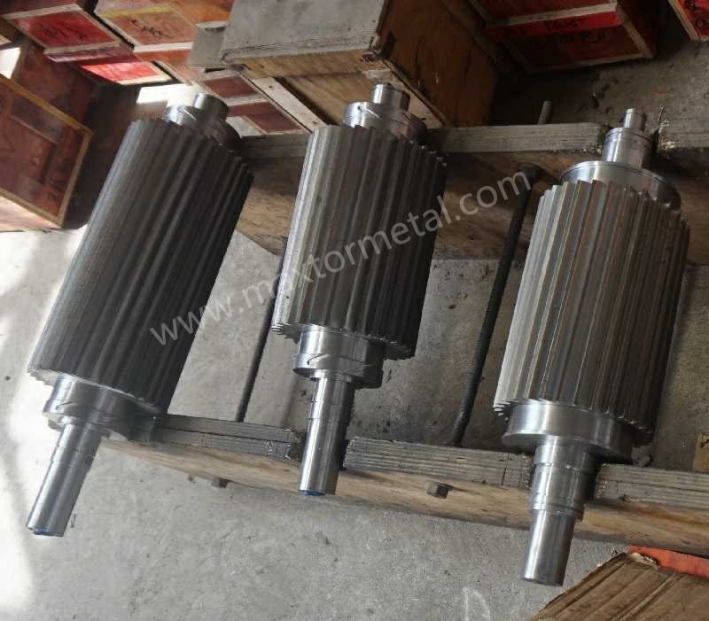
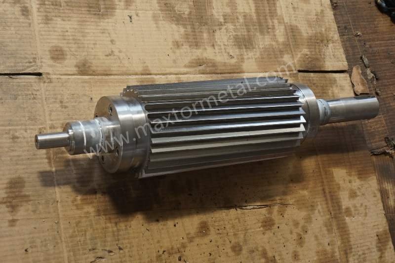
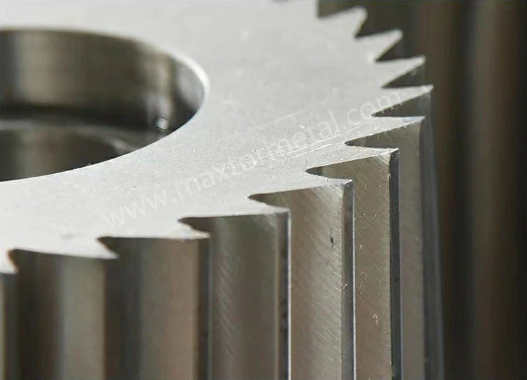
On strand pelletizers (Scheer/Automatik families like SGS/PRIMO/T‑series), the cutting action occurs as the rotating knife shears strands against a fixed bed knife. Eccentric mechanisms and robust bed‑knife supports make small misalignments visible in pellet defects; replacement blades must seat perfectly on the hub and present a flat, parallel cutting face to the bed knife. For context, Gala underwater systems position the knife against the die plate and advance it manually or automatically; the self‑aligning hub and adjustment mechanisms illustrate how precisely the blade stack‑up must interface to the die face. You can see these philosophies in MAAG and Gala literature: the Scheer S3500 and T‑series materials emphasize adjustable mechanisms and solid bed‑knife concepts, while the Gala 12S brochure shows self‑aligning hubs and controlled blade advance to the die plate (MAAG S3500 brochure; Gala 12S brochure).
Map critical dimensions and tolerance targets
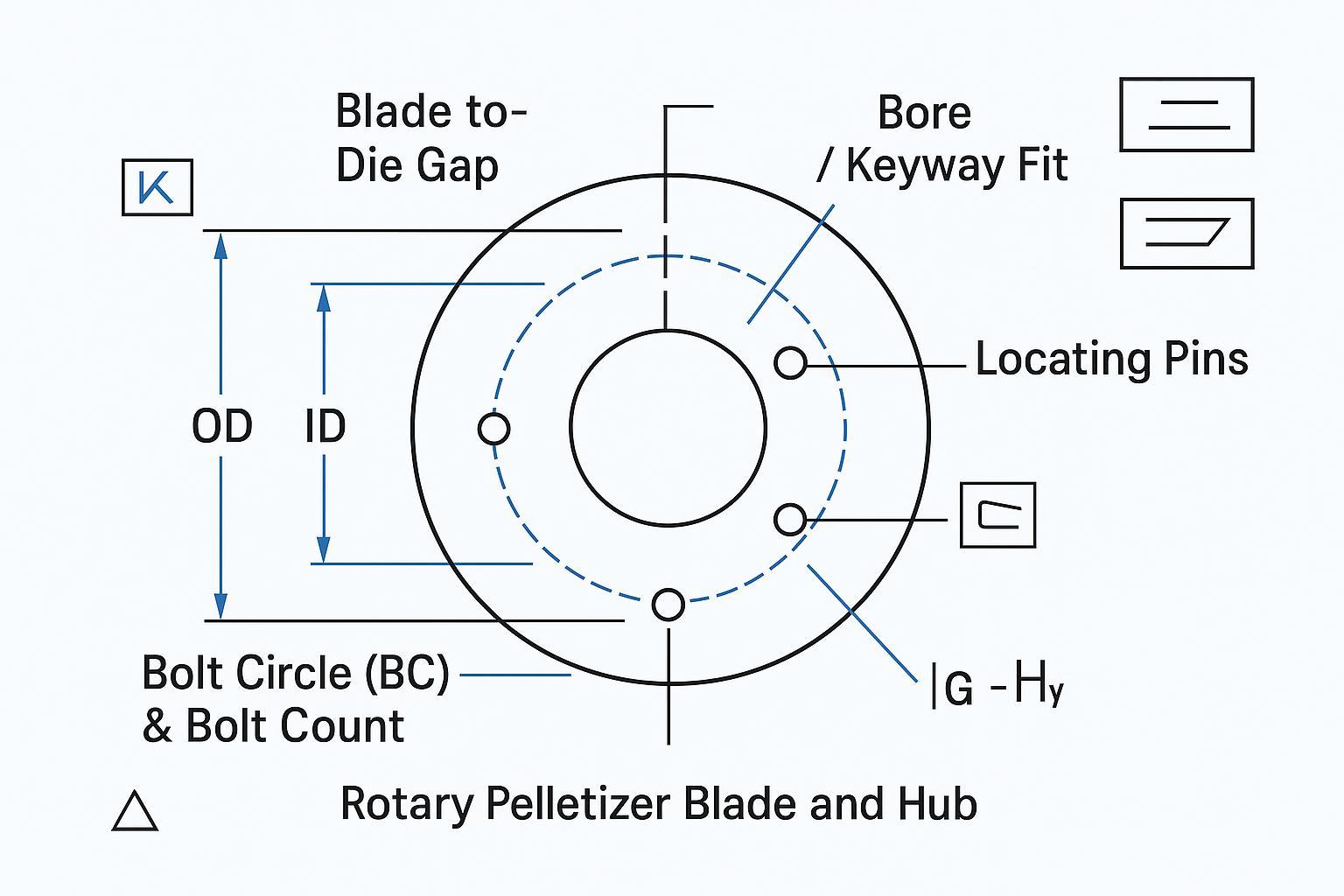
For OEM‑equivalent performance, map and verify:
- OD and ID
- Thickness (and parallelism to the seating face)
- Bolt circle diameter and bolt count
- Bore, keyway, and locating pin fits to the hub
- Blade‑to‑die (or blade‑to‑bed‑knife) gap targets and measurement method
Because OEM drawing tolerances are typically proprietary, use standards‑based acceptance. Apply GD&T to control flatness, parallelism, and runout (ISO 1101), and use ISO limits & fits (e.g., H7/g6‑style concepts) to confirm bore/shaft clearances per your hub family.
If your team needs a starting point for incoming acceptance (not an OEM claim), set “example bands” that are tight enough to prevent quality drift, then adjust once you see stable production data:
- Flatness/parallelism of seating faces: treat as a key characteristic and control on a surface plate or CMM; keep the acceptance band in the tens of microns when the design allows.
- Radial/axial runout on the assembly: measure with a dial indicator on the mounted blade OD and the seating face; aim for low TIR and investigate any jump after resharpening or lot changes.
- Bore/pin fits: document the fit intent (clearance vs. transition) and verify with calibrated bore gauges and pins; keep the same fit philosophy across lots.
중요한: these bands are only illustrative. Your final acceptance limits should be validated against your exact cutter head, RPM, and OEM manual.
A practical workflow is: First Article Inspection on CMM for OD/ID/thickness/BC/bores; surface‑plate checks for thickness parallelism; bore‑gauge/micrometer verification of fits; and dial‑indicator TIR checks on the OD and hub‑seating faces. For background on geometrical tolerancing, see the overview of ISO 1101:2017 geometrical tolerancing, and for balance/rotor concepts see the ISO 21940 rotor balancing framework.
Documentation and traceability requirements
Ask suppliers to provide a complete QA pack for every lot: EN 10204 3.1 material certificate (chemistry), heat‑treatment record, hardness test report (method noted—Rockwell/Vickers), a dimensional CMM report covering OD/ID/thickness/BC/bores/pins with GD&T callouts, surface‑finish notes for seating faces, TIR results, and—if the rotating assembly requires it—a balancing certificate aligned to the ISO 21940 framework. The documents are your parity check that an aftermarket blade meets OEM fit rotary pelletizer blades expectations without guesswork.
Materials and Edge Geometry
Material choices by application severity
Material should follow duty severity and failure mode. For general‑purpose strands with modest fillers, high‑quality tool steels can deliver stable edges and predictable resharpen cycles. As glass fiber, talc, or CaCO3 loading rises—or when regrind percentages climb—powder metallurgy (PM) high‑speed steels or tungsten‑carbide solutions often reduce wear rate and micro‑chipping. OEM and training materials reflect this gradient: MAAG’s accessory pages describe cutter‑blade materials at a high level (including stainless/tool steels and HSS families), and independent training references show solid carbide bed‑knife usage where abrasion dominates (MAAG “Cutter Blades” materials overview; BPM strand pelletizing training). Choose the class that best resists your dominant wear mechanism while keeping enough toughness to avoid edge fracturing during strand interruptions.
Edge angles, micro‑radius, and coatings
Sharper isn’t always better. Extremely acute edges can lower cutting force but are more prone to micro‑chipping in abrasive recipes; a controlled micro‑edge radius improves stability and can cut overall fines by reducing edge breakdown. Inspect edges under magnification (optical scope or profilometer) to verify that the intended micro‑radius and hone were achieved consistently across the lot. Coatings can add value when the resin/filler mix abrades or slides along the edge: physical vapor deposition options like TiN, TiCN, CrN or DLC can improve wear resistance and reduce adhesion. The right pair depends on resin family, temperature, and die‑face condition; treat coatings as a complement to, not a substitute for, base‑material suitability and geometry.
Pairing with die‑face hardness and water chemistry
Your blade’s hardness and edge form must play well with the mating surface. On strand systems, match blade toughness to the bed‑knife material and ensure both seating faces are flat and parallel; mispairing invites grooving, chatter, and dust. On underwater lines, blade contact with the die plate makes die‑face flatness and surface finish decisive; Gala documentation underscores controlled blade advance to maintain life on both components (Gala 12S brochure). Process‑water cleanliness and flow also matter in underwater service; inadequate filtration or low flow will smear cuts and elevate tails/fines, as repeatedly discussed in troubleshooting overviews from Plastics Technology (see the UWP pieces linked below). If you’re consolidating suppliers, request verifiable documentation and a compatibility check for your exact hub/die family. For example, you can ask a qualified manufacturer like 맥스터 메탈 to provide the QA pack (material, heat‑treatment, hardness, dimensional GD&T, and TIR/balance where applicable) and to confirm model compatibility based on your drawings or a sample; reputable OEMs and independent suppliers should meet the same evidence standard.
Install, Setup, and Maintenance
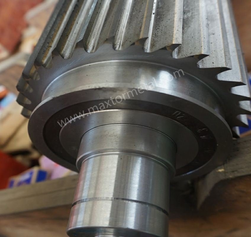
Mounting, runout, and balance checks
Start clean. Deburr and wipe the hub seating faces, confirm locating pins and bores are damage‑free, and torque fasteners in a star pattern to the machine manual’s range. Before running product, mount a dial indicator to measure radial and axial TIR on the blade OD and on the hub seating face; document peak‑to‑peak readings and compare to your acceptance band. If your assembly requires dynamic balance after resharpening or when mixing blades from different lots, align documentation and methods to the concepts defined in the ISO 21940 rotor balancing framework. Small mechanical variances multiply under speed; catching them here prevents hours of chasing fines and tails downstream.
Setting gaps and troubleshooting tails/fines
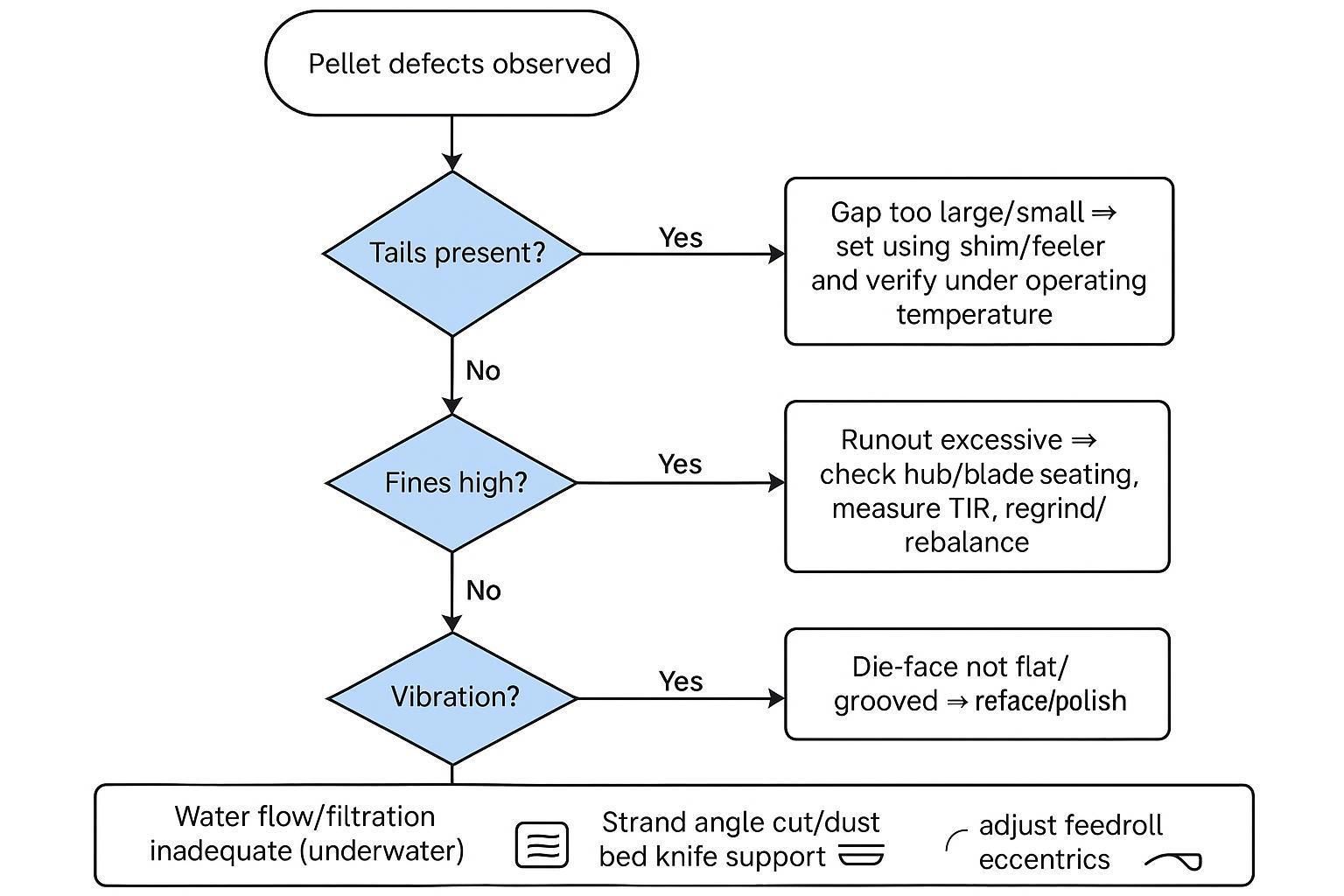
Set the blade‑to‑bed‑knife (strand) or blade‑to‑die (underwater) gap using shims/feeler gauges per your machine family, then warm to operating temperature and verify again—thermal expansion can shift contact and undo a careful cold setup.
When tails, fines, or vibration show up, treat troubleshooting like metrology, not guesswork. Use a consistent sequence so you don’t “fix” a symptom while the root cause remains:
- Confirm the contact condition at temperature
Verify your gap/contact method on a warmed machine (same RPM and water/throughput conditions used in production). If defects change with temperature, treat cold measurements as setup guidance only.
- Measure runout at repeatable indicator points
Mount a dial test indicator so the contact point is square to the surface. Record radial TIR on the blade OD 그리고 axial TIR on the seating face, rotating the assembly slowly by hand. If the reading changes after resharpening, re-check burrs on the seating faces, pin/bore damage, and torque sequence.
- Check the mating surface condition before touching the gap again
- Strand: confirm bed‑knife support rigidity and alignment; uneven support can create angle cuts that shed fines.
- Underwater: inspect the die face for grooves, non-flatness, or built-up deposits; these often create tails even when the nominal gap looks “right.”
- Validate the water side on underwater systems
Confirm filtration is operating as intended and flow is stable across the die face. Poor flow/filtration can smear cuts and inflate tails and fines.
In practice, defects map to a handful of mechanical and process causes. Persistent tails often trace to excessive gap, die‑face grooves or non‑flatness (underwater), or excessive runout. High fines usually follow edge breakdown from abrasion, angle cuts (strand) due to misalignment, or unstable contact at the interface. Multiple industry guides connect these dots; for underwater systems, Plastics Technology’s troubleshooting articles outline how die‑face condition and water flow/filtration drive pellet quality problems and how to correct them (Solving Common Problems in Underwater Pelletizing; The Path to Pellet Perfection). For strand basics around alignment and dust control, the BPM training PDF offers plain‑spoken context on eccentrics and support geometry.
Resharpen, replacement, and KPI tracking
Treat edge life as a controlled loop, not a mystery. Define resharpen acceptance (minimum thickness, edge setback limits) and track the number of grinds each blade survives while holding geometry. Pair those maintenance records with four KPIs:
- Tails rate: percent of samples where visible tails exceed your threshold (define sampling frequency and lot size).
- Fines percentage: sieve analysis (e.g., mass passing under a defined screen over a known sample weight).
- Changeover interval: hours or tons between resharpen/replace events.
- Cost per ton: (blade + resharpen + changeover downtime)/produced tons.
During a trial set, log a baseline window (e.g., one week or X tons) and then the same window post‑change; compute the deltas. When OEM fit rotary pelletizer blades are correctly specified—and you’ve held mounting/runout/gap steady—you should see lower tails/fines variance and longer intervals between service. That’s the signal to scale.
An anonymized mini case study
A strand line running abrasive formulations (high mineral filler with periodic regrind) was seeing unstable cut quality after knife changes. The plant’s team treated the change as a controlled verification exercise: they tightened incoming inspection (dimensional report + runout checks on the mounted assembly), standardized the torque sequence, and verified the cutting interface again at operating temperature.
Over the next trial window, they reported a more stable cut and fewer downstream quality interventions. The biggest operational benefit wasn’t a single “magic” setting—it was reducing mechanical drift and documenting it the same way every changeover.
| KPI | Baseline trend | After fit verification + standardized setup | How they measured it |
|---|---|---|---|
| Tails | Higher / more variable | Lower / more stable | Fixed-frequency visual sampling with a defined “tail” threshold |
| Fines | Elevated | 줄인 | Sieve analysis with a consistent screen and sample weight |
| Changeover interval | 더 짧은 | 더 길게 | Hours or tons between resharpen/replace events |
| Cost per ton | 더 높은 | 낮추다 | Blade + resharpen + downtime assumptions held constant |
Note: Results vary by resin, filler loading, and machine condition. Treat this as a method example—your own trial should lock down the measurement rule first, then compare like-for-like windows.
Quick templates you can copy into your maintenance log
First Article / Incoming inspection checklist
Use this as a “minimum evidence” checklist when receiving OEM fit rotary pelletizer blades (or any equivalent replacement):
- Part number / drawing reference and revision
- OD, ID, thickness (include parallelism of the seating face)
- Bolt circle diameter, bolt count, hole diameters, and true position callouts
- Bore diameter, keyway, and locating pin diameters and spacing
- Seating-face surface finish note (and any coating restrictions)
- Hardness report and heat-treatment record linked to the lot
- Runout report (axial and radial TIR) on the assembled hub/blade stack where applicable
Setup and verification log
Record the same items each changeover so you can correlate pellet quality changes to mechanical drift:
- Date / line / cutter head ID
- Blade lot ID and resharpen count
- Torque method and sequence used
- Radial TIR on blade OD (indicator point/location)
- Axial TIR on seating face (indicator point/location)
- Gap/contact method and check condition (cold vs hot)
- Notes: die face / bed knife condition, water filtration status
KPI tracker
Keep KPIs simple and consistent so “better” actually means something:
- Tails rate: sampling rule + threshold definition
- Fines %: sieve spec + sample weight
- Changeover interval: hours or tons
- Cost per ton: include blade, resharpen, and downtime assumptions
결론
OEM‑equivalent fit is the foundation: verify model and interface, map and prove dimensions and runout, then tailor materials and edge geometry to the application. With repeatable mounting and gap‑setting practices—and a simple KPI set—you can stabilize pellet quality and reduce cost/ton. Next steps: confirm your model/part numbers, request the full QA certificates (material, heat‑treatment, hardness, dimensional GD&T, TIR/balance), and plan a small, well‑instrumented trial set before you commit a full changeover.
Prepared by: Tommy Tang (12 years in industrial blade manufacturing and fit/inspection workflows).
폭로: This article was prepared by MAXTOR METAL. Vendor examples are provided for illustration; evaluate any qualified supplier against the same evidence standards (QA pack, dimensional verification, and documented runout/balance where applicable).
Safety note: Follow your pelletizer OEM manual for torque values, guarding, and lockout/tagout procedures. This guide does not replace machine-specific service instructions.