

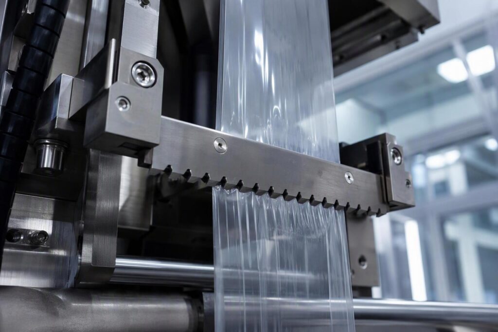
요약: There is no universal HRC value for serrated VFFS strip blades. The correct hardness window is determined by diagnosing the dominant failure mode first: tooth-root fracture (impact/fatigue mechanism) requires moving down the hardness range and switching to a tougher material route such as PM tool steel; flank notching (abrasion mechanism) supports a higher hardness window and benefits from a wear-resistant coating. At equal 61 HRC, PM grades show substantially higher fatigue and impact performance than conventional D2 due to finer, more homogeneous carbide distribution — a certificate HRC value alone cannot fix toughness. Retained austenite must be verified by XRD per ASTM E975 on an electropolished surface, not inferred from bulk hardness.
Serrated strip blades in vertical form fill seal (VFFS) machines fail in two distinct ways, and confusing them wastes money on the wrong fix. Impact-driven tooth breakage starts at the tooth root and removes material in chips; abrasion-driven notching wears the tooth flanks and tips into rounded profiles that no longer perforate film cleanly. The hardness toughness balance for serrated strip blades in VFFS is not a single number to specify, it is the output of diagnosing which of those two signatures is actually on the blade.
The diagnosis matters because the two failure modes pull hardness in opposite directions. Uddeholm’s published impact-strength curve for its PM cold work steel shows unnotched impact strength falling from roughly 90 J at 54 HRC to about 30 J at 64 HRC, so every point of hardness bought at the top of the range is paid for in impact tolerance (Uddeholm, 2024 edition). A blade specified for abrasion resistance and run on a line with jaw misalignment will chip at the tooth root instead of wearing evenly.
The blade is also only half of a cutting system. In VFFS architecture the cross-jaw pair performs sealing and cut-off together: the knife is recessed in one jaw face and actuated pneumatically while the opposing jaw carries the anvil, and built-in jaw springs absorb closure error and set a default force (Rockwell Automation, undated application note). Service practice treats the knife and anvil as a matched pair, with the rule that a new anvil is always fitted with a new knife and clearance is never adjusted to cure a cutting problem (Greener Corp., 2025-10-20). Strip stock for this class of blade is supplied in thicknesses from 0.50 mm to 2.0 mm and widths from 7 mm to 100 mm, with thickness tolerances held to ±0.01 mm to ±0.02 mm and blade-edge surface finish below Ra 0.8 µm.
엔지니어링 참고 사항: If your serrated VFFS blade specification requires documented strip tolerances, hardness distribution records, and surface finish data aligned with packaging tooling requirements, see Maxtor Metal’s reference page on 경사면 릴에 담긴 산업용 블레이드 스트립 강재 for supply specifications applicable to thin serrated strip in VFFS applications.
주요 요점
- No universal HRC value exists for serrated VFFS blades; the target comes from a failure-mode diagnosis, not a catalogue default.
- Impact strength falls steeply with hardness: roughly 90 J at 54 HRC down to about 30 J at 64 HRC on one PM grade’s published curve.
- At equal 61 HRC, manufacturing route alone changes impact behaviour, so a certificate HRC value does not fix toughness.
- Coatings address abrasion, not impact, and cannot compensate for a misaligned jaw or a worn anvil.
- Retained austenite is measured by XRD per ASTM E975 on an electropolished surface, not inferred from a hardness reading.
VFFS 톱니 칼날이 완전히 다른 두 가지 방식으로 파손되는 이유와 이를 혼동했을 때 비용이 발생하는 이유

Diagnosing tooth breakage vs notching on packaging blades comes first, because the two signatures point to different root causes and different corrective actions. Breakage is an impact and fatigue event that initiates at the tooth root and propagates; notching is a wear event that rounds the tooth tip and flank. Photograph the wear scar before changing any specification, since the scar pattern is the diagnosis.
VFFS cutting maintenance sources list the same field signatures: bag-cut tearing, edge nicking, flat spots on the blade edge, film sticking to the blade, and skewed cuts where the knife has worked loose (Vanguard Components, VFFS packaging cutter maintenance guidance). These confirm the failure vocabulary a maintenance team sees on the line, but the published pages do not give machine models, blade steel grades, measured HRC values, production cycle counts or controlled trial results, so they cannot be used to derive a percentage service-life improvement.
Impact and misalignment effects
Impact damage concentrates where the blade meets a misaligned anvil at production cycle rates. In a VFFS machine the cross-jaw pair seals and cuts in one motion: the knife sits recessed in one jaw face and is actuated pneumatically, while the opposing jaw carries the anvil, and built-in jaw springs absorb closure error and set a default force (Rockwell Automation, Application Technique: Vertical Form Fill and Seal, undated application note). Those springs have a working range. When runout or anvil wear pushes the effective gap past it, the tooth tips take the load directly.
Anvil condition drives uneven cut depth independently of blade hardness. Die-cutting guidance identifies uneven anvil surfaces, including grooves, scars, debris, lost concentricity and runout, as causes of uneven cut depth and tooling damage, and warns that a dull or damaged blade cannot be fixed by adding pressure (Royal Coat World, summarising Rotometal and Wilson guidance, 2026-08-15). Run the anvil-condition and runout check before touching the pressure setting.
Tooth breakage vs notching on packaging blades
The two signatures differ in location and geometry. Breakage removes a tooth or a tooth corner and leaves a sharp, angular fracture face at the root. Notching leaves the tooth intact but rounds its profile, so the perforation pattern degrades gradually and film tear length increases before any tooth is lost.
The ASM International consensus view frames the same tradeoff as a design principle rather than a blade-specific claim. ASM Specialty Handbook: Tool Materials identifies fracture resistance (toughness), deformation resistance and wear resistance as the three properties that govern cutting-tool design, and states that materials with very high wear resistance commonly have lower toughness, so tool selection must match the material and operating conditions rather than maximise a single property. The same source defines chipping as a localised edge failure in which small fragments break away when localised stresses exceed the tool material’s strength, and notes that higher feed rates and interrupted or unstable cuts require greater toughness (ASM International, ASM Specialty Handbook: Tool Materials, preview). The evidence boundary is that this is a general cutting-tool materials principle, not VFFS service-life data: it supports the argument that hardness and toughness trade against each other and that chipping is a stress-driven local failure, but it cannot be used to derive a chipping rate or an optimum HRC for a serrated strip knife.
Material route affects the breakage signature at a fixed hardness. In an equal-hardness comparison of K110, K360 and K390 at 61 HRC, impact energy ranked K390 PM highest, K360 ESR intermediate and K110 conventional lowest, with the conventional grade’s massive primary carbides producing what the authors described as the most rigid comportment (IMIM, Archives of Metallurgy and Materials, Vol. 3/2024, 2024).
Industry technical guidance reaches the same mechanism from the die-and-tooling side: high hardness can increase notch sensitivity, and large carbides may act as crack initiators, while toughness and ductility make crack initiation and propagation more difficult (AHSS Guidelines, tooling and tool-cracking entries, 2026). That is consistent with a sharp tooth root becoming a preferred initiation site. The evidence boundary again applies: the AHSS Guidelines address forming and stamping tooling, not VFFS film cutting, so they explain why a notch and a coarse carbide population raise cracking risk without supplying a VFFS blade number. The carbide-size difference behind the same HRC number is the mechanism: merely changing the manufacturing route alters microstructure and impact behaviour at 61 HRC, so a certificate HRC value alone does not fix a blade’s toughness (ibid., 2024). A blade that chips at the root while reading correctly on a hardness certificate is often a route problem rather than a hardness problem.
This is where the wider technical consensus lines up with the field evidence. ASM International frames the failure as a fundamental design tradeoff rather than a blade-specific defect: fracture resistance, deformation resistance and wear resistance are the properties that govern cutting-tool design, and a material optimised for maximum wear resistance will commonly give up toughness, so the correct target is a match to the material and operating conditions rather than a maximum on any one axis (ASM International, ASM Specialty Handbook: Tool Materials, preview). The AHSS Guidelines, published with contributions from steel and forming-industry specialists, reach the same conclusion from the tooling side, noting that high hardness raises notch sensitivity and that coarse carbides can seed cracks while toughness and ductility resist their initiation and growth (AHSS Guidelines, tooling and tool-cracking entries, 2026). Read together, the two references support the same practical rule the equal-hardness data implies: when teeth break at the root, treat hardness as one variable inside a material-and-geometry system, not as the single dial to turn.
Substrate, film stack, and anvil factors
Film structure changes the load the tooth sees. A laminated or metallised web presents alternating layers of different shear strength, so the tooth tip experiences a stepped load rather than a uniform one, and the tooth root accumulates the resulting fatigue cycles.
Sealing-tool geometry and machine process parameters interact as well. In a VFFS study on flexible paper-based packaging, serrated and flat sealing tools behaved differently under the same trial: the serrated tool ran at 3.8 bar surface pressure against 3.1 bar for the flat tool, across a sealing-temperature range of 100–140 °C and a dwell time of 0.5–2.0 s (BioResources, study on VFFS sealing and runnability of flexible paper-based materials). The evidence boundary matters here: those are sealing-tool experiment values, not hardness, toughness or service-life data for a steel strip knife, so they support the argument that toothed geometry and contact conditions change packaging behaviour, not a claim about tooth-chipping rates.
The knife and anvil must be treated as one consumable set. The documented service rule is to fit a new anvil with a new knife, seat both on a clean firm flat platform, avoid over-adjusting spring pressure, and treat excessive pressure as a cause of premature knife, anvil and sealing-jaw failure (Greener Corp., Solving Cutting Problems on Flow Wrappers, 2025-10-20). Replacing a blade onto a worn anvil reproduces the original failure within a shift.
소재 및 경도 범위 (Materials and hardness window)
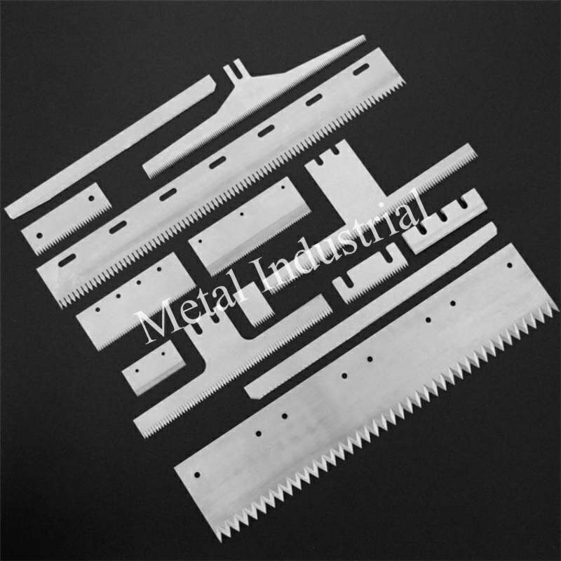
The hardness toughness balance for serrated strip blades in VFFS is set by the failure mode the line actually produces, not by a single HRC figure. Set the window from the dominant failure mode first, then choose the material route that reaches that window with the best toughness at equal hardness. That ordering is what makes the serrated VFFS blade hardness HRC range defensible in a specification.
| Service mode | Practical HRC | Rationale |
|---|---|---|
| Shearing/trimming stock under 3 mm | 60–62 | Uddeholm application table for D2-class steel |
| Short cold shears, granulator knives | 56–60 | Same table, impact risk rises |
| A2-class shearing, stock up to 3 mm | 60–62 | Rigor datasheet |
| A2-class shearing, 6–10 mm stock | 54–56 | Hardness steps down with section |
| DC53 working range | 60–62 | Vendor grade data |
| Carbon blade strip, abrasive slitting | 56–62 | Strip supplier specification |
| Stainless blade strip, edge/toughness balance | 46–56 | Strip supplier specification |
The pattern is the decision payload: the window slides downward as impact risk rises and as section thickness increases. Uddeholm’s own application data puts D2 at 60–62 HRC for shearing and trimming stock under 3 mm, and at 56–60 HRC for short cold shears, waste-plastic shredding and granulator knives, while its sister grade Rigor (A2) is listed at 60–62 HRC for stock up to 3 mm and 54–56 HRC for 6–10 mm stock (Uddeholm Sverker 21, current edition).
핵심 요약: The HRC figure is the output of a decision, not the answer. Pick the failure mode, then the window, then the grade.
PM tool steel vs D2 for serrated blades
The choice resolves on fatigue performance at matched hardness rather than on peak hardness. Conventional hot-worked D2 and PM D2 reach essentially identical hardness after 1050 °C austenitizing and 530 °C tempering, at 59.6 ± 0.5 HRC versus 59.7 ± 0.5 HRC, but the PM grade shows substantially higher high-cycle fatigue strength at that same hardness because PM processing refines and homogenizes the carbide population (Steel Research International, 2023-04-01).
That fatigue advantage is the mechanism behind the equal-hardness impact ranking. Merely changing the manufacturing route between conventional, ESR and PM changes the microstructure, carbide size and impact behaviour at the same 61 HRC, so a certificate HRC value alone does not fix a blade’s toughness (IMIM, 2024).
| Material route | Working HRC | Toughness position | Wear position | Cost position |
|---|---|---|---|---|
| Conventional D2/SKD11 | 58–61 | 기준선 | 좋은 | 최저 |
| DC53 | 60–62 | ~1.5–2x D2 at equal hardness (vendor claim) | 좋은 | Mid |
| PM cold work grade | 60–64 | Highest at equal HRC | 제일 높은 | 제일 높은 |
| A2-class | 54–62 by section | Higher than D2 at equal HRC | 낮추다 | 낮은 |
DC53’s documented working range is 60–62 HRC with Charpy V-notch impact energy of 20–30 J at room temperature and about 1.5–2x D2 toughness at the same hardness and section, which is a vendor grade claim rather than an independent test result (M. Walloys, 2026-02-25). Treat the ratio as a supplier position to verify through your own acceptance testing, not as a measured constant.
Practical HRC range for thin serrations
Thin serrated strip behaves differently from a solid die block because the tooth root has very little material to redistribute stress. The practical consequence is that the top of a grade’s hardness range, defensible on a thick shear blade, is usually too aggressive on a 0.5–2.0 mm serrated strip.
D2’s as-quenched hardness is about 63–65 HRC depending on austenitising temperature, roughly 63 HRC at 990 °C, 64 HRC at 1010 °C and 65 HRC at 1030 °C, so it must be tempered down to the working range rather than used as-quenched (Uddeholm Sverker 21, current edition). A blade delivered at as-quenched hardness has no tempering reserve and will chip at the tooth root under the first misalignment event. The tempering cycles that convert that as-quenched structure into a working window are covered in the heat treatment section.
Maxtor Metal supplies blade strip steel for VFFS serrated applications in both carbon and stainless grades — HRC 56–62 for carbon strip (SK5, C100S) and HRC 46–56 for stainless strip (420, 440C) — with thickness tolerances held to ±0.01–0.02 mm and hardness verified at multiple positions along the strip length rather than at a single end-of-coil spot check. For applications where the working HRC window sits at the lower end of the range due to impact risk, the 420 and 440C stainless grades offer a naturally lower hardness ceiling that aligns with the toughness-first specification logic described here.
Microstructure and retained austenite targets
Retained austenite is austenite that did not transform to martensite during quenching, and it matters because it is softer than martensite and metastable at room temperature. Air-hardening tool steels such as D2 and A2 commonly retain 10–20% after a conventional quench, while high-carbon, high-alloy grades including D2, M-series high-speed steel and 440C commonly retain 5–25% (Utec, 2026-04-18).
The reason the fraction is high in these grades is thermodynamic. Martensite-finish temperature for 0.8–1.0% C steels such as 52100, M2 and D2 can fall to about −45 °C to −100 °C, so a room-temperature quench stops the transformation partway and leaves austenite untransformed (Utec, 2026-04-18). For a serrated strip, the practical target is the lowest retained austenite the heat-treat route can reach without sacrificing the tempering response that produces the working hardness.
For a detailed framework on how retained austenite control — including XRD verification per ASTM E975 and the heat-treatment window for 440C-class blade strip steel — is specified and documented at the supplier qualification level, see HRC 56~58에서 440C 다이스 교체용 블레이드 검증.
How we apply this at Maxtor Metal, the publisher of this guide. We manufacture blade strip steel in grades 420, 440C, SK5 and C100S with hardness across HRC 46–62, so a hardness window set from the dominant failure mode can be matched to a strip grade rather than to a finished blade alone. The heat-treat and inspection discipline above is what makes that window repeatable on our side: each production lot is tied to a material certificate with heat number and chemistry, hardness is checked at several positions along the strip rather than at a single spot, and where a customer needs it we can supply the corresponding heat-treatment record and hardness distribution alongside the blades. What we do not do is set that window for you: the dominant failure mode on your line, the film and the machine alignment still have to be established by your own trials, and the acceptance criteria in the QA section remain yours to define and enforce, whichever supplier you buy from.
열처리와 잔류 오스테나이트 제어가 칼날의 이 빠짐(Chipping)과 마모 여부를 결정하는 방식
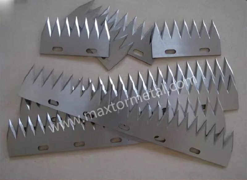
VFFS blade heat treatment and retained austenite control are one problem, not two, because the retained austenite fraction is set by the austenitising temperature, the quench and the tempering schedule together. Changing any one of the three moves the final hardness and the toughness in opposite directions.
Vacuum harden, gas quench, temper cycles
Vacuum hardening evacuates the furnace to about 10⁻⁴–10⁻⁵ mbar before heating, but the vacuum must be backed off to 10⁻¹–10⁰ mbar at austenitising temperature to prevent sublimation of manganese, chromium and cobalt from the surface and the resulting loss of hardenability (ECO Warwick / Seco Warwick, undated technical paper). Temperature uniformity of about ±5 °C across the working zone is a stated requirement for correct austenitising in the same furnace class.
D2 is hardened from a preheat of 650–750 °C at an austenitising temperature of usually 1000–1040 °C, quenched by vacuum or high-speed gas, forced air or martempering, and tempered twice with a minimum tempering temperature of 180 °C and a minimum 2 h hold, with parts tempered as soon as they reach 50–70 °C (Uddeholm Sverker 21, current edition). PM grades are quenched in vacuum with high-speed gas at a minimum overpressure of 2 bar and tempered at least twice, with three tempers at 540 °C minimum for the highest dimensional stability and ductility, and tempering below 520 °C not recommended (Uddeholm Vanadis 4 Extra SuperClean, current edition).
Cryo use and RA verification
Cryogenic treatment converts retained austenite to fresh martensite, and that conversion is why it must be followed by tempering: the newly formed martensite is untempered and brittle until the next temper cycle acts on it (Microns Hub, 2026-04-16). Placing the sub-zero step before any tempering maximises conversion before carbide precipitation begins.
The measured effect of the route is substantial. In a tool-steel experiment, low-temperature austenitising plus low-temperature tempering left 8–10% residual austenite, high-temperature austenitising at 1075 °C with triple high-temperature tempering cut it to about 4%, and adding a −150 °C cryogenic step before triple tempering reduced it to about 1%, described as almost undetectable (MTAK / Materials Testing, 2022).
Cryogenic treatment is not a free toughness win, and the direction of its effect depends on the tempering temperature. In peer-reviewed testing on a PM cold work steel, specimens tempered at 170 °C lost fracture toughness after cryogenic treatment, falling from 19.7 MPa·m¹ᐟ² conventionally to 15.5 MPa·m¹ᐟ² at −196 °C, a 21% decrease, while specimens tempered at 530 °C gained toughness, rising from 14.8 MPa·m¹ᐟ² to 17.8 MPa·m¹ᐟ² at −140 °C, a 20% increase (Yarasu et al., PMC, 2024). The same study found cryogenic treatment raised hardness 8–9% at 170 °C tempering but lowered it about 3% at 530 °C tempering.
Verification should use X-ray diffraction, not inference. ASTM E975 specifies the XRD method for retained austenite in steel with near-random crystallographic orientation, valid from 1% by volume and above, with care required above about 15 wt% total alloy content because alloying shifts peak intensities (ASTM E975-22, 2022). The measurement must be made on an electropolished surface, because grinding and machining leave a plastically deformed layer whose austenite has already transformed, and the method is near-surface only (Lambda Research, ASTM E975 practice). Magnetic saturation is faster and non-destructive but infers the fraction from lost ferromagnetic response and is affected by carbides, geometry and composition (Utec, 2026-04-18).
For the incoming material verification side of this process — including how to read a tool steel MTC, verify chemistry acceptance bands by grade, and link heat numbers to coil lot records — see Reading Tool Steel MTC for Strip Blades: A Practical QA Checklist.
Grinding burn, decarb, and uniformity
Two surface defects survive a correct furnace cycle and undo it at the grinder. Grinding burn re-austenitises and re-quenches a thin surface layer without tempering it, leaving an untempered martensite skin that is brittle and prone to micro-chipping at the tooth tip. Decarburisation removes carbon from the surface during heating and lowers the surface hardness below the core, so the tooth tip reads soft while the bulk certificate is correct.
Both defects are local, which is why bulk HRC is the wrong verification tool for them. Microindentation hardness testing under ASTM E384 covers Knoop and Vickers indenters at test forces from 9.8 × 10⁻³ to 9.8 N and is explicitly intended to quantify hardness variations over small distances, including those from decarburisation and localised softening (ASTM E384-22, 2022). A tooth-tip traverse under E384 will expose a burned or decarburised layer that a bulk reading averages away.
형상 및 엣지 가공 (Geometry and edge preparation)
Geometry decides how much of the applied load the tooth root can absorb before it cracks, and it is the cheapest variable to change. Tooth-root radius, pitch and edge condition together set the stress concentration that determines whether a correctly hardened blade chips or wears.
Tooth-root radius and pitch control
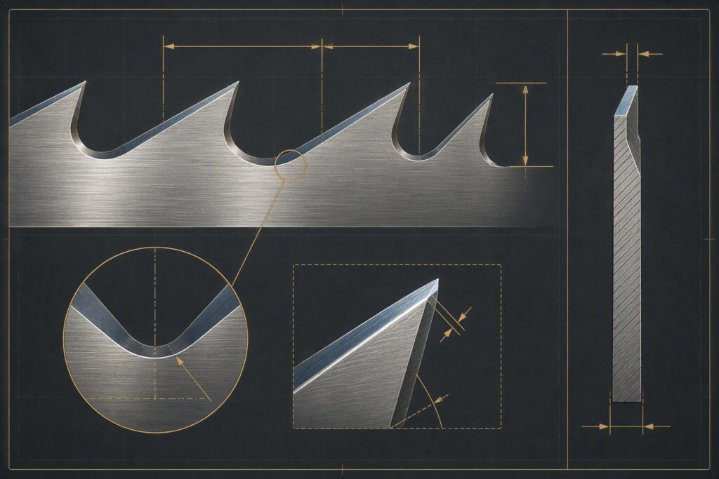
A sharp internal corner at the tooth root concentrates stress and becomes the initiation site for every impact-driven fracture. Increasing the root radius spreads the same load over more material and lowers the peak stress, which raises the impact energy the tooth can absorb without cracking.
Pitch controls how many teeth share the cut and therefore the load per tooth. A finer pitch distributes the cut over more teeth and lowers the load on each, but it also reduces the material available at each root, so pitch and root radius must be specified together rather than independently. Neither parameter has a published numeric standard for VFFS film cutting, so the defensible approach is to treat them as variables in the qualification test described in the QA section.
Edge hone and burr removal
A perfectly sharp edge is not the goal on a coated blade. Edge honing values of about 0.02–0.08 mm are the common range before coating, and honing is treated as a necessary pre-coating operation because coating material tends to accumulate on a sharp edge and form a buildup (ISCAR, undated technical guide). A blade coated without honing can end up with a thicker, irregular coating at the very edge that changes the effective tooth profile.
Burrs left from grinding or slotting are stress raisers in the same way a sharp root corner is. They also interfere with seating the blade flat against its backing, which reintroduces the misalignment the geometry was designed to tolerate.
Alignment, runout, and backing support
Runout converts a uniform cutting load into a cyclic load on one or two teeth. The anvil-condition and runout check should precede any pressure adjustment, because uneven anvil surfaces, lost concentricity and debris all produce uneven cut depth and tooling damage that no blade specification can absorb (Royal Coat World, 2026-08-15).
Backing support determines whether the strip can flex under load. A strip that is unsupported between mounting points bends instead of shearing, and the bending stress adds to the impact stress at the tooth root. Flatness and parallelism of the strip and its backing are therefore part of the hardness-toughness specification, not a separate quality concern.
필름 절단용 코팅 기술
Coatings change the wear behaviour of the tooth flank and tip, and they do nothing for impact resistance. That single distinction decides whether a coating belongs on a given blade.
When coatings help and when they don’t
A coating helps when the failure signature is notching, because notching is abrasion and a hard surface layer resists it. A coating does not help when the signature is tooth breakage, because the fracture initiates below the coating in the substrate and propagates through it regardless of what is on the surface.
A coating also cannot fix a misaligned jaw. The documented service position is that clearance must never be adjusted to cure a cutting problem and that excessive pressure causes premature knife, anvil and sealing-jaw failure (Greener Corp., 2025-10-20). Coating a blade that is chipping from misalignment produces a coated blade that chips.
Choice: DLC, CrN, TiCN, TiN
Coating selection should follow the failure mode rather than a general preference for the hardest available layer. DLC and CrN are the usual candidates where low friction against a polymer film matters, while TiCN and TiN sit in the harder, more abrasion-oriented group. The coating house guidance groups AlTiN, TiCN, TiN, ZrN, CrN and DLC in the same PVD family and gives 1–4 µm as the typical deposited thickness (Crystallume, undated applications guide).
| 코팅 | Primary benefit | Best fit | Poor fit |
|---|---|---|---|
| 다운로드 가능 콘텐츠 | Low friction, low adhesion to film | Sticky or high-friction films | High-impact, misaligned jaws |
| 크르노 | Ductile, good release | General film cutting, moderate abrasion | Severe abrasive fillers |
| 티엔(TiCN) | High hardness, abrasion resistance | Abrasive-filled films | Impact-driven tooth breakage |
| 주석 | General-purpose hardness | Baseline abrasion resistance | Where friction matters most |
Thickness and edge buildup control
Thickness is bounded by the deposition process and by the edge geometry it has to cover. PVD coatings are deposited 1–4 µm thin generally, with cutting-tool practice commonly 2–5 µm and up to 7 µm, which is the stated reason they do not meaningfully change tool dimensions (Crystallume, undated).
The edge is where thickness control actually matters. Because coating material accumulates on a sharp edge and forms a buildup, the pre-coating hone of 0.02–0.08 mm is what keeps the deposited layer uniform along the tooth profile (ISCAR, undated). Specify the hone and the coating thickness together, and inspect the tooth profile after coating rather than assuming the as-ground geometry survived deposition.
품질보증(QA) 및 검증 계획

Acceptance criteria, test design and a designed experiment turn the preceding decisions into a specification a supplier can be held to. The plan has three parts: what to inspect and accept, how to test misalignment and impact, and how to run a DOE that separates material, geometry and coating effects.
Inspection standards and acceptance criteria
Hardness is a defined test method, not a material property. ASTM E18 governs Rockwell and Rockwell superficial hardness for metallic materials and includes an annex giving the guideline for determining the minimum test-piece thickness (ASTM E18, active edition E18-25). ISO 6508-1:2023 is the international counterpart, published 13 December 2023, cancelling and replacing the 2016 edition (ISO, 2023). ASTM E18-25 also cautions that a single-location hardness result may not represent the physical properties of the whole part, which is the technical basis for multi-point inspection on a blade and for heat-treatment lot acceptance rather than a one-spot pass/fail.
Thin strip is the case where the test method itself becomes a source of error. Rockwell C is only valid when the specimen is thick enough that the deformation zone does not reach the anvil: the deformation zone extends no more than 10 times the indentation depth for a diamond indenter and 15 times for a ball indenter, stacking thin material does not fix it, and testing too-thin material can mar the anvil (NIST SP 960-5, 2001). The practical depth formulas are HRC indentation depth in mm equal to (100 − HR) × 0.002, and superficial-scale depth equal to (100 − HR) × 0.001, which is why a superficial scale is the correct choice on thin blade strip (Metkon, undated technical reference).
| Acceptance item | 방법 | 표준 |
|---|---|---|
| Bulk hardness | Rockwell, ASTM E18 / ISO 6508-1 | Within specified window; superficial scale if strip too thin for HRC |
| Tooth-tip and surface hardness | Microindentation, ASTM E384 | No soft skin from decarb or burn |
| Retained austenite | XRD, ASTM E975, electropolished surface | Per specification limit for the grade |
| Impact toughness | Notched-bar impact, ASTM E23 | Per grade and temper condition |
| Strip flatness and parallelism | Multi-point thickness measurement | Per drawing tolerance |
| Coating thickness and edge profile | Post-coating inspection | Uniform along tooth profile |
Charpy impact energy is the quantitative toughness metric behind any hardness-toughness claim, and ASTM E23 is the standard test method for notched-bar impact testing of metallic materials (ASTM E23, current revision E23-24). Note that E23 explicitly does not address impact testing below −196 °C, so it cannot be cited as covering the deep-cryogenic impact regime. Two evidence boundaries follow from that. First, E23 is a test method: it does not supply an actual impact energy for any VFFS blade, nor does it prove that a given HRC value corresponds to higher toughness. Second, a thin serrated strip may not be machinable into a standard-size Charpy specimen, so the blade body’s impact toughness should never be reported as an E23 result as such; compare witness specimens from the same heat and temper condition instead, and disclose that the specimen differs from the finished blade.
| 원천 | What it supports | What it cannot prove |
|---|---|---|
| ASTM E18-25 | Rockwell hardness method and quality-control basis | That any one hardness is the optimum for toughness |
| ASTM E23 | Notched-bar impact method and reporting framework | The actual service life of a specific VFFS blade |
| BioResources VFFS sealing study | Relationship between serrated sealing tools and packaging process parameters | Chipping rate or hardness-optimization effect of a steel strip knife |
| Packaging cutter maintenance guidance (Vanguard) | Common field cut defects and wear symptoms | Independently verified material comparison data |
Where certifications are concerned, ISO 9001 evidences a manufacturer’s quality-management system but does not substitute for hardness, toughness or life testing on a specific blade, and a supplier’s listed ISO, CE or other marks should have the certificate holder, product scope and validity checked rather than being read as performance validation for a given model.
Misalignment and impact test design
The test should reproduce the failure mode rather than a generic load. Mount the blade in a fixture that can introduce a controlled offset between the tooth tips and the anvil face, then cycle at production rate and record the number of cycles to first tooth loss and the location of initiation. A fracture at the tooth root confirms an impact mechanism; flank rounding confirms abrasion.
Run the same fixture at zero offset as the control. The difference between the offset and control results is the blade’s misalignment tolerance, and it is the number worth putting on a drawing because it tells the maintenance team how much runout the blade can absorb before the failure mode changes.
DOE for material, geometry, coatings
A designed experiment separates the three variables that interact in service. Treat material route, tooth-root radius and coating type as factors, with hardness window held constant within each material, and measure cycles to failure and cut quality as responses. This design answers the question a single-variable trial cannot: whether a coating’s benefit survives a change in root radius.
The equal-hardness evidence supports running material as a factor rather than a constant. At 61 HRC, PM, ESR and conventional routes produced different impact behaviour, so a DOE that fixes hardness and varies route will detect the effect a certificate-based specification misses (IMIM, 2024). Include a retained austenite measurement per condition so the microstructure variable is recorded alongside the mechanical result.
Field diagnosis and validation framework

The specification only becomes actionable once it is tied to a diagnosis and a controlled trial on your own line. The framework below is a suggested validation plan, not a record of a disclosed customer trial; replace the placeholders with your own factory test sheets and customer records before publishing any result.
One structural point has to be resolved first: on a VFFS machine the serrated sealing knife, the hot-cut knife and a separate cut-off knife are not necessarily the same part, and each sees a different thermal load, contact load and impact condition. Confirm which part you are specifying from the equipment drawing and the mounting position before arguing about a hardness-toughness balance for it.
When the failure signature is tooth-root fracture in a slotted blade geometry — such as grid blades used in dicer heads — the slot-root stress concentration mechanics, EDM recast layer removal, and double-temper protocol are covered in depth in Stopping Grid Blade Snapping at Slot Bottoms: Fillet Radius, EDM Integrity, and Double-Temper Controls.
To make the diagnosis repeatable, the four stages below are arranged as a decision path rather than a checklist. Each branch ends in a different specification change, and the branches are deliberately ordered so that the cheapest and most likely root causes are ruled out before hardness is touched. The following flow is a decision aid proposed from the failure-mode logic in this guide; it is not a measured dataset and should be validated against your own line records.
| Observed signature | Likely mechanism | First action | Specification lever |
|---|---|---|---|
| Sharp angular fracture at tooth root; fracture face angular, no tip rounding; fracture depth typically > 30% tooth height | Impact / fatigue | Check jaw alignment, anvil runout, clamping | Route and temper, not higher HRC |
| Rounded tooth tip and flank (tip radius grows visibly); gradual tear length increase over production hours; no angular fracture face; tip loss if present is small chips, not root breaks | Abrasion | Confirm film abrasive loading | Coating, or higher-HRC grade |
| Failure clusters after a machine change | Setup or mating part | Re-check knife-to-anvil fit | Restore alignment; no blade change |
| Soft tooth tip with correct bulk HRC | Decarb or grinding burn | Microindentation traverse per ASTM E384 | Correct grinding and heat-treat step |
The intent of the flow is to stop the common reflex of lowering hardness to cure a chip. If the signature sits in the impact or setup row, hardness is not the variable to change, and the diagnostic stages that follow show how to confirm that before any specification is revised.
The diagnostic path runs in four stages:
- Stage A – Capture the cut defect. When operators see partial seals, whiskers or irregular tearing, record the transverse position of the defect, how many consecutive bags are affected, and whether it concentrates on a few tooth tips.
- Stage B – Rule out setup and equipment. Stop the line and follow the machine’s lockout/tagout procedure. Check knife fixing, knife alignment, mating-part wear, knife-to-anvil contact and any foreign object or abnormal impact. Do not mask the defect by simply increasing clamping pressure.
- Stage C – Separate wear, chipping and fracture. After cleaning the knife, use an appropriate magnification to record tip rounding, micro-chipping, crack initiation and fracture-face features. Note whether failure concentrates at the tooth tip, the tooth root or the mounting load region, and keep an unfailed knife as a control.
- Stage D – Re-check material and heat treatment. Verify the material heat number, heat-treatment records, hardness distribution and microstructure. Where needed, run impact or other applicable toughness evaluation on witness specimens from the same batch before any controlled production comparison.
If Stage D confirms that a blade that was originally serviceable can be re-sharpened rather than scrapped, the regrind decision framework — including minimum stock removal depth, chipping depth thresholds, and lifecycle cost model — is covered in 산업용 스트립 나이프 재연마: 재연마 임계값, 폐기 기준 및 수명 주기 비용 모델.
Stage D is where a fault can be misattributed. If the chip originates from knife-to-anvil interference, assembly skew, material inclusions or a heat-treatment defect, simply lowering the hardness may not fix it.
In our own service experience, the defect pattern usually tells you where to look before you open the crate. Lines that keep a clean cut for weeks and then fail in a single cluster almost always trace back to a change on the machine side — a jaw that was re-shimmed, an anvil that was swapped without a matching knife, or a film lot that ran a little stiffer — rather than to a blade that quietly got softer in the box. The opposite pattern, gradual whiskering that spreads across the whole cut, is the one that points at the blade. That distinction is a starting hypothesis, not proof: it still has to be confirmed against the four stages above.
Setting up a traceable hardness-toughness comparison trial
Where the article needs numbers, write them as a reproducible factory trial rather than an invented customer record. The grouping below is a trial plan; the values are plan parameters, not verified field results.
| 목 | Group A – baseline blade | Group B – adjusted blade |
|---|---|---|
| 재료 | Same steel grade, same heat lot | Same as Group A |
| 열처리 | Current qualified process | Adjusted candidate process |
| Hardness target | Per current drawing and process | Set by trial result; not assumed lower |
| 톱날 형상 및 피치(Pitch) | Held identical | Held identical |
| Blade size and mounting | Identical | Identical |
| Film and machine speed | Same production conditions | Same production conditions |
| Initial inspection | Hardness, tooth form, flatness, edge quality | Same |
| Production observation | Logged by cumulative cut count | Logged to the same cut count |
If your trial log shows that changeover frequency — not blade life per se — is the primary OEE driver on the packaging line, the downtime quantification framework in OEE and Profit Gains from Reducing Coil Change Frequency provides a worked model for converting blade-change data into measurable availability loss.
Screen each group in a small batch first, then repeat with independent blades, and use several blades per group so a single knife’s performance does not decide the outcome. Define the cycle count by the specific mechanism, because a single cut action may correspond to more than one tool cycle, and record cumulative cut counts, running hours, pack counts and stop events. Log chipping, partial seals and edge wear at pre-agreed checkpoints.
If a group shows no failure, report it as “no failure up to a stated cumulative cycle count” rather than treating the checkpoint as the true service life. As an example only, a first checkpoint at 100,000 cuts and a later one at 500,000 cuts can be used to organise the trial; those are not typical VFFS blade lives or an industry standard, and real checkpoints should follow machine speed, the existing changeover interval and safety requirements.
What a hardness and toughness report should contain
| Test item | What to record | 목적 |
|---|---|---|
| Material identity | Grade, heat number, material certificate | Confirm traceability |
| 경도 | HRC at several suitable blade positions, with measurement uncertainty | Check hardness distribution and heat-treatment consistency |
| 금속조직 검사(Metallography) | Carbide distribution, grain, decarburisation, abnormal structures | Screen heat-treatment or material problems |
| Tooth form | Pitch, tip radius, root form, local notches | Rule out geometry differences |
| Toughness test | Applicable impact energy, specimen size, temperature, sampling direction | Compare material or heat-treat condition |
| Production performance | Cumulative cut count, chip count, cut-defect rate | Evaluate actual service effect |
| Failure analysis | Chip location, fracture topography, crack initiation | Separate brittle fracture, wear and assembly problems |
The most valuable evidence set for a claim like this is a traceable hardness and metallography report, a matched toughness comparison, and a VFFS cut-cycle record taken under identical production conditions. That combination is technically more convincing than an unsupported marketing figure such as “30% longer blade life” quoted without a test method or raw data.
FAQs:
What HRC should a VFFS serrated blade be?
Start from the failure mode, not from a number. A blade that wears out slowly can sit high in the martensitic range, while one that cracks or chips needs headroom below the ceiling. Published application guidance for D2-class strip puts shearing and trimming stock under 3 mm at 60–62 HRC and drops to 56–60 HRC where short cold shears and granulator knives see intermittent shock (Uddeholm Sverker 21, current edition). Treat those as brackets to test inside, not as a specification to copy.
Why do my packaging blades chip at the tooth root?
Root chipping is a fatigue and impact signature rather than an abrasive one. It usually traces back to jaw misalignment, anvil runout, or a blade running at the top of its hardness window where impact strength is thinnest. At a matched 61 HRC, conventional D2-class steel ranked below PM and ESR routes on impact energy, which means a correct hardness reading can still coexist with root chipping if the material route is wrong (IMIM, 2024).
Is PM tool steel better than D2 for serrated blades?
Only if fatigue is what kills your blades. Conventional and PM D2 land at nearly the same hardness after 1050 °C austenitizing and 530 °C tempering, 59.6 versus 59.7 HRC, yet the PM grade shows substantially higher high-cycle fatigue strength at that hardness because its carbides are finer and more evenly distributed (Steel Research International, 2023-04-01). Where flank wear dominates, the premium buys little; where teeth break off, it addresses the actual mechanism.
Can a coating stop blade chipping?
No. A coating resists abrasion at the flank and tip, and it does nothing for the substrate’s fracture resistance, so impact-driven chipping continues underneath it. Coatings also cannot compensate for a misaligned jaw, since clearance is never the variable to adjust when a cut goes wrong (Greener Corp., 2025-10-20).
How do I measure retained austenite in a blade?
X-ray diffraction per ASTM E975 is the reference method, valid from 1% by volume upward, and it needs extra care above roughly 15 wt% total alloy content (ASTM E975-22, 2022). The surface must be electropolished first, because grinding leaves a deformed layer whose austenite has already transformed and will bias the reading (Lambda Research, ASTM E975 practice). Magnetic saturation is quicker but indirect, and carbides and part geometry both shift the signal.
Can I check hardness on 0.5 mm blade strip with a standard HRC tester?
Not reliably. Rockwell C is only valid when the deformation zone stays clear of the anvil, and for a diamond indenter that zone can reach ten times the indentation depth; stacking thin strips does not correct it (NIST SP 960-5, 2001). Use a superficial scale instead, or microindentation per ASTM E384 (ASTM E384-22, 2022).
Does cryogenic treatment help VFFS blades?
It depends on the tempering temperature, and it can go either way. In peer-reviewed work on a PM cold work steel, the cryogenic step cut fracture toughness by 21% at 170 °C tempering but raised it by 20% at 530 °C tempering (Yarasu et al., PMC, 2024). Specify cryogenic treatment together with the temper schedule, never as a standalone line on the drawing.
What should I put on the drawing to lock lot-to-lot consistency?
Name the hardness window together with the test method and scale, the retained austenite limit by XRD per ASTM E975, impact testing per ASTM E23, the tooth-root radius and pitch, the pre-coating hone range, and the coating thickness. Add a misalignment tolerance figure taken from your own fixture test, because no published standard supplies a numeric clearance for VFFS film cutting. Maxtor Metal provides a drawing-review service for customers specifying serrated VFFS strip — including verification that the stated HRC window, RA limit, and strip tolerance are achievable within our production process before first shipment.
결론
The hardness toughness balance for serrated strip blades in VFFS is a specification system, not a single HRC figure, and the payoff for getting it right is measured in uptime rather than in a number on a certificate. A practical starting point is a powder-metallurgy cold work steel at 58–60 HRC: Uddeholm’s published impact-strength curve for its PM cold work steel shows the impact energy a PM grade still holds at that hardness, which is the margin that keeps a thin serration from cracking when the jaw closes slightly out of square. Where the cut is a shear on thin stock and abrasion drives wear, the window can sit higher; as section thickness grows, the same application data steps hardness down rather than up (the Rigor shearing table showing hardness stepping down with stock thickness).
The diagnostic principle in one sentence: When a serrated VFFS blade chips at the tooth root, the fix is almost never a higher-specification blade — it is jaw alignment, anvil condition, material route, or tempering schedule. When it wears at the flank, then and only then does a coating or a harder grade address the actual mechanism.
From there, validate before you commit. Confirm tooth-root radius and pitch against the film stack and anvil you actually run, then treat coatings as a finishing decision rather than a fix for a geometry or alignment problem. Lock the specification with traceable controls, because lot-to-lot consistency is what protects the changeover interval you just bought.
For a supplier, that means documented hardness bands and strip tolerances rather than a single headline figure. Maxtor Metal publishes an HRC 56–62 carbon and 46–56 stainless split with a ±0.01 mm strip tolerance, which is the level of control a staged validation plan needs to hold from reel to reel.
Start with one line, one film, and a measured baseline. Maxtor Metal provides customers qualifying serrated strip blades for VFFS applications with batch-level documentation — hardness distribution records, heat-treatment batch data, strip tolerance certificates, and RA verification results formatted for supplier audit programs. Customers at the specification stage can request the strip supply documentation package from the Maxtor Metal industrial blade strip steel in beveled reels product page before committing to a draw revision.
Three conclusions carry the argument, and they are the ones to hold onto when a specification is challenged:
- Hardness is not toughness. Hardness helps assess wear resistance, but it cannot on its own predict a tooth tip’s resistance to chipping.
- Tooth geometry and machine setup matter. Tip and root geometry and the knife-to-anvil fit change the local stress and the actual failure mode.
- Production cycles must be measured, not assumed. Blade life has to be established from a defined cycle count, repeated trials and failure records rather than inferred from a steel grade or an HRC value.
낸시 우 is a Senior Manufacturing Engineer in the Production Engineering (PE) team at Maxtor Metal, with over a decade of hands-on experience in industrial blade manufacturing. She specializes in the machining characteristics, material behavior and coating performance of common blade steels, including SKD11, 420, 440C, D2, M2 and H13, as well as powder-metallurgy steels and cemented carbide, and brings high-precision CNC grinding programming to that work. Her credentials include SME Certified Manufacturing Engineer (CMfgE), PMP, Six Sigma Black Belt and ASM International certifications.

 English
 Spanish
 Italian
 French
 Portuguese
 Russian
 German
 Arabic
 Hindi
 Vietnamese
 Indonesian
 Japanese
 Korean