- What this guide covers: metallurgical window, QA/validation, sanitation, and ROI
- Who should read: technical managers, manufacturing and process engineers
- Outcome: a data-backed path to specify and validate 440C at HRC 56–58
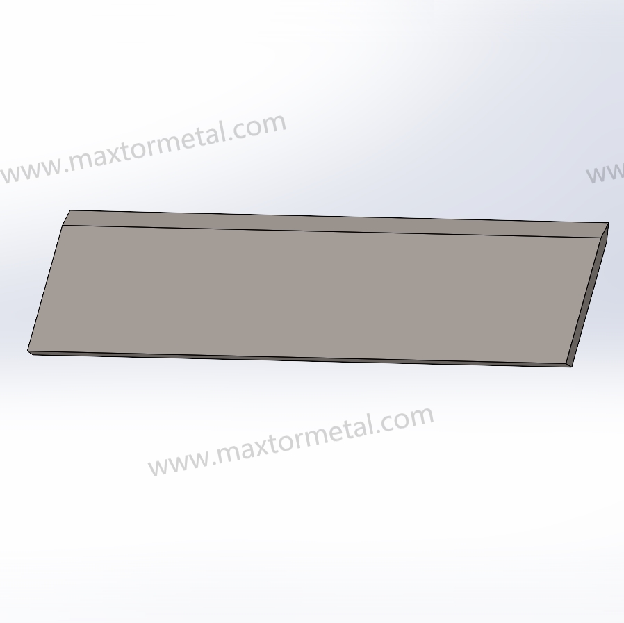
어쉘(Urschel) 스타일의 다이서 헤드는 가혹한 반복 하중(cyclic loading) 하에서 작동합니다. 밴드형 칼날이 고주파로 제품과 접촉하며, 충격의 강도는 부드러운 신선 농산물과 단단한 냉동 제품(IQF 급속 냉동 채소 및 근채류는 경화 목재에 필적하는 표면 경도를 가질 수 있음) 사이에 큰 차이가 있습니다. 절단 치수 유지 능력과 칼날 수명은 직결되어 있어, 첫 번째 냉동 사이클에서 밴드가 치핑(mẻ)되면 이후의 모든 절단에서 치수 편차가 발생합니다. 이것이 이 애플리케이션의 재료 검증이 단순한 경도 규격 설정에 그치지 않고, 라인에서 가동되는 전체 제품 믹스를 아우르며 버텨낼 수 있는 '검증된 프로세스 윈도우(validated process window)'여야 하는 이유입니다.
어쉘(Urschel) 스타일 헤드의 교체용 다이서 밴드형 칼날을 검증할 때, 440C는 흔히 '철저히 제어될 때만 통하는' 선택지입니다. 날끝(edge)을 유지할 만큼 충분히 단단하고 습한 환경에서 버틸 만큼 내식성이 우수하지만, 어설픈 열처리와 후가공은 절대로 용납하지 않습니다.
From a quality-system perspective (the way Maxtor Metal documents critical consumables), the fastest path to repeatability is to treat “440C at HRC 56–58” as a validated process window—not just a line item on a purchase order.
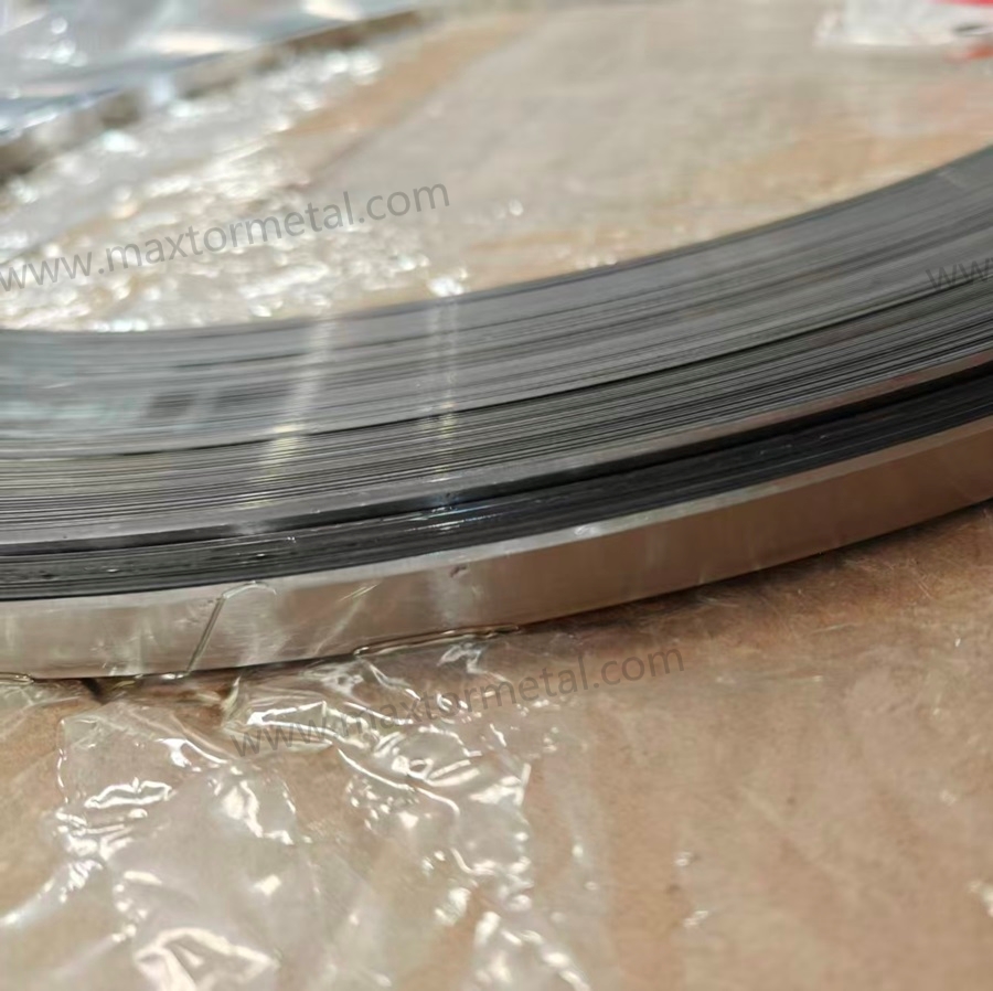
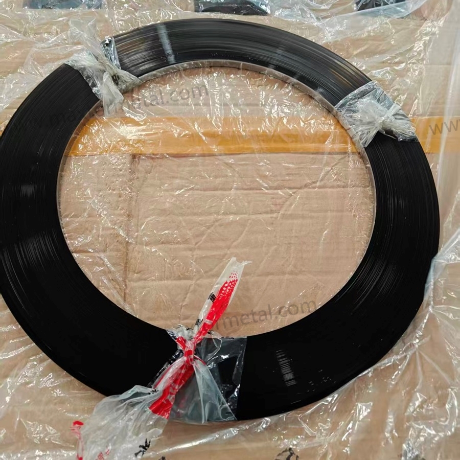
Engineering Note: If your validation plan also covers incoming strip form and ordering language, see Maxtor Metal’s industrial blade strip steel in beveled reels for form-factor specifications — including coil lengths, thickness tolerances, and surface finish grades — aligned with this QA protocol.
이 가이드에 대하여 (및 신뢰할 수 있는 이유)
This guide is written from the perspective of a blade manufacturer operating under a quality-system mindset: defining a controllable process window, tying requirements to auditable records, and using field data to close the loop.
무엇 Maxtor Metal can support in a qualification program (examples of documentation we can provide):
- Incoming inspection records for strip/band (dimensions, visual criteria, sampling plan, disposition) — shareable
- Hardness gage control: calibration certificate and calibration interval statement — shareable
- Heat-treatment batch records: time/temperature charts, quench media notes, sub-zero cycle, temper parameters — shareable
- Heat/lot traceability from incoming strip to finished dicer bands
- In-process and final inspection records
- Material test reports (MTR) / chemistry records with heat/lot identifiers — available under customer NDA
- Hardness sampling map + results — available under customer NDA
- Metallography support for qualification lots and failure analysis; metallography photos/reports (location, magnification, acceptance notes) — available under customer NDA
- Grinding / surface integrity screening records (burn screening method + acceptance criteria) — available under customer NDA
- Surface roughness (Ra) test records including cutoff, direction, sampling locations — available under customer NDA
- Retained austenite (RA) by XRD is typically verified via an approved third-party laboratory when RA quantification is required
If you want to align this guide with your plant’s QA system, use it as a template and adjust acceptance bands to your equipment, product mix, and risk profile.
440C 소재의 기본 개념
Composition and product forms
440C is a high-carbon martensitic stainless steel designed to reach high hardness after hardening and tempering. The key point for dicer bands is that the alloy’s performance comes from a martensitic matrix plus carbides—so chemistry, carbide distribution, and heat treatment all show up as real differences in edge life and chipping behavior.
A practical way to write your incoming material requirement is:
- Specify the grade (440C / UNS S44004 or equivalent)
- Define allowed product forms (strip/band suitable for forming and finishing into dicer bands)
- Bind the grade to documentation: heat/lot traceability + chemical composition record
For a canonical composition reference, ASM International’s Alloy Digest entry for AISI Type 440C is a good starting point.
Properties at HRC 56–58
HRC 56–58 is a common “middle band” for dicer service because it targets a balance:
- High enough hardness for wear resistance and edge retention
- Enough toughness margin to reduce micro-chipping during transient impacts (product inclusions, ice, hard spots, misfeeds)
The catch: the same Rockwell hardness can hide very different microstructures (carbide size/distribution, retained austenite content, temper condition). That’s why hardness is necessary—but not sufficient—as a release criterion.
핵심 요점: Treat HRC 56–58 as an acceptance window that must be paired with microstructure/RA checks and surface integrity checks to be predictive in the field.
Cleanliness options (ESR/VIM)
For Urschel-style dicer bands, conventional air-melt 440C is typically the default from a cost/performance standpoint—provided you control inclusions and variability via incoming QA and process validation.
When would you consider cleaner melting routes?
- ESR (electroslag remelting): when your failure mode is inclusion-driven edge chipping and you need tighter cleanliness.
- VIM and/or VIM+ESR: when you’re chasing the highest consistency and can justify the extra cost (or the application is extremely sensitive to scatter).
A practical approach is to qualify conventional melt first with a strict validation protocol, then “upgrade” only if your field data shows the limiting mechanism is cleanliness rather than heat treat, geometry, or surface damage.
440C 다이서 밴드형 칼날의 적정 열처리 조건(Window) 정의 방법
Austenitize and quench ranges
Most processing windows for martensitic stainless place 440C austenitizing roughly in the ~1850–1950°F range (section size and furnace capability matter), followed by a controlled quench. The bounds matter for opposite reasons: austenitizing below the lower end risks incomplete carbide dissolution and patchy hardness; pushing past the upper end dissolves too much carbon into the matrix, which drives retained austenite up and reduces the martensite fraction you’re trying to achieve.
Two rules that prevent most misprocessing:
- Don’t treat austenitize temperature as “higher is safer.” Excessive temperature/soak can shift RA upward and alter carbide condition.
- Don’t treat quench as “anything fast.” Choose a quench that hits your transformation needs without cracking or distortion.
For a baseline reference on stainless heat treatment ranges and considerations, ASM’s Heat Treatment of Stainless Steels is a useful canonical source.
Sub-zero and tempering for toughness
The common reason dicer bands meet hardness but still chip is microstructure mismatch—often too much RA, poorly stabilized martensite, or high residual stress.
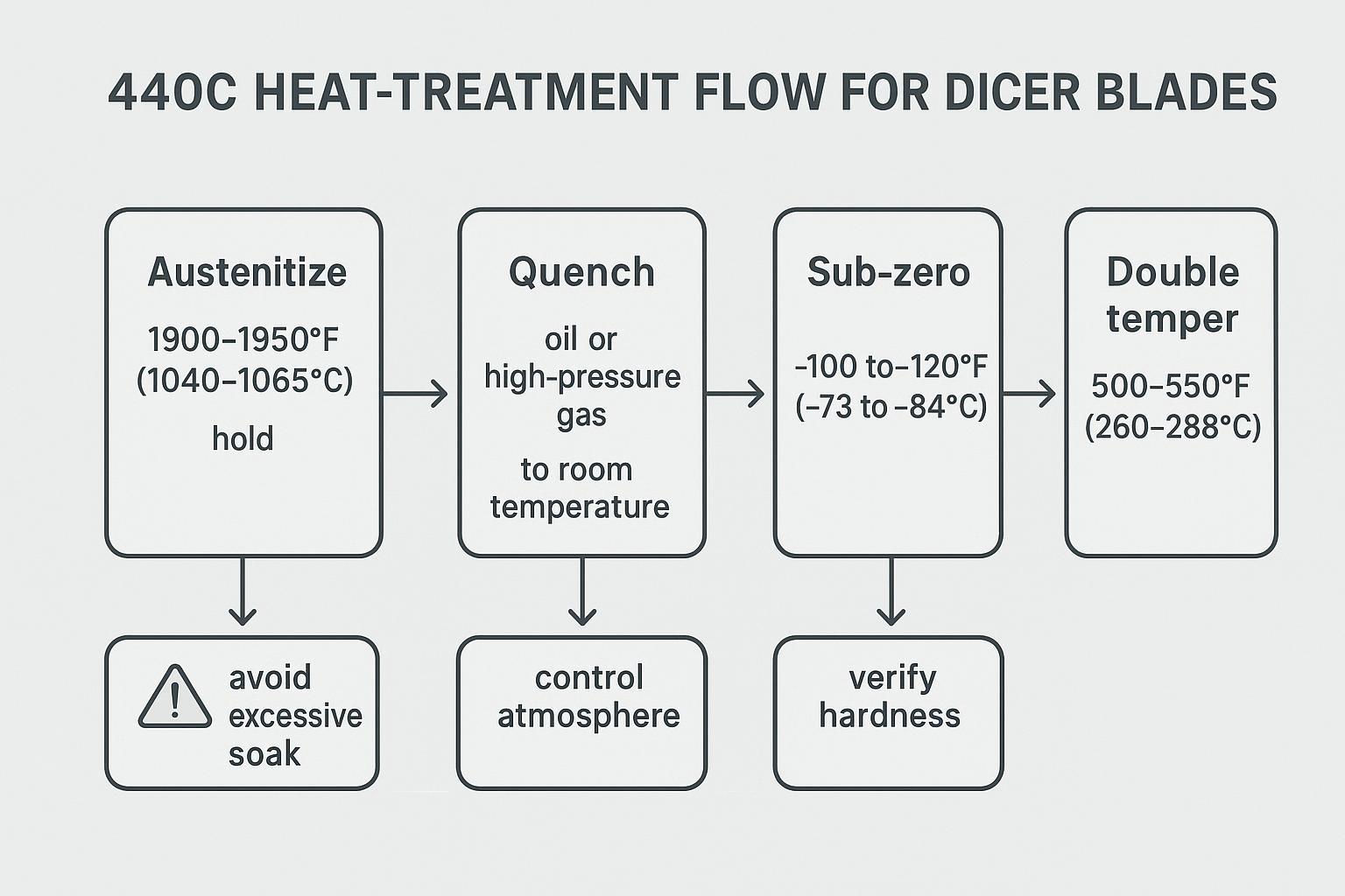
A practical, shop-floor-friendly sequence used by many processors is:
- Austenitize (within your validated band)
- Quench
- Sub-zero (cold treatment) to reduce RA and stabilize
- Double temper to relieve stress and tune hardness/toughness
A defensible way to specify this is not “use this exact recipe,” but:
- Require documented furnace controls and batch records
- Require the supplier to declare their validated ranges for each step
- Verify outcomes with hardness + RA + microstructure + field trial KPIs
Microstructure targets and pitfalls
For dicer bands, the microstructure targets are functional:
- Tempered martensite matrix with appropriate carbide distribution
- RA controlled to a band that matches your chipping-risk tolerance
- No evidence of surface thermal damage from grinding (burn) that creates brittle layers
Common pitfalls that show up as premature chipping or erratic life:
- High retained austenite: may pass hardness but reduces stability and can transform under load.
- Over-austenitizing: can drive RA up and change carbide condition.
- Under-tempering or inadequate temper cycles: leaves high residual stress.
- Grinding burn / rehardening: creates a brittle skin and microcracks at the edge.
HRC 56–58이 필수적이지만 그것만으로는 충분하지 않은 이유: QA 및 검증 프로토콜
Hardness and impact methods (ASTM E18/E23)
Hardness is the fastest screening metric, but only if the method is controlled.
- Use a standards-based Rockwell method such as ASTM E18 and define:
- scale (typically HRC for hardened martensitic stainless)
- number of indents per part/lot
- location plan (avoid edges, avoid thin unsupported zones)
- gage R&R expectations
If chipping resistance is critical, add a toughness proxy with a consistent method such as ASTM E23 (Charpy). For thin band/blade geometries, you may need a subsize specimen plan, but the core benefit is comparing lot-to-lot 그리고 process-to-process rather than chasing an absolute number.
Microstructure and RA checks (third-party XRD + metallography)
Two checks close the “hardness gap”:
- Retained austenite (RA) by XRD: set a release band appropriate to your risk profile and application. If you don’t have in-house XRD, define an approved third-party lab and lock the method so results are comparable lot-to-lot.
- Metallography: verify carbide distribution, martensite condition, and any abnormal structures; correlate with failure analysis.
Practical RA acceptance guidance (how to set a band)
Because Rockwell hardness can be similar across very different microstructures, RA should be treated as a predictive release metric—especially when the dominant failure mode is edge chipping.
For wet-service dicer band applications such as Urschel-style heads, Maxtor Metal’s engineering practice is to use ≤5% RA as a starting control target during qualification, then tighten or relax the band based on field chipping data. This is not a universal number—geometry, product hardness, and sanitation chemistry all shift the optimum—but it gives procurement documents a defensible, auditable starting point rather than an open-ended instruction.
A defensible way to specify RA in procurement documents is:
- Qualification stage: define an RA target based on failure mode and stabilize it with field results.
- If your dominant risk is micro-chipping/brittle edge failures, start with a lower RA target(≤5% is a common field starting point for dicer band service).
- If your dominant risk is distortion/cracking risk in heat treat, avoid overly aggressive RA reduction and use trials to confirm.
- Production surveillance stage: once the process is proven, keep RA as a periodic audit metric to control drift.
Note: the “right” RA number depends on geometry, processing route, and service conditions. If you already have baseline RA data from a known-good band, use that baseline to set your acceptance band rather than adopting a generic number.
What to document (so the data stays auditable)
- specimen prep method and location
- etchant and imaging magnification (metallography)
- RA measurement method parameters (XRD setup) and reporting format
- measurement uncertainty / repeatability statement from the lab (so you can set a realistic acceptance band)
- the acceptance band and the corrective action when out of band
Out-of-band actions (examples)
- RA higher than your band while hardness is in spec → review austenitize/soak control, quench severity, sub-zero step effectiveness, and temper stabilization; re-check for grind burn before release
- RA lower than expected with increased cracking/distortion risk → review quench and cold treatment severity; confirm geometry stability and residual stress condition
A simple way to set acceptance bands (no guesswork)
If you don’t want to debate “generic” RA numbers, set your acceptance bands from a known-good baseline lot, then tighten them as field data accumulates.
| 미터법 | What to collect in the baseline lot | A practical acceptance-band rule | Why it works |
|---|---|---|---|
| 경도(HRC) | n measurements per lot using a fixed location plan | Use your spec window (e.g., 56–58) and add a drift check (e.g., median stays inside the window across lots) | Prevents “meets spec but drifting” situations |
| RA by XRD | n measurements, same specimen location, same lab/method | Start with a percentile band (e.g., keep future lots within the baseline 10–90% range), then tighten if chipping risk is high | Robust when you don’t trust normality assumptions |
| Edge life | n trials per lot (hours or tons) under the same product mix | Track the median and 10–90% range per lot; require non-regression vs baseline before approving changes | Separates true improvement from outliers |
| Chipping rate | chips per inspection interval with the same inspection method | Use a simple rule: if the median worsens vs baseline for two consecutive lots, trigger a root-cause review | Creates an early-warning system |
Tip: when using third-party XRD, require the lab to report repeatability/uncertainty so you don’t set a band tighter than the method can reliably resolve.
Geometry, burn, and surface finish (Ra ≤ 32 µin)
For replacement dicer bands, geometry and surface integrity often dominate “mysterious” field failures. Include explicit checks for:
- flatness / straightness (fit-up stability)
- edge geometry (bevel angle, land, edge radius if specified)
- burr control
- grinding burn and microcracking (nital etch, Barkhausen where appropriate, or microscopy)
For product-contact surfaces, a common hygienic baseline is Ra ≤ 0.8 µm (32 µin). 3-A sanitary design guidance frequently references this threshold; see the 3-A SSI deck Basics of Sanitary Design. EHEDG design guidelines consistently specify product-contact surfaces smoother than Ra = 0.8 µm; see EHEDG Guideline Document 8 for the relevant hygienic equipment design criteria.
Make Ra requirements comparable by specifying measurement details (otherwise different suppliers may report different numbers for the same surface):
- measurement direction (parallel/perpendicular to grind lines)
- evaluation length and cutoff / filter setting used by the profilometer
- number of traces per part and the sampling locations
A practical acceptance package ties finish to function:
- Ra (specify the measurement cutoff and direction)
- visual finish criteria (no pits, laps, embedded debris)
- passivation status (see next section)
Maxtor Metal quality controls and traceability records (technical integration): A QC-oriented supplier should be able to provide a traceable record set for each lot, such as:
- heat/lot number linkage from strip to finished band
- material test report (chemistry) and incoming verification
- heat-treat batch record (time/temperature charts, quench media, sub-zero cycle, temper cycles)
- hardness sampling map and results
- microstructure photo set and RA report (XRD) for qualification lots (and periodic surveillance thereafter)
- surface finish (Ra) records and burn screening criteria
- nonconformance disposition and corrective-action link when a lot is out of band
This isn’t marketing fluff—it’s what lets a plant engineer correlate a chipping spike to a specific heat treat batch, grind wheel condition, or strip heat.
위생 및 규정 준수
Cleaning and passivation (ASTM A380/A967)
In wet food-processing service, “stainless” isn’t a binary state. Surface condition (free iron, embedded grit, smeared metal from machining) can change corrosion behavior and cleanability.
Two widely cited references to anchor your cleaning/passivation language are:
- ASTM A380 for cleaning/descaling/passivation practices
- ASTM A967 for passivation treatment options and related requirements
Write your spec so sanitation steps are verifiable:
- define the cleaning/passivation method class to be used
- require documentation of the process and any verification tests you rely on
Chemical compatibility in washdowns
Dicer environments often see aggressive washdowns, temperature swings, and chloride exposure. Even with 440C, corrosion risk increases when:
- chloride concentration is high
- there are crevices or rough surfaces
- passivation is inconsistent
- residues remain trapped under bands or hardware
This is where surface finish, passivation discipline, and assembly hygiene matter as much as the alloy selection.
Documentation and traceability for audits
If you’re in a regulated or audit-heavy environment, treat blades/bands as controlled components:
- link each lot to a traceability packet
- store heat-treat records and inspection data by lot
- define retention time and retrieval process
The payoff is simple: when a plant sees a sanitation deviation or foreign material risk, you can isolate by lot and respond with evidence.
현장 테스트 및 ROI (투자 회수율)
Why ROI framing matters for blade qualification
For procurement and production managers, the question behind any blade qualification is simple: does the cost and effort of running a validated program pay off? The answer is almost always yes—but only if you measure the right things.
A practical way to frame the ROI case before a trial:
| Cost driver | Typical measurement unit | Where validated 440C at HRC 56–58 reduces cost |
|---|---|---|
| Blade changeover downtime | Minutes/week × labor + line rate | Longer, more consistent edge life reduces unplanned stops |
| Blade consumption rate | Bands per ton processed | Reduced chipping scatter extends usable life per set |
| Cut-size rework/waste | % yield loss on critical cut dimension | Tighter Cpk on HRC and RA → more consistent cut geometry |
| Supplier qualification overhead | Engineer-hours per lot | Standardized documentation package reduces re-qualification burden |
Example framing (hypothetical): A mid-size frozen vegetable processor running two Urschel lines might see blade changeover account for 20–40 minutes of downtime per week per line under an unvalidated supply program. If a validated process window improves edge-life consistency, it can be reasonable to expect a meaningful reduction in that downtime—but the exact number depends on product mix, sanitation cycle frequency, and baseline blade life. That’s why predefining trial KPIs (see below) is the only reliable way to measure your specific ROI.
Key Takeaway: Blade validation is not a cost—it is the mechanism by which you convert a commodity purchase into a controlled consumable with predictable cost-per-ton.
최소 검증 템플릿 (QA 계획서에 복사/붙여넣기용)
Use this as a “minimum viable” qualification pack for replacement dicer bands. It is designed so a plant can audit the lot, reproduce the processing window, and run CAPA when results drift.
Stage 1 — Qualification lots (prove the process window)
Use this stage when you are onboarding a supplier, changing strip source, changing heat-treatment routing, or adjusting finishing.
A) Incoming material (strip/band)
- Supplier, PO, part number / drawing revision
- Grade designation (440C / UNS S44004 or equivalent)
- Heat/lot number and traceability linkage
- MTR / chemistry record (under customer NDA if required)
- Incoming inspection record: dimensions, visual criteria, sampling plan, disposition
B) Process records (heat treat + finishing)
- Heat-treat batch ID + time/temperature chart
- Quench media notes + control checks
- Sub-zero step (temperature, time, sequence)
- Temper cycles (count, temperature range, time)
- Grinding / finishing record (wheel spec, dressing interval, coolant condition, operator/shift)
Maxtor Metal maintains batch-level records for each of these steps as standard practice; qualification customers can request the full documentation package under a mutual NDA.
C) Release tests (qualification lot)
- Hardness (ASTM E18): sampling map, number of indents, results, gage status
- Surface integrity: burn screening method + acceptance criteria
- Surface finish (Ra): instrument settings (cutoff), direction, sampling locations, results
- Metallography: photo set ID, location, magnification, acceptance notes (under customer NDA if required)
- RA by XRD (third-party, if required): lab, method reference, location, result, uncertainty/repeatability statement
D) Field trial log (qualification lots)
- Installation: date/time, line, product type, sanitation cycle notes
- KPI log: edge life, chipping rate, downtime, cut-size Cpk
- Removal reason: planned vs failure, with photo evidence when possible
Stage 2 — Production lots (control drift)
After the process window is proven, keep a lean release plan on every lot and move deeper tests to periodic surveillance.
A) Lot release (every lot)
- Traceability linkage (heat/lot → finished band)
- Hardness check with the same location plan
- Surface integrity screening (burn) and Ra verification per your agreed sampling plan
- Confirm heat-treatment batch record is complete and within declared ranges
B) Periodic surveillance (e.g., on a scheduled cadence or when drift is suspected)
- Metallography photo set review
- RA by third-party XRD (when RA is a controlling risk)
- Expanded dimensional/geometry audits
Out-of-spec & CAPA triggers (simple, audit-friendly rules)
- Any release metric out of band → quarantine the lot and run a documented disposition (use-as-is / rework / scrap)
- If a KPI regresses vs baseline for consecutive lots or shows a consistent drift trend → trigger a root-cause review
- Prioritize checks in this order when failures are ambiguous: burn/surface integrity → RA/microstructure → heat-treat records → strip heat/MTR
Trial design and KPIs in frozen and root crops
A good trial doesn’t just ask “did it last longer?” It asks whether the new bands improve repeatable output without raising risk.
Trial design principles:
- Compare against a baseline band under the same product mix and sanitation cycle.
- Control one variable at a time (material/HT/finish), or you won’t know what caused the outcome.
- Predefine the run duration or throughput target.
KPIs that travel well across frozen and root crops:
- edge life (hours or tons processed)
- downtime (minutes/week attributable to band changeover or rework)
- chipping rate (chips per inspection interval, or % bands failing before target)
- cut-size capability (Cpk on the critical cut-size dimension)
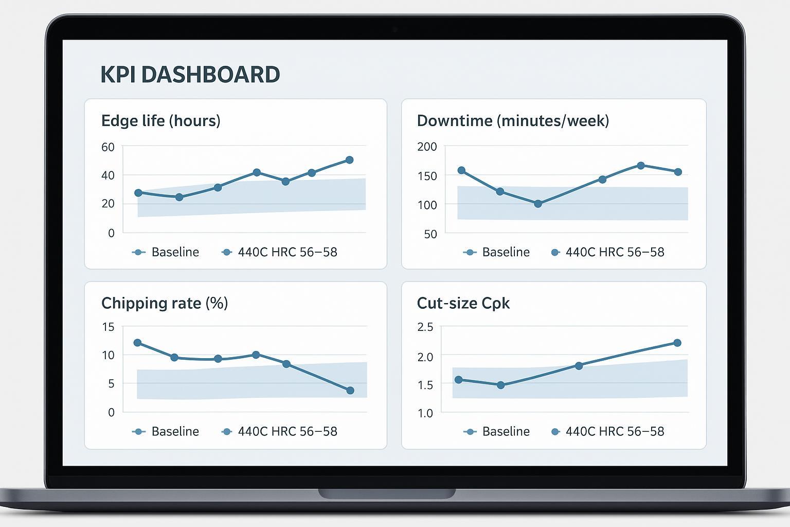
How to present trial results (so decisions are data-backed)
To reduce debate and make trials comparable across lots, define a simple statistical view upfront:
- Lot-to-lot scatter: use box plots for edge life (hours/tons) and chipping counts per inspection interval
- Stability over time: use a basic control chart for chipping rate or downtime minutes/week
- Capability: report cut-size Cpk on the critical dimension with the same sampling method each run
If you only do one thing: report sample size (n), 그 median그리고 10–90% range for edge life per lot. That usually reveals whether you have a true process-window improvement or just a “best-case” outlier.
Make the trial “audit-ready” by defining acceptance bands upfront:
- HRC 56–58 is the hardness band—define the sampling plan.
- Define a chipping threshold (what counts as a fail).
- Define Cpk targets (or the minimum improvement delta) for cut-size.
- Define sanitation outcomes (no abnormal corrosion/pitting after a defined washdown cycle count).
A practical logging checklist:
- lot ID + heat-treat batch ID
- installation date/time, line, product type
- sanitation cycles and chemistry notes
- inspection intervals and findings (chips, burn, corrosion marks)
- reason for removal (planned vs failure)
Root-cause feedback to process window
When a trial misses targets, force a closed-loop diagnosis rather than “try a different supplier” guessing:
- If hardness is in band but chipping is high → prioritize RA/microstructure check + grind burn screening.
- If edge life is low with clean edges → revisit carbide condition (austenitize/temper window) and surface finish.
- If corrosion appears early → revisit passivation and surface finish, then confirm washdown compatibility.
Done well, your field trial becomes a control loop: it tightens the heat-treatment and finishing window until the outcome is predictable.
대체재 및 선정 기준
420 vs 440C trade-offs
420-class martensitic stainless generally offers:
- better toughness margin at a given corrosion resistance level
- lower achievable wear resistance than 440C at comparable processing
If your dominant failure mode is brittle chipping (and not wear), 420 variants can be worth evaluating—but you’ll usually pay for it in edge life unless geometry and process changes compensate.
D2/M2 risks in wet service
High-wear tool steels like D2 and high-speed steels like M2 can deliver excellent wear resistance, but wet service introduces risks:
- corrosion and staining
- sanitation chemical sensitivity
- crevice corrosion at interfaces
If you go this route, you’re often forced into coatings, tighter cleaning constraints, or more aggressive surface protection—each with its own validation burden.
PM stainless options and when to upgrade
Powder-metallurgy (PM) stainless options can improve cleanliness and consistency, and may reduce inclusion-driven chipping scatter. Upgrade triggers typically look like:
- you’ve validated geometry, finishing, and conventional 440C heat treat
- failure analysis still points to cleanliness/inclusion sensitivity
- ROI still works after the material premium
적용 범위 및 한계
This guide is intended for qualification and supplier validation of 440C dicer replacement bands operating in wet, sanitation-driven environments.
- Use it when your goal is repeatability: stable hardness, controlled microstructure/RA (when required), and verified surface integrity.
- Treat all numeric targets as site-specific: geometry, product mix, sanitation chemistry, and equipment condition can shift the “best” window.
- For unusually severe impact loading, highly abrasive inclusions, or extreme corrosion exposure, treat this guide as a baseline and add additional validation (materials upgrade, coating trials, or application-specific testing).
Final acceptance should be based on documented lot records and your plant trial results (and third-party verification where required).
결론
- 440C remains a cost-effective choice when validated to spec
- Use the defined QA and trial protocol to ensure repeatability
The one-sentence version: For Urschel-style dicer band applications in wet food-processing environments, 440C validated to HRC 56–58 with controlled RA (≤5% starting target), documented heat-treat batch records, and surface integrity screening is the most cost-effective path to repeatable edge life—provided the validation protocol treats hardness as a necessary but not sufficient release criterion.
If you want a spec that holds up across suppliers, the key is to bind “440C at HRC 56–58” to documented process controls: heat/lot traceability, heat-treat batch records, hardness + RA verification, and surface integrity checks. That’s the same discipline Maxtor Metal applies internally to keep performance repeatable across lots. Maxtor Metal qualification packages—including MTRs, heat-treat batch records, hardness sampling maps, and third-party XRD reports—are available to customers running formal supplier validation programs.
For reference language around strip supply forms and how to describe them in procurement documents, you can note earlier—then keep your acceptance criteria in the validation protocol above.
자주 묻는 질문(FAQ):
440C 다이서 교체용 칼날의 적정 경도는 얼마여야 합니까?
HRC 56–58은 날끝 유지력(耐摩耗性)과 일정 수준의 인성(toughness) 마진을 동시에 충족하는 전형적인 합격 기준(Acceptance window)입니다. 단순히 경도 수치만으로 출고 승인을 내리지 마십시오. 미세 조직/잔류 오ーステナイト(retained-austenite) 검사 및 표면 무결성(연삭 번) 체크를 반드시 병행해야 합니다.
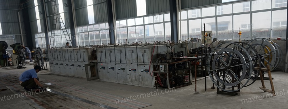
HRC 56–58에 도달하기 위한 440C 권장 열처리 조건은 무엇입니까?
전형적인 제어 프로세스는 1850–1950°F(1010–1065°C) 범위에서 오스테나이트화(austenitize)한 후, 퀜칭(급냉), 잔류 오스테나이트를 줄이기 위한 서브제로(sub-zero) 처리(심냉 처리)를 적용하고, 이어서 더블 템퍼링(재가열/뜨임 2회)을 수행하는 것입니다. 공칭 레시피에 의존하기보다 문서화된 노(furnace) 제어 기록을 사용하고 경도 및 잔류 오스테나이트(RA) 데이터로 결과를 검증하십시오.
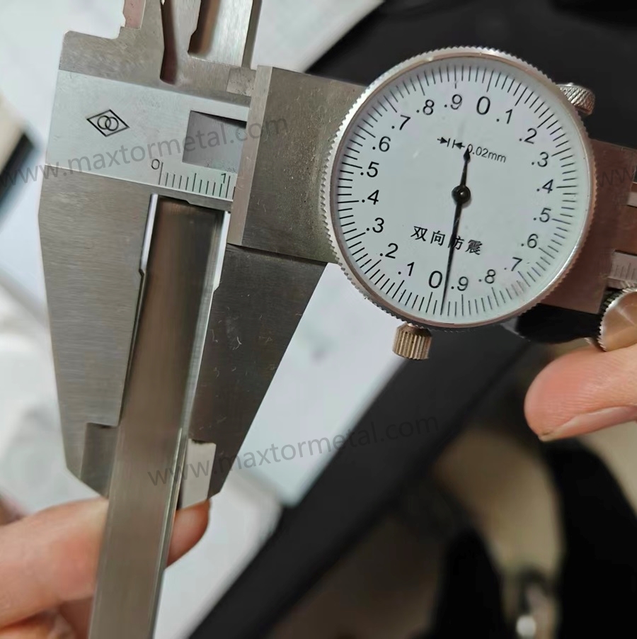
경화된 440C 칼날의 경도를 올바르게 측정하는 방법은 무엇입니까?
ASTM E18과 같은 표준 기반의 로크웰(Rockwell) 경도 측정법을 사용하고, 측정 위치 계획을 정의하며, 로트(Lot)당 샘플링 빈도를 설정하십시오. 잘못된 측정값이 나오는 것을 방지하기 위해 측정 장비 세팅이 박판(thin sections) 측정에 적합한지 확인해야 합니다.
440C에서 잔류 오스테나이트를 어떻게 측정합니까?
엑스선 회절 분석(XRD)이 일반적인 정량적 측정 방법이며, 금상학(metallography) 분석을 병행하여 미세 조직 상태를 검증하는 것이 좋습니다. 중요한 부분은 합격 기준 범위를 설정하고 측정 조건 파라미터를 기록하여 로트(Lot) 간 결과 비교가 가능하도록 하는 것입니다. 어쉘(Urschel) 스타일 다이서 밴드 칼날의 경우, 초기 관리 목표치인 '잔류 오스테나이트(RA) 5% 이하'가 업계에서 통용되는 대표적인 기준점입니다.
식품 접촉용 스테인리스 칼날에 허용되는 표면 조도(Surface finish)는 얼마입니까?
제품 접촉 표면의 일반적으로 통용되는 위생 기준선은 Ra ≤ 0.8 µm(32 µin)이며, 이는 3-A 위생 디자인 가이드라인에 명시되어 있고 EHEDG 문서에도 반영되어 있습니다. 공급업체(suppliers)들이 동일한 방식으로 데이터를 제출할 수 있도록 귀사의 측정 방법과 측정 방향을 명확히 정의하십시오.
스테인리스 다이서 밴드 칼날의 부동태화(Passivation) 처리에 어떤 표준을 참조해야 합니까?
세척 및 부동태화 실무에는 ASTM A380을 사용하고, 화학적 부동태화 처리 옵션 및 요구사항에는 ASTM A967을 사용하십시오. 그런 다음 문서화 및 검증(Verification) 요건을 명시해야 합니다.
경도 수치가 스펙 이내인데도 440C 다이서 칼날에 치핑(날끝 깨짐)이 발생하는 이유는 무엇입니까?
경도만으로는 잔류 오스테나이트 수치, 탄화물 분배 상태, 잔류 응력, 연삭 번(grinding burn) 등을 파악할 수 없기 때문입니다. 날끝 깨짐 현상은 대개 잔류 오스테나이트(RA)가 지나치게 높거나, 템퍼링(뜨임) 안정화가 부족할 때, 혹은 표면 열화 손상이 원인이 되어 발생합니다.
대체용 다이서 밴드 칼날의 품질을 검증하기 위한 공장 실장 테스트(Plant trial)는 어떻게 설계해야 합니까?
통제된 베이스라인 비교 방식을 사용하고, KPI(날끝 수명, 다운타임, 치핑률, 컷 사이즈 Cpk)를 사전에 정의하며, 시작 전에 합격 기준 범위를 설정하십시오. 불량이 발생했을 때 공정 조건(Process-window)상의 원인을 추적할 수 있도록 로트 ID, 세척 소독 주기, 검사 결과를 기록해야 합니다. Maxtor Metal은 이 프로세스를 지원하기 위해 테스트 문서 템플릿과 로트별 추적성(Traceability) 기록을 제공할 수 있습니다.
작가
제시 쉬 — Senior Quality Engineer, QA (Quality Assurance), Maxtor Metal
- 경험: 15 years in quality engineering, with hands-on 고장 분석 experience to distinguish whether edge chipping or rapid wear is driven by heat-treatment process variation versus material segregation.
- 자격증: ASQ–CQE, ISO 9001 Lead Auditor, ASNT Level II