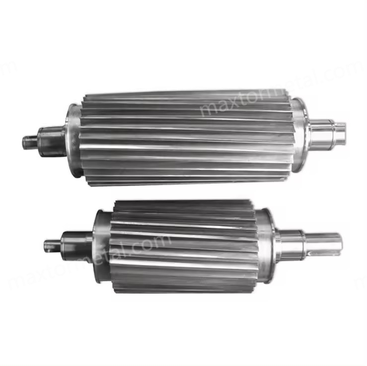
Inspecting a rotary cutter and bed knife with micrometer and optical scope to verify geometry before reinstallation.
Pellet quality, uptime, and total cost per ton all hinge on one deceptively simple thing: edge accuracy. When the cutting edges on the rotary cutter and bed knife drift from target geometry, pellets show tails and fines, vibration climbs, and unscheduled interventions creep into the calendar.
A professional precision grinding service restores critical elements—edge geometry, dimensional tolerances, and surface finish—to specification. That means edges that are sharp yet robust, faces that are flat and parallel, and surfaces that glide rather than drag.
The outcome is practical and measurable: fewer fines and tails, longer between-changeover run times, and predictable set-and-hold adjustment behavior that stabilizes both quality KPIs and your cost/ton. In other words, this is where precision grinding for rotary cutters and bed knives in a strand pelletizer pays for itself.
Key takeaways
- Start with scenario-appropriate targets: edge radius 8–12 µm (within 5–20 µm range), flatness/parallelism ≤10–25 µm, Ra 0.2–0.8 µm, rotor–bed gap 0.20–0.30 mm for PP/PE, TIR ≤0.03–0.08 mm, balance G2.5–G6.3.
- Treat fines (%) and tail length (mm) as SPC feedback to tune micro‑hone radius and gap; verify at thermal steady state.
- Use fine‑grit superabrasives, light finishing passes, and disciplined wheel dressing to hit Ra without burning.
- Balance to ISO 21940 grade selected and confirm TIR on the assembled rotor—vibration drives wear and cost.
- Expect TCO wins from fewer changeovers and lower scrap; validate with your own KPI log (fines %, uptime hours, unplanned stops/month).
Why precision grinding matters
Link to pellet quality
Pellets don’t fail inspection because of magic—they fail when the cut becomes a tear. A controlled micro‑hone (edge radius) with the correct attack angle produces a clean, scissor‑like shear through the strand. Excess radius or a rough finish smears polymer, raising tails and fines. OEM literature stresses adjustable, rigid mechanisms for clean cuts; for example, MAAG’s PRIMO series describes precision adjustment and stable cutting action suited to PP/PE even if it doesn’t publish numeric gaps. See the adjustment emphasis in the MAAG PRIMO E brochure (MAAG Group) and the setup basics in Bay Plastics Machinery’s training notes.
Uptime and fewer interventions
Flat, parallel faces and tight TIR eliminate hot spots and chatter that accelerate wear. When the knife pair holds geometry and the rotor is balanced to an appropriate ISO 21940 grade, adjustments hold longer and operators spend less time nursing the gap. The result is fewer micro‑stoppages and longer, calmer runs.
Cost/ton and waste reduction
Here’s the deal: modest improvements compound. A 15% run‑length increase plus a 20% fines reduction can trim dollars per ton by cutting changeovers, downtime, and scrap reprocessing.
Worked TCO example (illustrative, not a guarantee)
- Baseline (clean PP/PE): changeover every 40 h; fines 1.2%; throughput 1,000 kg/h; line value $0.10/kg; knife pair $400; resharpen $120; changeover downtime 1.0 h at $500/h.
- With precision grinding: run length +15% (46 h); fines −20% (0.96%).
- Per 46‑h cycle: material processed 46,000 kg vs. 40,000 kg baseline; scrap reduction (1.2% − 0.96%) × 46,000 = 110.4 kg → $11.04 saved/cycle.
- Fewer changeovers per 1,000 operating hours: baseline 25; improved ≈ 21.7 → 3.3 fewer changeovers → downtime savings ≈ 3.3 × $500 = $1,650 per 1,000 h.
- Knife costs amortized over longer interval reduce cost/h by ≈15%. Combined, this often equals several dollars/ton saved—confirm with your site rates and SPC.
Geometry and tolerances that restore cut quality
Edge angles and radius targets
For standard, unfilled PP/PE (scenario 2A), start with an edge micro‑hone radius of 8–12 µm within a recommended range of 5–20 µm. Keep the attack angle in the 5–20° window depending on holder and die geometry. Too sharp (<5 µm) risks chip welding and fuzz; too blunt (>20 µm) raises forces and bends strands. Tune by monitoring fines % and tail length after thermal steady state.
Flatness, parallelism, and surface finish
Verify flatness and parallelism per ISO 1101 with either a CMM or a certified granite plate and dial indicator fixture. Apply capable gaging (10–25% of tolerance). Target surface finish Ra 0.2–0.8 µm, measured per ISO 4287/4288 with an appropriate cutoff length and sampling; Mitutoyo’s guidance explains Ra measurement practice and decision rules well—see Mitutoyo’s surface roughness guide. For a neutral ISO 4287 overview, Digital Surf’s primer is also useful: ISO 4287 parameters explained (Digital Surf).
Scope & applicability (read first): The numeric targets below are intended as an engineering starting point for standard, unfilled PP/PE (scenario 2A). If you run mineral-filled compounds (e.g., CaCO₃/talc), glass-fiber reinforced resins, highly abrasive recyclate, or higher-temperature polymers, re-qualify the edge radius, gap, material/coating, and balance grade using your OEM guidance plus on-line SPC feedback.
Measurement capability note: As a rule of thumb, keep measurement uncertainty and gage resolution within ~10–25% of the tolerance band (and confirm with decision rules such as TAR/TUR when you use them). For critical characteristics (Ra, flatness/parallelism, TIR), consider a basic gage R&R target ≤10–20% of total variation before you lock in acceptance criteria.
Below is a compact reference for scenario 2A (unfilled PP/PE):
| Metric | Recommended range | Notes |
|---|---|---|
| Edge radius (micro‑hone) | 5–20 µm (start 8–12 µm) | Starting point for PP/PE; tune via fines/tails SPC at thermal steady state |
| Edge/attack angle | 5–20° | Holder/die dependent |
| Flatness (knife face) | ≤10–25 µm | CMM or plate + indicator; keep gage capability within ~10–25% of tolerance |
| Parallelism (mating faces) | ≤10–25 µm | Verify against datum |
| Surface finish (Ra) | 0.2–0.8 µm | ISO 4287/4288; document cutoff, sampling length, and decision rule |
| Rotor–bed gap | 0.10–0.50 mm (start 0.20–0.30) | Starting point; confirm hot and even across width; verify against OEM guidance |
| TIR (rotor/holder) | ≤0.03–0.08 mm | Investigate if ≥0.05 mm; check hubs/bearings/collets |
| Dynamic balance | G2.5–G6.3 (ISO 21940) | Select for your RPM; tighten for vibration‑sensitive lines |
Gap control, runout, and balance
Set the rotor–bed gap with feelers or an indicator under light preload, then confirm at operating temperature. For PP/PE, a 0.20–0.30 mm engineering starting gap often delivers clean shearing—but treat it as a setpoint to be confirmed against your OEM setup guidance, verified at thermal steady state, and tuned via fines/tails SPC. Adjust for strand diameter and stability.
Check TIR on rotor OD and shaft; if readings creep above ~0.05 mm, inspect hubs, bearings, or collets. If you need a neutral reference for what “runout tolerance” can look like in general machining practice (not pelletizer-specific), see a diameter-based table such as Runout tolerances reference (Welkon).
Balance the assembly to ISO 21940 grade appropriate for your speed—lower vibration preserves edge life and surface finish. For balancing concepts and grade definitions, see the ISO 21940 overview and calculators in ISO 21940-1 (2019) explanatory materials.
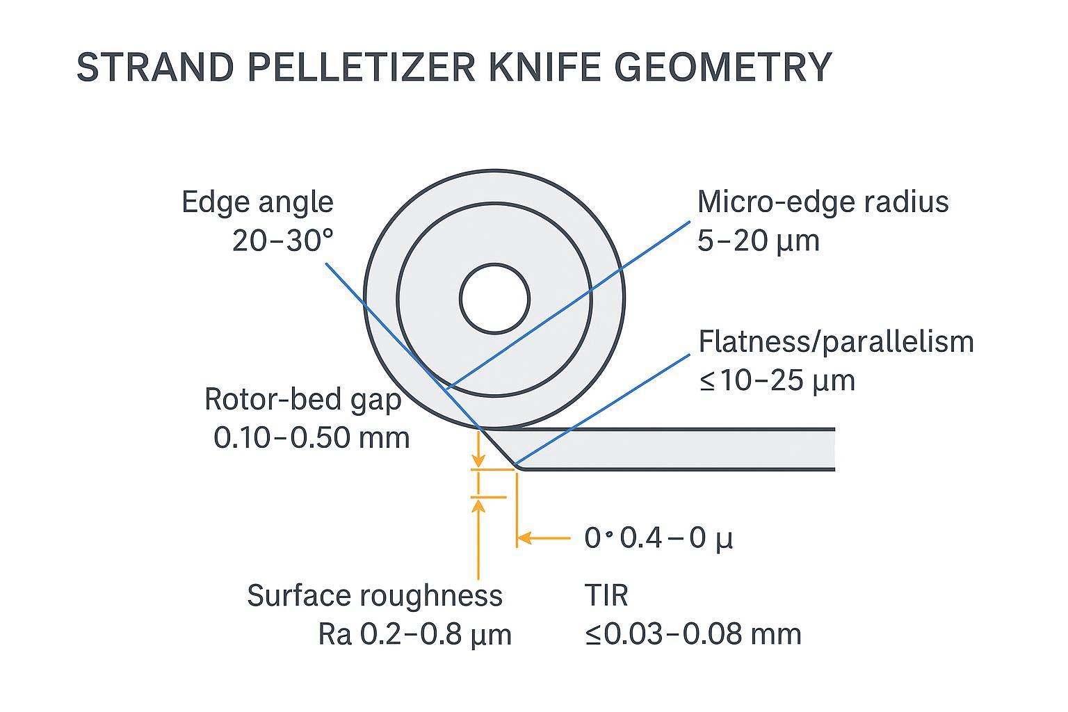
Critical geometry targets for strand pelletizer knives: edge radius, angles, flatness/parallelism, rotor–bed gap, and TIR.
Materials, hardness, and coatings for abrasive runs
Tool steels vs. PM grades
For clean PP/PE, conventional cold‑work tool steels are effective when heat treated correctly. D2 (Böhler K110; 1.2379) at 58–62 HRC offers strong wear resistance; follow the hardening/tempering chart and consider triple temper. See the official Böhler K110 datasheet for heat‑treat windows. A2 is another practical option where a touch more toughness is desired, commonly in the ~58–60 HRC band.
Carbide options and when to use them
For abrasive fillers or mineral‑loaded recipes, tungsten carbide or TiC‑tipped knives can extend life several times over tool steel, reducing changeovers. Suppliers of pelletizer knives often note multi‑fold life improvements in abrasive duty; validate with your resin and line. See application guidance like USG’s TiC bimetal pelletizer knife brief.
Hardness bands, cryo, and coatings
Select hardness first by duty: D2 around 58–62 HRC is typical; confirm hardness per ASTM E18. Consider cryogenic treatment to stabilize retained austenite and improve wear—see MAXTOR METAL’s neutral explainer on cryogenic treatment benefits and their Rockwell hardness guide for measurement fundamentals. Coatings such as TiN/TiCN/DLC can lower adhesion and friction; match chemistry to PP/PE operating temperatures and any slip agents.
For finishing hard steels and carbide without thermal damage, fine‑grit cBN/diamond wheels, disciplined dressing, and flood synthetic coolant are your friends. See Norton Winter’s tool grinding overview for superabrasive selection principles.
Resharpening workflow and best practices
Grinding media, coolant, and passes
Use cBN (vitrified or resin) for D2/A2 and diamond for carbide. Rough in controlled steps and finish with multiple light passes to reach Ra ≤0.8 µm while protecting straightness and flatness. Dress frequently to keep the wheel sharp and prevent burn; maintain coolant concentration and flow to stabilize temperature and surface integrity.
Edge honing, cleaning, and inspection
After finish grinding, apply a controlled micro‑hone to 8–12 µm for PP/PE using a brush or abrasive film. Ultrasonically clean to remove residues; dry thoroughly and apply corrosion inhibitor if storage is expected. Inspect flatness/parallelism (µm), Ra per ISO 4287/4288, and confirm edge radius with appropriate optical methods or calibrated edge‑radius gages.
Balancing, intervals, and stock removal
Log stock removal to keep geometry within tolerance over the tool’s life. Schedule resharpening by SPC signals (fines %, tail length, power draw). Balance the rotor/knife assembly to the chosen ISO 21940 grade (often G6.3 for general service; G2.5 for vibration‑sensitive lines). The practical relationship is:
- e_per (g·mm/kg) = 9549 × G / n, where n is rpm. Total permissible residual unbalance U_per = e_per × mass (kg). Split across planes per geometry. A small rotor at 3,000 rpm and 5 kg at G6.3 yields ≈100 g·mm total permissible unbalance.
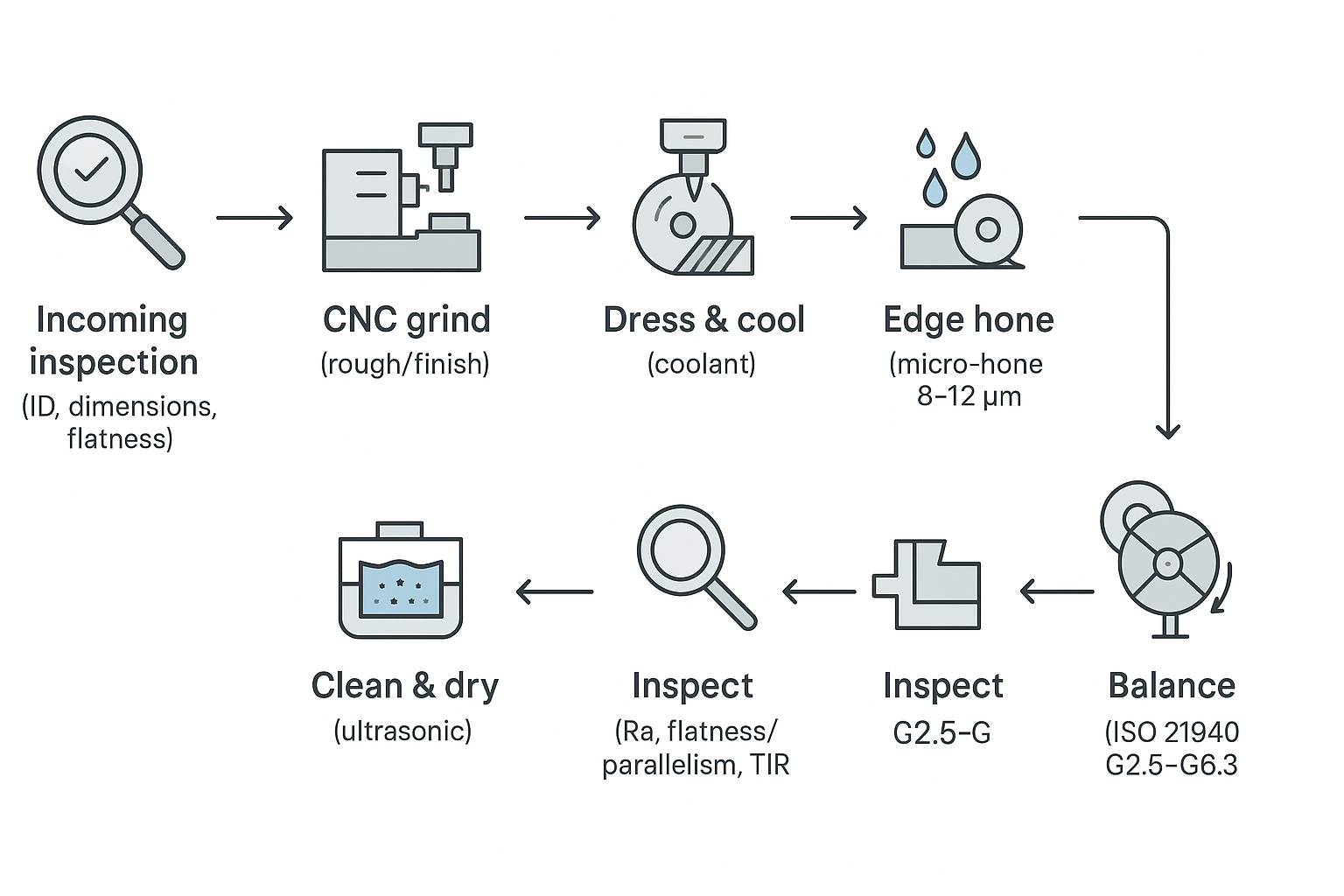
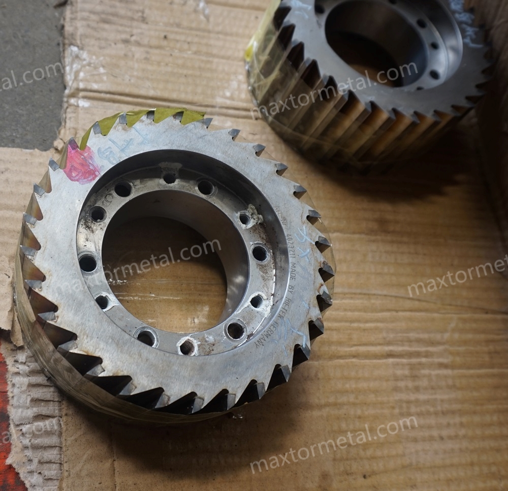
Resharpening workflow from incoming inspection through CNC grind, hone, clean, metrology, and balancing.
QA, documentation, and compatibility checks
Measurement reports and traceability
Minimum report fields should include: part ID and revision, datum scheme, flatness/parallelism (µm), Ra per ISO 4287/4288 with cutoff length, edge radius target/method, hardness (HRC per ASTM E18), TIR points and values, balance grade achieved (ISO 21940), instrument IDs and calibration due dates, inspector name, environment, and date. Keep gage capability within 10–25% of the tolerance band. For Ra measurement practice and decision rules, see Mitutoyo’s surface roughness guide.
Copy/paste QA report template (Markdown):
- Part identification
- Part name / ID:
- Drawing revision:
- Quantity in lot:
- Heat/lot number (material traceability):
- Incoming condition (as-received notes):
- Datums & setup
- Datum scheme (A/B/C):
- Fixturing method:
- Ambient temp / metrology room condition:
- Geometry & finish (record method + points)
- Edge radius target (µm) and method (optical / replica / gage):
- Attack/edge angle (°) and measurement method:
- Flatness (µm): instrument + points (e.g., 3–5 points across face)
- Parallelism (µm): instrument + points
- Surface finish Ra (µm): ISO 4287/4288; cutoff & sampling length; locations (e.g., 2–3 traces/face)
- Assembly checks
- Rotor–bed gap setpoint (mm):
- Gap verification points across width (mm):
- TIR locations (shaft / OD) and values (mm):
- Balance grade achieved (ISO 21940): G____ ; speed (rpm): ____
- Material & hardness
- Material cert received? (Y/N)
- Heat treatment record received? (Y/N)
- Hardness (HRC, ASTM E18): average ____ ; min/max ____ ; locations ____
- Instruments & quality controls
- Instrument IDs used (profilometer, indicator, CMM, hardness tester):
- Calibration due dates:
- Decision rule (if used): TAR/TUR / other:
- Gage R&R (if available): ____%
- Disposition
- Conformance decision (Pass/Fail):
- NCR / deviation notes:
- Inspector / date / sign-off:
Fit-up, holders, and target gaps
Dry‑fit each knife to its holder: verify thickness, hole pattern, chamfers, and seating are correct. Clean datums, then set and verify the rotor–bed gap evenly across the width using feelers or an indicator under consistent preload. Record the setpoint (e.g., 0.25 mm) and verification locations so the next changeover reproduces the result.
Logistics, lead times, and risk control
MAXTOR METAL can provide technical documentation and logistics that slot neatly into plant QA: material certificates, hardness and tolerance/inspection reports (including flatness/parallelism, Ra, TIR, and balance grade), and first‑article records. Their team also supports one‑stop import—transport plus customs handling with status updates—so plants typically receive goods by paying VAT and proceeding with installation. For process transparency, see MAXTOR METAL’s heat‑treatment process guide, cryogenic treatment benefits, and Rockwell hardness guide. Tone aside, the goal is simple: reduce administrative risk while keeping technical traceability auditable.
Example SPC before/after log (template)
Use this as a simple, auditable way to connect grinding/inspection targets to pellet outcomes. Populate it with your own line data (this is a template, not a performance promise).
- Line / resin: (e.g., PP/PE unfilled), strand diameter: ___ mm, throughput: ___ kg/h
- Measurement window: after thermal steady state (Y/N), sample size per check: ___
| KPI | Before (baseline) | After (post-grind) | How measured | Notes |
|---|---|---|---|---|
| Fines (%) | Sieve method / spec: | |||
| Tail length (mm) | Sampling rule: | |||
| Changeover interval (h) | Log source: | |||
| Unplanned stops (count/month) | Definition: | |||
| Vibration (mm/s) or TIR (mm) | Instrument / location: | |||
| Scrap/rework cost ($/ton) | Finance basis: |
Record the matching technical settings beside the KPI log:
- Edge radius target/result (µm): ___ / ___
- Ra target/result (µm): ___ / ___
- Flatness/parallelism target/result (µm): ___ / ___
- Rotor–bed gap setpoint (mm) and hot verification results: ___ ; points: ___
- Balance grade and speed: G___ @ ___ rpm
Conclusion
Precision in geometry, tight tolerances, and disciplined process control are what make a precision grinding service deliver results you can measure in pellets, hours, and dollars.
Next steps: define your targets (edge radius, gap, Ra, TIR, balance grade), schedule resharpening on an SPC cadence, and track fines %, tails, uptime hours, and unplanned stops. Want a neutral certificate pack for a pilot lot? You can request hardness and tolerance reports along with standard import support.
Tommy Tang — Senior Sales Engineer, Nanjing METAL Industrial
- Experience: 12 years in industrial blade applications and technical sales support
- Certifications: CSE, CME, Six Sigma Green Belt, PMP
References cited in text
- Clean‑cut adjustment emphasis and PP/PE suitability: MAAG PRIMO E brochure (MAAG Group); Bay Plastics Machinery training
- Ra measurement and decision rules: Mitutoyo surface roughness guide; Digital Surf ISO 4287 overview
- Balancing grade definitions: ISO 21940-1 explanatory material
- D2 heat‑treat window and hardness: Böhler K110 datasheet
- Superabrasive finishing overview: Norton Winter tool grinding overview