When pelletizing gets tough—abrasive fillers, intermittent impacts, wet chambers, and heat spikes—the wrong pelletizer blade turns your line into a downtime machine. In this context, CPM refers to Crucible Particle Metallurgy, a powder‑metallurgy route that produces fine, uniformly distributed carbides for excellent wear resistance and reliable toughness. Note: CPM is also the well‑known California Pellet Mill brand; in this article, CPM means the steel‑making process and the tool steels derived from it.
Key takeaways
- CPM pelletizer blades pair high wear resistance with usable toughness—ideal for abrasive, high‑load service.
- For dominant abrasive wear, CPM 10V around HRC 60–64 maximizes life; for impact/chipping risk, CPM M4 around HRC 58–62 balances toughness and edge retention.
- The five common failure modes—abrasive wear, impact/chipping, adhesion/galling, corrosion‑wear coupling, and thermal softening—each point to a specific material, hardness, and process‑control response.
- QA your blades with Rockwell hardness mapping (ASTM E18), a wear‑ranking method (ASTM G65), and microstructure checks to prevent surprises on the line.
- Geometry, finish, and alignment matter: micro‑bevels, polished lands, and correct rotor‑stator gaps often add more life than hardness alone.
Failure Modes in High‑Load Pelletizing and What They Tell You
Your best material choice falls out of the failure signature. What are you actually seeing on the edge after a run—uniform recession, chips, smear, pits, or a softened zone?
Abrasive wear — CPM 10V window (HRC 60–64)
Signature: uniform edge recession, polished wear land, gradually increasing fines and energy draw.
What to do: Prioritize high vanadium‑carbide volume in a fine PM matrix. CPM 10V excels here; run it at roughly HRC 60–64 to resist mineral‑filler abrasion. If wear still dominates, evaluate solid carbide bed knives or carbide‑tipped solutions for the extreme end of the spectrum, a path OEMs offer as “wear packages” for glass‑filled runs, as shown in MAAG/Gala strand pelletizer sheets (solid‑carbide bed knives and optional carbide rotors are documented in their product literature).
Why it works: Fine, uniformly dispersed vanadium carbides resist grooving and three‑body abrasion far better than coarse, segregated carbides of conventional ingot steels. Typical working hardness guidance for CPM 10V in cutting applications aligns with the low‑60s HRC window cited in vendor datasheets and proxies such as Zapp’s PM tool‑steel pages.
Impact/chipping — CPM M4 window (HRC 58–62)
Signature: micro‑to‑macro chips, tip breakout, sudden loss of clean cut quality.
What to do: Step toward a tougher PM high‑speed steel. CPM M4 at about HRC 58–62 provides higher transverse toughness and better resistance to crack initiation/propagation. Also thicken the backing section, add a protective micro‑bevel (secondary angle), and maintain perfect alignment to minimize point loads.
Why it works: Compared with high‑vanadium wear steels, PM HSS grades like M4 carry a tougher matrix while still holding a keen edge. Distributors’ datasheets consistently show higher usable toughness for M4 in exchange for somewhat lower abrasive wear resistance than 10V.
Adhesion/galling — finish, coatings, and clearance
Signature: polymer smearing, raised burrs, sticky buildup that drives heat and runout.
What to do: Reduce surface energy and friction at the edge. Superfinish cutting lands (target Ra ≈ 0.2–0.4 µm), keep the edge sharp, and evaluate hard, low‑friction PVD coatings such as TiN, TiCN, or DLC case‑by‑case. Confirm rotor‑stator clearance and die‑face flatness. Some OEMs list Stellite‑tipped rotors and “scissor‑like” cutting geometries for tough, sticky polymers—signals that edge chemistry and geometry matter as much as bulk hardness.
Corrosion‑wear coupling — when PM stainless makes sense
Signature: pitting plus simultaneous abrasive loss (typical in underwater or chemically active systems).
What to do: Move to a martensitic stainless PM option or apply a protective coating if chemistry is the primary driver. Accept that you may sacrifice some abrasive life compared with CPM 10V. Underwater pelletizing systems with tempered water reduce thermal spikes but introduce continuous aqueous exposure; ensure water chemistry control and timely die‑plate refurbishment to prevent galvanic/pitting accelerants.
Thermal softening — temper stability and process cooling
Signature: rapid blunting after high‑heat runs, localized edge softening, slight distortion.
What to do: For dry‑face or heat‑soak conditions, select steels with temper resistance into the 500–600 °C short‑term range and tighten process controls (cooling, gap, purge routines). Underwater systems inherently limit edge temperature; even so, monitor chamber conditions and avoid oven cleaning cycles that overshoot safe ranges.
Choosing Materials: CPM 10V vs CPM M4 vs D2
Your shortlist comes down to how much abrasion you face and how often the blade sees impacts or contamination. Think of CPM 10V as the abrasion specialist and CPM M4 as the toughness specialist; D2 is the budget baseline, and PM stainless or carbide cover special environments.
| Material | Typical working hardness (HRC) | Primary strength | Main risk/tradeoff | Best use case |
|---|---|---|---|---|
| CPM 10V (PM high‑vanadium) | 60–64 | Outstanding abrasive wear | Lower toughness vs PM HSS; chipping risk if misapplied | High‑filler/mineral‑loaded polymers where abrasion dominates |
| CPM M4 (PM high‑speed steel) | 58–62 | Higher toughness with good edge holding | Less wear life than 10V in pure abrasion | Intermittent overloads, contamination, or chipping risk |
| D2 / K110 (conventional cold‑work) | 58–61 | Cost‑performance baseline | Coarser carbides, lower isotropy; earlier onset of chipping | Moderate abrasion, budget‑constrained runs |
| PM martensitic stainless (e.g., 20CV‑type) | 56–60 | Corrosion resistance | Lower carbide volume vs 10V; reduced wear life | Wet/chemical exposure (underwater systems) |
| Solid carbide / carbide‑tipped | N/A (cemented carbide) | Extreme wear resistance | Brittle; chipping under impact; costly | Severe abrasion, stable alignment, low impact |
According to Zapp’s PM tool‑steel data, CPM 10V typically runs in the low‑60s HRC for cutting wear tools, while CPM M4 can operate from the high‑50s into the low‑60s depending on section and duty. Uddeholm’s D2/K110 references place it in the high‑50s/low‑60s HRC but with coarser carbides and lower toughness than PM options. OEM pelletizer documentation corroborates the shift to carbide components for the most abrasive, glass‑filled materials.
Heat‑Treat and Edge Geometry That Extend Blade Life
- Tempering and stability: Use heat‑treat cycles that achieve the target HRC while retaining temper stability. For CPM 10V, aim for the tempering plateau that keeps hardness in the low‑60s HRC without over‑tempering. For CPM M4, select a temper that preserves toughness for your section thickness.
- Edge geometry: Add a micro‑bevel (e.g., 20–30 µm land) to protect the primary angle in abrasive service; sharpen more aggressively only if chipping is controlled. Polish the land to cut adhesion and reduce micro‑notches that launch cracks.
- Alignment and clearance: Keep rotor‑stator gap tight and uniform; misalignment converts steady wear into chipping. Inspect die‑face flatness and ensure clamping doesn’t distort the blade.
- Surface finish targets: Superfinish cutting lands to Ra ≈ 0.2–0.4 µm for sticky polymers; a crisp, polished interface lowers friction and heat.
QA, Testing, and Acceptance Criteria You Can Put in a PO
Bring your supplier into your quality loop instead of hoping for the best. Here’s a compact, auditable kit:
- Rockwell hardness mapping (ASTM E18): Specify HRC at the edge and body, machine verification, and an acceptance band (e.g., ±1 HRC at the edge). Document three locations minimum across the length.
- Wear ranking (ASTM G65): Use dry‑sand rubber‑wheel testing on witness coupons from the same heat‑treat lot to compare batches over time. It won’t replicate pelletizing, but it’s a stable index for abrasion.
- Microstructure snapshot: Request one optical micrograph showing carbide distribution/size. You’re looking for fine, uniform VC clusters in CPM 10V and a clean matrix in M4.
- Trial metrics: Define hours to first regrind or tons processed to the same tolerance window, with failure signature notes (abrasion, chipping, adhesion, etc.). Track changeover minutes and scrap to calculate cost per good ton.
For background and exact method scopes, see ASTM’s overviews of the Rockwell hardness method and the G65 wear test; the standards explain how to control machines, indenters, abrasives, and acceptance tolerances.
Practical Example — Spec’ing a CPM 10V Blade for Abrasive Filler Runs
Disclosure: Nanjing METAL is our product.
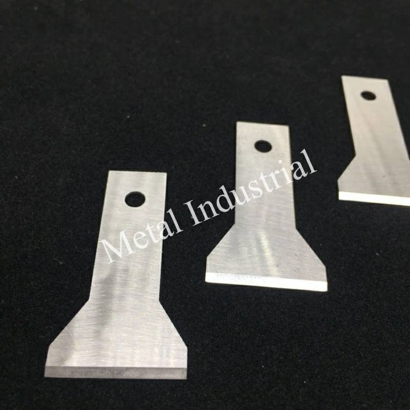
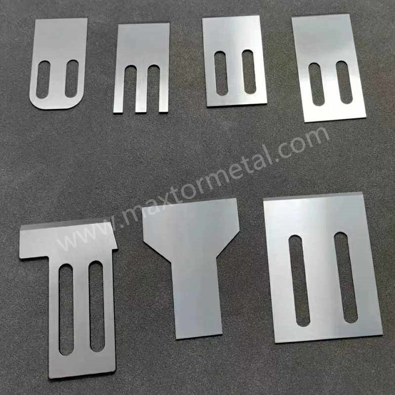
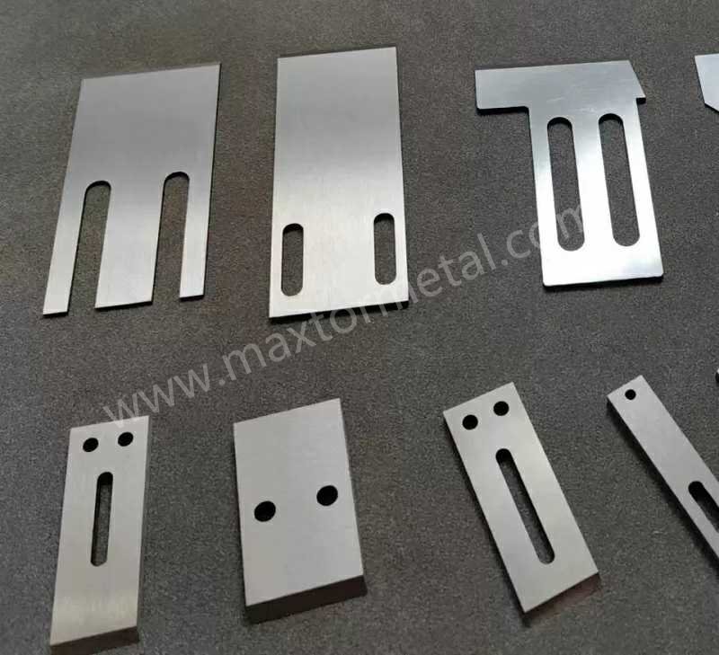
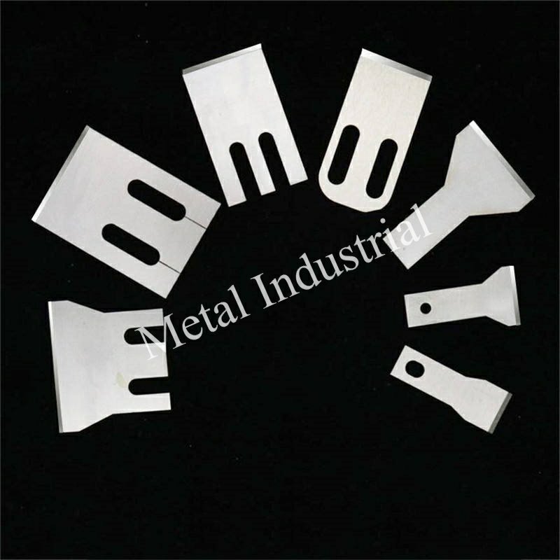
A procurement team needs blades for a glass‑filled PP line that chews through D2. The failure log shows uniform edge recession with no chipping—classic abrasive wear. Spec the material as CPM 10V, target HRC 62 (within the 60–64 window), with a 20–30 µm micro‑bevel and polished land (Ra ≤0.4 µm). Tighten rotor‑stator alignment and map Rockwell hardness at three edge points. In a recent internal trial, a similar spec increased hours to first regrind versus a D2 baseline under comparable load. If your line faces the same pattern, a neutral, custom supplier can manufacture to drawing and provide certs and hardness maps. See the product page for custom pelletizer blades to understand typical geometries and documentation: custom pelletizer blades.
Maintenance Moves That Protect Your Investment
Most “mystery” failures trace back to dull edges and poor alignment. Adopt a light‑touch, frequent regrind schedule before the edge rolls; keep the clearance constant through periodic checks; and store blades with rust inhibitors if your process includes wet steps. For practical sharpening and care tips, see this maintenance guide on maintaining and sharpening plastic granulator blades.
References and further reading
- CPM 10V and CPM M4 working windows and roles summarized from PM tool‑steel datasheets such as Zapp’s overview of PM grades: Zapp PM tool steel datasheets.
- D2/K110 baseline and PM advantages described in Uddeholm/voestalpine resources: Uddeholm Pocket Book (2024) and voestalpine tool steel overview.
- OEM pelletizer options for abrasive/wet service (carbide components, Stellite tips, tempered water systems): MAAG underwater pelletizing category with detailed PDFs linked from the page.
- Test method context and acceptance thinking for hardness and wear ranking: ASTM Rockwell hardness method overview and ASTM G65 overview.
Next steps
If you’re tackling high‑load materials and need a spec to match, send your drawing and target hardness window—one line is enough. We’ll return manufacturability notes and a QA checklist for approval.