


- Qué aprenderán los lectores: emparejamiento de cuchillas circulares inferiores con cuchillas superiores para un corte longitudinal de papel sin rebabas
- Alcance: parámetros de configuración, materiales y geometría, tolerancias y control de calidad, resolución de problemas y mantenimiento
- Resultado: mayor OEE, mayor vida útil de la herramienta, calidad estable y menor TCO
Última actualización: 2026-05-12
Nota: Verifique siempre la geometría de la cuchilla, el solape/presión y los procedimientos de seguridad con el manual de la cortadora del fabricante original (OEM) y el diseño del portacuchillas. Los rangos a continuación son puntos de partida y deben validarse en su línea a baja velocidad antes de iniciar la producción.
Fundamentos del corte longitudinal por cizalla
El corte longitudinal por cizalla es un “corte de tijera” controlado entre una cuchilla superior y una cuchilla inferior. Cuando el par está configurado correctamente, la banda se separa con un deshilachado mínimo, bajo nivel de polvo y un ancho de corte constante. Cuando el par es incorrecto, la misma línea puede derivar en rebabas, vitrificado, calor y vibraciones (chatter).
Una forma práctica de pensar en cortes sin rebabas es esta: no está comprando una cuchilla circular inferior de forma aislada. Está construyendo un sistema de corte emparejado que incluye la cuchilla superior, los portacuchillas y los parámetros de configuración que mantienen estable el punto de corte.
Funciones de las cuchillas superiores frente a las inferiores
La cuchilla superior normalmente proporciona el filo de corte accionado y la “entrada” en la banda. La cuchilla inferior actúa como contrafilo y define la línea de apoyo donde realmente ocurre la cizalla. Si cualquiera de las cuchillas presenta excentricidad (runout), daños en el filo o una geometría de cara inconsistente, el punto de corte se desplazará a medida que las cuchillas giren.
En la mayoría de las configuraciones de cizalla, la cuchilla inferior también debe permanecer dimensionalmente estable bajo carga lateral. Esa estabilidad es lo que le permite trabajar con ajustes menos agresivos y, al mismo tiempo, obtener un corte limpio.
Mecánica de la cizalla: solape, carga lateral, ángulo de inclinación (cant angle)
Tres variables de configuración realizan la mayor parte del trabajo:
- Superposición: qué tan profundo penetran las cuchillas en la trayectoria de corte de la otra. Un solape demasiado pequeño puede dejar fibras sin cortar; un solape excesivo aumenta el calor y el desgaste del filo.
- Carga lateral: la fuerza lateral que mantiene las cuchillas en contacto. Un valor demasiado bajo favorece el aleteo (flutter) y la generación de polvo; un valor demasiado alto acelera el desgaste y puede causar vitrificado.
- Ángulo de inclinación (cant angle / toe-in): el pequeño ángulo que hace que el corte sea progresivo a lo largo de la banda en lugar de impactar todo el ancho a la vez.
DIENES señala que la generación de polvo y los problemas de calidad de corte a menudo se deben a la estabilidad del ángulo de cizalla/punto de corte y a la geometría del sistema, en lugar de “solo una cuchilla desafilada” (DIENES: causas de la generación de polvo). Trate el solape, la carga lateral y la inclinación como un sistema acoplado: cambie uno y luego vuelva a verificar los demás.
Corte por cizalla envolvente (wrap) frente a tangencial (tangent) en la conversión de papel
En corte por cizalla tangencial, la banda se corta en el punto tangente con una envoltura mínima. Por lo general, es más fácil de inspeccionar y ajustar porque la zona de corte es visible y la trayectoria de tensión de la banda es directa.
En corte por cizalla envolvente, la banda se envuelve alrededor de una de las cuchillas, lo que aumenta el contacto y, a veces, mejora el inicio del corte en grados difíciles. La contrapartida es que las configuraciones envolventes pueden ser más sensibles a la tensión, la contaminación y la acumulación de calor. Si su proceso tiende a generar polvo o vitrificado, comience con una envoltura conservadora y priorice la estabilidad del punto de corte antes de aumentar la agresividad.
Parámetros de configuración por grado de papel
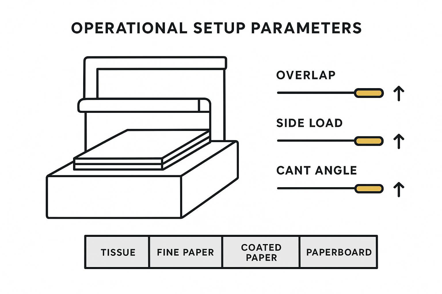
El papel se comporta de manera diferente según el grado: el papel tisú (tissue) puede rasgarse y deshilacharse bajo una carga lateral excesiva; los papeles estucados pueden vitrificarse cuando la interfaz se calienta; el cartón puede provocar vibraciones en el sistema si los portacuchillas no son rígidos.
El objetivo no es encontrar un único ajuste “perfecto”. El objetivo es estandarizar un rango inicial por grado, para luego verificar y documentar los ajustes que su máquina y portacuchillas puedan mantener de manera constante.
Rangos iniciales recomendados: tisú, papel fino, estucado, cartón
Use these as rangos iniciales, luego ajuste en pequeños pasos. La geometría de la cuchilla y el diseño del portacuchillas de su fabricante original (OEM) pueden desplazar la ventana óptima.
| Grado de material (ejemplo) | Solape (mm) | Carga lateral (lbf) | Ángulo de inclinación (°) | Riesgo típico si es demasiado agresivo |
|---|---|---|---|---|
| Papel tisú / papel suave | 0.3–0.6 | 1–2 | 0.25 | Arrugas, desgarros |
| Papel fino (ventana de inicio general) | 0.4–0.75 | 2–4 | 0.25–0.5 | Generación de polvo, desgaste del filo |
| Papel estucado ligero (LWC) | 0.4–0.8 | 1–3 | 0.25–0.5 | Polvo, calor, pulido del filo |
| Papel para etiquetas (label stock) | 0.5–0.8 | 1–4 | 0.25–0.5 | Acumulación de adhesivo |
| Cartón para cajas plegables | 0.8–1.2 | 3–6 | 0.5–0.75 | Aplastamiento de fibra |
| Duplex board | 1.0–1.5 | 4–8 | 0.5–0.75 | Edge delamination |
These are practical ventanas de inicio commonly used in converting. Definitions and optimal values vary by knife diameters, holder design, and web speed—verify at low speed and document your stable window by grade.
For an operator mindset on safe, repeatable slitter adjustments, Valmet’s guidance on positioning checks and systematic verification is a useful reference (Valmet: slitter adjustments).
Verification workflow: alignment, overlap, pressure, low-speed checks
A fast way to prevent “mystery burrs” is to verify the cutting system in the same order every time:
- Alineación: confirm knives track true to the web path; check holders for looseness.
- Superposición: set the target overlap, then confirm it holds across the shaft.
- Pressure / side load: increase only to the point you get stable contact without heat.
- Low-speed checks: run slow and inspect edges before going to production speed.
Done right, this turns setup into a controlled process instead of a trial-and-error loop.
Scaling with speed: adjust side load and cant conservatively
When you increase line speed, you usually need slightly more stability at the cutting point. Make changes conservatively:
- Increase side load in small steps and watch for temperature rise and glazing.
- Adjust cant angle only when the edge shows a clear failure mode (burrs, fuzzy edge, or uneven wear).
- Re-check runout and holder rigidity if vibration appears after a speed change.
Cuchillas circulares inferiores: selección de ingeniería
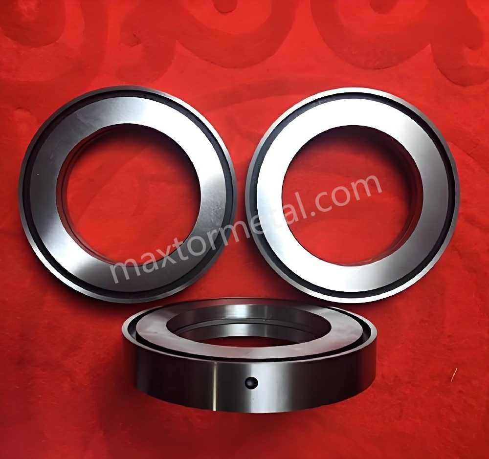
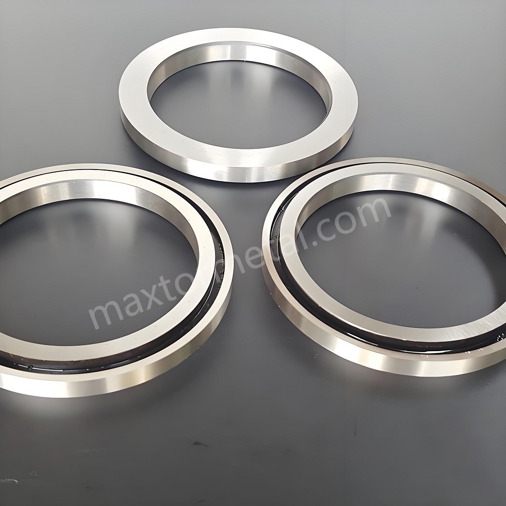
Bottom circular knives are doing two jobs at once: they provide the counter-edge and they keep the cutting point stable under side load and speed. Selection is mainly about matching material + hardness, edge geometry, y body geometry to your grade, speed, and uptime goals.
If you need a baseline overview of circular knife categories and common coatings across industries, MAXTOR METAL’s circular knives & blades page summarizes typical materials, coating options, and inspection checkpoints.
Materials and hardness: D2, M2, PM-HSS, carbide
Material selection should reflect what actually drives wear in your line:
- D2: good wear resistance and compressive strength for many converting applications; common choice when you want stable performance with predictable regrinds.
- M2 (HSS): higher hot hardness than D2; useful when heat at the edge is a recurring issue.
- PM-HSS: more uniform carbide distribution than conventional HSS; often chosen when you want improved wear consistency and fewer micro-chips.
- Carburo: excellent wear resistance and edge retention, but more brittle; it typically demands tighter runout control and stable holders to avoid chipping.
Rather than chasing maximum hardness, prioritize consistency: stable heat treat, verified hardness, and geometry that your setup can support.
Edge geometries: single/double/hollow, slim vs. standard
Edge geometry is where “burr-free” lives or dies.
- Single bevel geometries can be more forgiving in some setups, but they may concentrate load at the cutting point.
- Double bevel edges can balance the cut, but they require alignment and overlap discipline.
- Hollow-ground edges can reduce contact area and help with some grades, but they are more sensitive to damage and regrind quality.
For slim vs. standard bodies, consider stiffness and heat: slim profiles may reduce drag and dust in some systems, but a standard profile can be more stable when side load and speed rise.
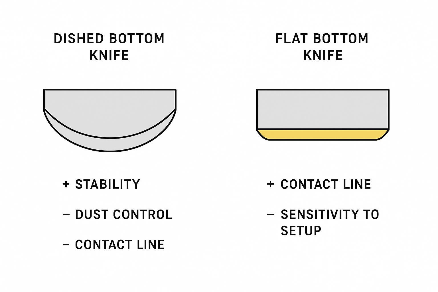
Dished vs. flat bottoms: selection by web and speed
Body geometry affects how the knife pair contacts and how forgiving the system is to small alignment errors.
- Dished bottom knives can help stabilize the contact line and reduce sensitivity in some high-speed, thin-web setups.
- Flat bottom knives are straightforward and widely used, but they can be less forgiving when holders or shafts have marginal rigidity.
The right choice depends on your web, speed, and how stable your holder stack-up is.
Tolerancias, acabado y control de calidad

Even a strong material and a good geometry can’t compensate for a knife that doesn’t run true. In shear slitting, tolerances determine whether the cutting point stays stable or “walks” as the knives rotate.
Runout, concentricity, and face parallelism targets
Your OEM’s specification is the authority, but these are typical targets many plants use as a starting point for stability. The key is controlling slitter knife runout so the cutting point doesn’t move as the pair rotates:
- Radial/axial runout (TIR): keep as low as practical for your speed; tighter targets reduce chatter risk.
- Concentricidad: the cutting edge should stay centered to avoid periodic load spikes.
- Face parallelism: consistent faces help you hold overlap and side load without creating hot spots.
If you see burrs that come and go at a fixed interval, treat it as a runout/concentricity clue before you change overlap.
A practical way to make these targets actionable is to tie them to line speed tiers (example bands below). Use them as internal control targets unless your OEM specifies otherwise.
| Velocidad de línea | Typical application | Radial TIR | Axial face parallelism | Concentricidad |
|---|---|---|---|---|
| Low speed (<150 m/min) | General paper / board | ≤0.03–0.05 mm | ≤0.02 mm | ≤0.03–0.05 mm |
| Medium speed (150–400 m/min) | Coated paper / film | ≤0.02–0.03 mm | ≤0.01–0.015 mm | ≤0.02–0.03 mm |
| High speed (>400 m/min) | Film / battery / precision foil | ≤0.01–0.015 mm | ≤0.005–0.01 mm | ≤0.01–0.02 mm |
Note: these are example control bands. Your knife diameters, holder stiffness, bearing condition, and inspection method (indicator setup) can shift what is achievable. Always follow OEM limits first.
Inspection and traceability: gauges, reports, and regrind records
Surface finish (roughness) and why it matters
Surface finish influences friction at the interface, which in turn affects heat generation, dusting, and pickup tendency (especially on coated grades and adhesive label stock). As a rule: improve geometry stability first, then use finish as a friction-control lever.
| Surface type | Typical recommendation |
|---|---|
| General paper slitting | Ra ≤0.4 μm |
| Precision foil / film | Ra 0.05–0.2 μm |
| High-speed coated materials | Highly polished finish recommended |
Track what matters for repeatability:
- Incoming material certification and heat/lot records
- Pre- and post-grind inspection results (runout, face parallelism)
- Regrind count, removed material, and restored edge geometry
MAXTOR METAL supports µm-level inspection reports, material certificates, and serial-based regrind records, and can build custom OEM replacements from drawings or samples to keep matched knife sets consistent.
Below are simple templates you can copy into your internal work instructions. Adapt fields and limits to your OEM spec and measurement method.
Example slitter knife QC checklist
| Inspection item | Objetivo | Resultado | Status |
|---|---|---|---|
| Radial TIR | ≤0.02 mm | ____ | PASS / FAIL |
| Excentricidad axial | ≤0.01 mm | ____ | PASS / FAIL |
| Face parallelism | ≤0.01 mm | ____ | PASS / FAIL |
| Acabado superficial | Ra ≤0.4 μm | ____ | PASS / FAIL |
| Edge condition | No chips / pickup | ____ | PASS / FAIL |
| Tolerancia de espesor | Within spec | ____ | PASS / FAIL |
| Holder cleanliness | Limpio | ____ | PASS / FAIL |
| Torque verified | Sí | ____ | PASS / FAIL |
Regrind record template
| Knife ID | Material | Original OD | Current OD | Recuento de remoldeo | Last run length | Observed wear |
|---|---|---|---|---|---|---|
| TK-2048 | Carburo | 220 mm | 216 mm | 4 | 28 km | Minor pickup |
| TK-2051 | HSS | 180 mm | 176 mm | 3 | 12 km | Edge rounding |
| TK-2055 | Carburo | 260 mm | 255 mm | 5 | 35 km | Stable |
Inspection frequency (typical)
| Inspection type | Typical frequency |
|---|---|
| Visual edge inspection | Cada turno |
| Burr verification | Every roll change |
| TIR verification | Weekly or after knife crash |
| Surface finish check | After regrinding |
| Full dimensional inspection | Every regrind cycle |
Finishing and coatings: mirror polish, TiN/TiAlN/CrN
Finishing and coatings should be selected for the failure mode you’re seeing, not as a default upgrade.
- Mirror polish can reduce friction and help on grades that tend to dust or heat.
- TiN / TiAlN / CrN coatings can improve wear resistance and reduce galling, but only if the base edge geometry and runout are already under control.
If coatings “fail fast,” it’s often a sign of heat, overload, or unstable contact rather than a coating problem.
Resolución de problemas de rebabas, polvo y vibración

Troubleshooting is fastest when you change one variable at a time and verify at low speed. DIENES’ overview of common shear slitting problems is a good reminder that dust is often an early indicator of a geometry or setup issue (DIENES: common problems).
| Síntoma que usted observa | Most likely root cause (first) | First checks (before changing settings) | Safe, reversible adjustments (one at a time) |
|---|---|---|---|
| Dusting / fuzzy edges | Cutting point not stable; overlap too high/low; dull or micro-chipped edge | Check knife damage under magnification; verify holder bearings; verify alignment and runout | Nudge overlap in small steps; increase side load only until stable contact (avoid heat); reduce cant if rubbing/heat appears |
| Burrs + glazing / heat tinting | Excessive side load, too much cant, finish mismatch, or rubbing from misalignment | Check temperature rise; check face parallelism; confirm contact line is progressive (not rubbing across full width) | Reduce side load first; then reduce cant slightly; verify overlap is not excessive; consider polish/coating only after geometry is stable |
| Chatter / vibration (especially at speed) | Runout, stack-up looseness, holder stiffness/resonance | Check spacers/stack tightness; re-check radial/axial runout; inspect shafts and bearings | Reduce side load; back down speed to confirm resonance; correct runout/stack-up before increasing overlap or cant |
Tip: if edge quality varies cyclically (good–bad–good at a fixed interval), treat it as a runout/concentricity/stack-up clue before changing overlap or pressure.
Dusting and fuzzy edges: overlap, side load, and edge sharpness
If you see dusting or a fuzzy edge, start with the cutting point and contact stability:
- Reduce overlap slightly if fibers are being torn rather than sheared.
- Increase side load only until contact is stable; avoid crushing the interface.
- Inspect edge sharpness and micro-chipping; a “sharp-looking” edge can still be damaged at the micro level.
Also check holder bearings and shaft rigidity before chasing parameter changes.
Burrs and glazing: cant angle, heat, and finish mismatch
Burrs and glazing often show up together when the interface runs hot.
- Add or refine cant angle only in small steps to get a progressive cut.
- Reduce side load if you see heat tinting, glazing, or rapid edge rounding.
- Match finish/coating to the grade: a rougher finish can increase friction on sensitive coatings and make glazing more likely.
Chatter and vibration: alignment, runout, and holder stability
Chatter is typically a system stiffness problem first, and a knife problem second.
- Verify alignment and stack-up: loose spacers and unstable holders create periodic vibration.
- Re-check runout before increasing side load.
- If vibration starts only at higher speed, step back and confirm the holders can support the new speed without resonance.
Conclusión
- Standardize parameters by grade and document verified settings
- Select materials/geometries to match speed, grade, and uptime goals
- Inspect tolerances, finish, and track regrinds to extend tool life
Referencias (seleccionadas)
- DIENES: Dust generation caused by the shear angle, cutting point and the geometry of the knife and system — https://www.dienesusa.com/dust-generation-caused-by-the-shear-angle-cutting-point-and-the-geometry-of-the-knife-and-system/
- Valmet: Slitter adjustments (positioning checks and systematic verification) — https://www.valmet.com/insights/articles/up-and-running/performance/SlitterAdjustments/
- Carolina Knife: Principles of shear slitting (definitions of overlap/penetration and typical side load ranges) — https://www.carolinaknife.com/wp-content/uploads/2020/07/Principles_of_shear_splitting-1.pdf
Nancy Wu — Senior Manufacturing Engineer, Production Engineering (PE). 12 years of experience in industrial blade manufacturing and grinding, with deep familiarity in D2, M2, H13, PM steels, and carbide processing and coating behavior. Skilled in high-precision CNC grinding programming.
Certifications: SME–CMfgE, PMP, Six Sigma Black Belt, ASM International Certifications.
FAQs
What causes burrs in paper shear slitting?
Burrs usually come from an unstable cutting point: too much overlap, excessive side load, incorrect cant angle, or runout that moves the shear interface. Start by verifying alignment and runout, then adjust overlap and cant in small steps.
How do I set overlap and side load for tissue vs. paperboard?
Start conservatively for tissue (low overlap and side load to avoid tearing) and increase both for paperboard only as the holder stack-up allows. Always validate at low speed and document the stable window for each grade.
What is cant angle (toe-in) and how does it affect dusting?
Cant angle makes the cut progressive across the web. Too little cant can increase tearing and dusting on some grades; too much can drive heat and uneven wear. Tune cant after overlap and side load are stable.
When should I choose a dished bottom circular knife instead of a flat one?
Choose dished bottoms when you need a more forgiving contact line at higher speeds or on thinner webs, especially if small alignment variation is hard to eliminate. Flat bottoms work well when holders and shafts are rigid and runout is tightly controlled.
Which material is best for bottom circular knives: D2, HSS, PM-HSS, or carbide?
There isn’t one best material. D2 is a common baseline; HSS/PM-HSS can handle heat and wear more consistently; carbide offers strong wear resistance but needs tighter runout control to avoid chipping. Match the material to your dominant wear mode and holder stability.
What tolerances matter most for burr-free slits?
Runout (axial and radial), concentricity, and face parallelism matter most because they keep the cutting point stable. If edge quality varies cyclically, treat it as a tolerance/holder issue before changing overlap.
How do I reduce dust without overloading the knives?
Verify the cutting point first: correct alignment, minimal runout, and a sharp, undamaged edge. Then tune overlap and side load in small increments, and keep cant angle only as high as needed for a progressive cut.

 English
  Spanish
  Italian
  French
  Portuguese
  Russian
  German
  Arabic
  Hindi
Hindi  Vietnamese
  Indonesian
  Japanese
  Korean