
High-speed vibration robs you of uptime and quality. On rotary cutters, even a few tenths of a gram out of place can turn into jarring forces at operating RPM, showing up as chatter marks, tails and fines, premature knife wear, bearing heat, and rising scrap. Static balance helps with heavy spots in one plane, but it cannot correct couple unbalance that shows up at speed.
Two-plane dynamic balancing addresses what static balancing misses. By measuring amplitude and phase at both bearings, then solving for correction masses in two planes, you can reduce residual unbalance to a defined tolerance and keep vibration within healthy ranges.
In this article, you will learn how to choose an ISO 21940 balance grade, compute e_per and U_per with a clear numerical example, and run the influence-coefficient workflow step by step—both in a shop balancer and in the field. Maintenance teams, OEMs, and production managers will find practical targets, formulas, and acceptance checks they can apply immediately.
Conclusiones clave
- Two-plane dynamic balancing fixes couple unbalance that static methods cannot, cutting vibration at service speed.
- Use ISO 21940 balance grade to translate a quality grade (G) into a permissible residual unbalance U_per you can verify.
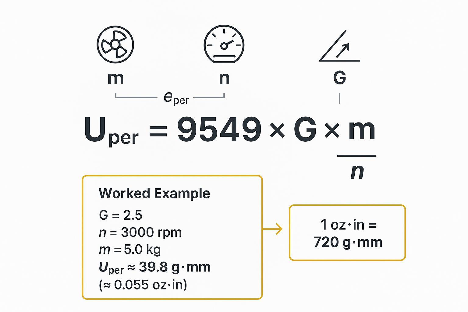
- Core formula you’ll use: U_per (g·mm) = 9549 × G × m / n. A G2.5, 5.0 kg rotor at 3000 rpm → U_per ≈ 39.8 g·mm (≈0.055 oz·in).
- Accept with two gates: residual unbalance per plane within target and overall vibration velocity within ISO 20816 Zone B or better across the operating range.
- Rebalance after regrinds, knife changes, stack shifts, or if vibration trends creep above your limits.
Why Balance Rotary Cutters
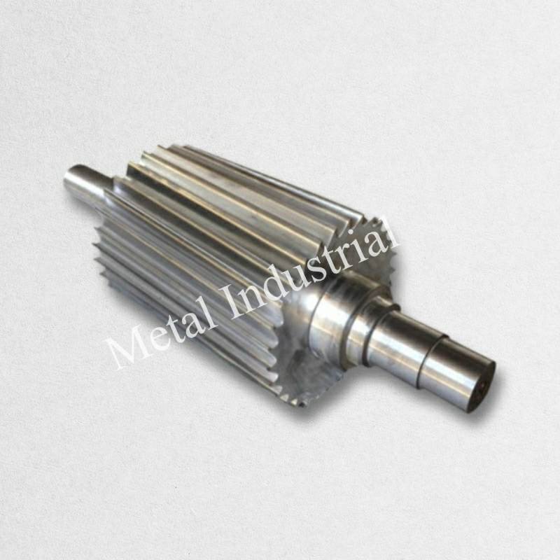
Causes of High-Speed Vibration
Unbalance is the most common driver: mass eccentricity from knife wear, uneven regrinds, swarf buildup, hub runout, or tolerance stack-up. Couple unbalance appears when mass is displaced in opposite senses across planes—static checks miss this. Other contributors include misalignment, bent shafts, looseness, and resonance near operating speed, but unbalance is usually the first lever to pull back vibration.
Measurable Performance Gains
Reducing residual unbalance lowers dynamic forces on bearings and frames, cutting noise, heat, and wear. In pelletizing and converting lines this translates to steadier cut length, fewer tails and fines, longer knife life between regrinds, and higher OEE. Think of it this way: every gram·millimeter you remove is one less tiny hammer blow each revolution.
When to Rebalance
- After any knife change, regrind, or stack/holder rebuild
- After bearing or coupling work
- When overall vibration velocity climbs a zone (e.g., from A to B) or phase becomes unstable near setpoints
- After incidents: rubs, jams, or strikes
- On a calendar/throughput basis if your process is abrasive or high-fill
Standards and ISO 21940 Balance Grade
Selecting a Balance Quality Grade
Selecting an ISO 21940 balance grade sets a measurable target for residual unbalance. For industrial rotary cutters, common choices are:
- G2.5 at mid-to-high speeds when you want tight quality without spindle-level precision
- G6.3 for slower, heavier rotors where precision is less critical
- G1.0 for high-precision toolholding at very high speeds
ISO 21940‑11 (which supersedes ISO 1940‑1) is the common reference for rigid-rotor balance quality grades and the method used to derive permissible residual unbalance targets. For practical selection guidance and terminology, see the EASA service-center overview and BalanceMaster’s grade explainer.
- According to the EASA service-center overview (2016), ISO 21940‑11 defines balance quality grades and the math to derive permissible residuals. How the ISO 21940‑11 balance quality grade standard impacts service-center balancing
- For a practitioner-grade summary of where G1.0/G2.5/G6.3 fit, see BalanceMaster’s explainer. ISO balancing grades explained
Calculating eper and Uper
Use the ISO-derived relationship many authoritative sources reproduce:
U_per (g·mm) = 9549 × G × m / n
Where G is the selected grade (mm/s), m is rotor mass (kg), and n is service speed (rpm). Conceptually, U_per = e_per × m, and for a given grade, e_per decreases as speed increases.
Worked example (G2.5 @ 3000 rpm):
- Given: m = 5.0 kg, n = 3000 rpm, G = 2.5
- Compute: U_per = 9549 × 2.5 × 5.0 / 3000 ≈ 39.8 g·mm
- If a single-plane equivalent were applied at radius r = 75 mm, the mass at that radius would be m_c = U_per / r ≈ 39.8 / 75 ≈ 0.53 g (two-plane distribution follows the influence matrix solution).
- Convert to imperial: 1 oz·in = 720 g·mm → 39.8 g·mm ≈ 0.055 oz·in
Quick comparisons (same formula):
- G6.3 @ 1800 rpm, m = 12 kg → U_per ≈ 9549 × 6.3 × 12 / 1800 ≈ 401 g·mm (≈0.557 oz·in)
- G1.0 @ 6000 rpm, m = 2.0 kg → U_per ≈ 9549 × 1.0 × 2.0 / 6000 ≈ 3.18 g·mm (≈0.0044 oz·in)
Cross-check your numbers with an authoritative calculator that implements ISO 21940‑11 relationships. See Vibromera’s residual unbalance calculator. Residual unbalance calculator (ISO 21940‑11)
KPIs and Acceptance Targets
- Residual unbalance per plane: Allocate the total U_per across planes using the influence coefficients (often similar if geometry is symmetric). Record the final correction masses and angles; compute residuals to confirm they meet the selected grade at the target RPM.
- Overall vibration velocity: Check bearing-housing velocity (RMS). As a practical target, many shops accept Zone B or better per ISO 20816 for the relevant machine group and foundation class. Nota: the numeric zone boundaries depend on the ISO 20816 part/table and the machine group/foundation, so verify the applicable limits against the standard and your OEM manual. See the Mobius Institute reference summary of ISO 20816 zones. ISO 20816 vibration zones summary
- Phase stability and sweep: Verify phase remains stable across the operating range and no resonance peaks dominate near set speed.
Two-Plane Balancing Procedures
Shop Balancing (Two-Plane)
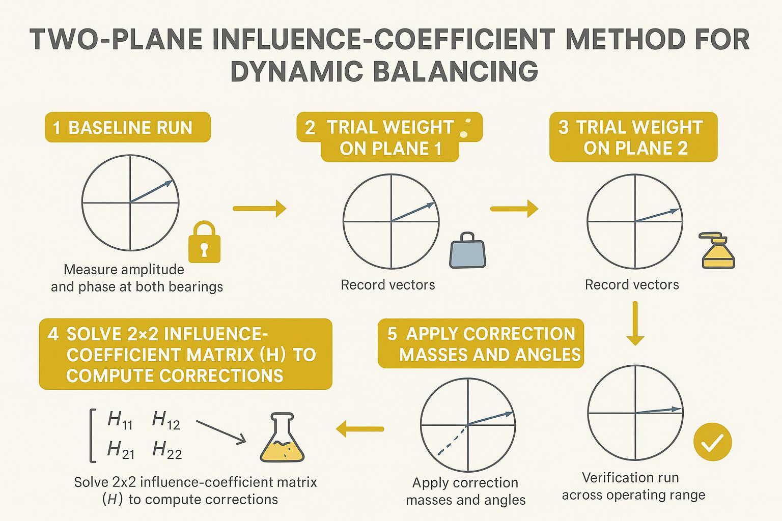
A typical two-plane workflow uses a calibrated balancing machine and the influence-coefficient (trial-weight) method: capture a baseline at target speed, run a trial in Plane 1, run a trial in Plane 2, solve the 2×2 influence matrix for correction vectors, apply masses/angles, and verify residuals.
Safety note (read before you run): Balancing work can cause severe injury or equipment damage if a rotor, trial weight, or guard fails. Only qualified personnel should perform these steps. Follow your site lockout/tagout (LOTO) procedure before installing/removing weights, keep guards in place whenever possible, and use redundant, positively retained trial weights (no tape-only mounting). Verify clearances, torque fasteners to spec, and stay outside the plane of rotation during run-up and coast-down.
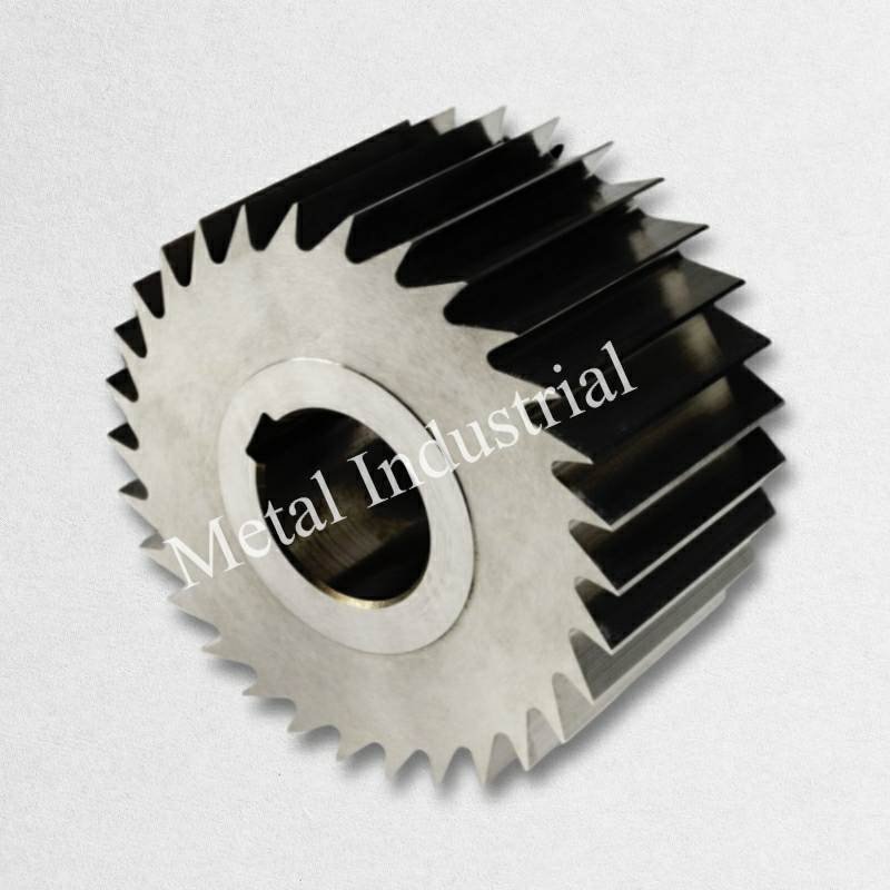
If you source OEM/ODM knives, a neutral example is helpful: MAXTOR METAL manufactures custom, precision-ground blades and offers factory dynamic balancing and concentricity checks prior to shipment. In practice, this means rotors can be balanced to ISO 21940 grade targets with a traceable report of the correction steps and measured residuals. For context on their balancing and concentricity practices, see the company’s overview page. High-speed dynamic balancing and concentricity
Key shop steps
- Preparation: Inspect rotor geometry, clean seating faces, confirm runout, and secure fixtures. Index a tach reference mark.
- Baseline: Measure amplitude and phase at both bearings at the defined service speed; record vectors.
- Trials: Add a known trial mass at a known angle in Plane 1; remeasure. Remove it, then repeat in Plane 2; remeasure.
- Solve: Use software or manual vector math to invert the 2×2 influence matrix and compute per-plane correction masses/angles.
- Verify: Apply corrections and repeat the run to confirm residuals within U_per targets and vibration in your acceptance zone.
Field Balancing (In‑Situ)
Field (in‑situ) balancing corrects the assembled system without disassembly. You will need a phase-referenced tach, two accelerometers or velocity sensors on the bearing housings, safe access for trial weights, and lockout-tagout procedures.
Safety note (read before you run): In-situ balancing exposes people to rotating equipment hazards. Use LOTO for any hands-on work, confirm guarding and exclusion zones, and secure trial weights with mechanical fasteners plus a secondary restraint. Do not exceed the machine’s rated speed, and stop immediately if rub, unusual noise, rising bearing temperature, or sudden phase instability appears.
- Baseline: At or near service speed, capture amplitude and phase on both bearings. Check soft foot and structural looseness first.
- Trial sequence: Add a safe, restrained trial in Plane 1; remeasure both bearings; remove and repeat for Plane 2.
- Solve and apply: Compute correction vectors and install permanent weights or adjust screws at the calculated angles/radii.
- Verification: Sweep through the operating range to ensure no resonance amplification; accept once both residual unbalance per plane and vibration velocity targets are met.
For a practical coding example of the influence-coefficient approach, National Instruments publishes a two-plane DAQmx example implementing the same sequence with phasors and tach indexing. Two-plane balancing example with DAQmx
Instrumentation notes (for repeatable phase and amplitude): Use the same sensor type and orientation on both bearing housings (velocity is often preferred for ISO 20816 comparisons). Rigidly mount sensors (stud or strong magnet on a clean, flat spot), keep cable routing consistent, and use a reliable tach/keyphasor reference tied to the rotor. Confirm instrument calibration is current, and record the measurement band and filter settings so follow-up checks are comparable.
Pitfalls and Safety Checks
Common “what you’ll see” signals and what to check first:
- Phase wanders or flips between runs: re-check tach/keyphasor pickup, sensor mounting stiffness, looseness/soft foot, and whether a resonance is dominating the response.
- Trial response is too small or non-linear: increase/decrease trial weight to target ~30–70% change from baseline, and verify the trial radius/angle reference is repeatable.
- Big amplitude peak near set speed: do a controlled sweep to identify resonance and avoid balancing exactly at the peak; change speed, stiffness, or damping first, then rebalance at a stable speed point.
- Rigid vs flexible rotor: If a critical speed lies near the operating point, rigid-rotor assumptions may fail; consult the relevant parts of ISO 21940 for flexible-rotor methods.
- Applicability boundary: If the rotor behaves as a flexible rotor at or near service speed (e.g., operating near a critical speed), do not force a rigid-rotor two-plane solution—follow the appropriate ISO 21940 method for flexible rotors and confirm acceptable speed ramps and run conditions with the OEM.
- Inconsistent influence coefficients: Re-run trials; verify sensor polarity, tach position, looseness, and mounting repeatability. Adjust trial mass so the response changes ~30–70% from baseline.
- Geometry and restraint: Secure trial weights redundantly, confirm guards and clearances, and avoid rubbing. Lockout-tagout and follow site procedures.
- Maintenance tie-in: After regrinds or knife swaps, expect balance to drift. A maintenance guide for granulator blades offers practical regrind pointers that pair well with a rebalancing check. Maintain and sharpen plastic granulator blades
Conclusión
- Confirm that residual unbalance in each plane meets your selected ISO 21940 balance grade at the target RPM using the ISO relationship.
- Verify vibration velocity across the operating range (aim for ISO 20816 Zone B or better) and document amplitude/phase and correction data.
- Schedule rebalancing after regrinds, knife changes, hub or bearing work, or when trends rise above limits.
- Capture a traceable balance report and trend results for reliability. For readers who need supplier context, the MAXTOR METAL overview of dynamic balancing and concentricity provides an example of what to request from a shop. High-speed dynamic balancing and concentricity
References (selected): ISO 21940‑11 overview via EASA; ISO grade selection summary via BalanceMaster; ISO residual unbalance cross-check via Vibromera calculator; ISO 20816 zone bands summary via Mobius Institute; two-plane influence-coefficient implementation example via National Instruments (DAQmx). (Links are provided in the sections above.)
What to capture in a traceable balance report (copy/paste checklist): Rotor ID/serial, configuration (knives/holders installed), rotor mass metro, correction radius o, service speed n, selected ISO 21940 balance grade G, computed U_per, sensor locations and orientation, tach reference location, instrument model + calibration date, measurement band/filtering, baseline amplitude/phase at each bearing, trial weight mass/angle/radius for Plane 1 and Plane 2, calculated correction mass/angle/radius per plane, final verification amplitude/phase, final residual unbalance estimate per plane, and an operating-speed sweep result (pass/fail vs your ISO 20816 velocity target).
About the author: Tommy Tang is a Senior Sales Engineer at Nanjing METAL Industrial with 12 years of experience supporting industrial cutting and rotating-equipment applications. Certifications: CSE, CME, Six Sigma Green Belt, PMP.