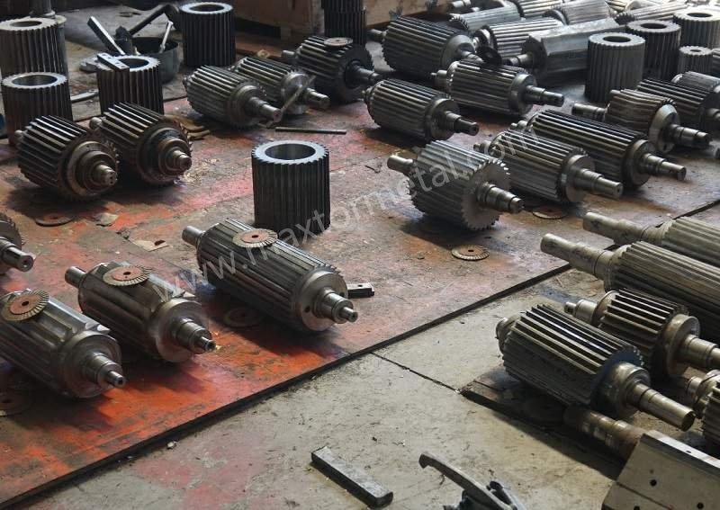
In strand pelletizing, polymer strands are guided into a rotary cutter that shears them against a fixed bed knife to create consistent pellets. A helical rotary cutter uses spiral knives rather than straight edges, so the cut occurs progressively along a helix instead of across the full width at once. At high RPM, this progressive shear spreads the cutting load over time, dampening force spikes that would otherwise excite vibration and tonal noise. Plants see practical wins from this mechanism: steadier pellet length distribution and edges, fewer fines, and longer service intervals when setup and maintenance are executed correctly.
Why this matters for speed: when a cutter engages all at once, the motor and structure feel sharp impulses in a repeating pattern, which can line up with machine natural frequencies and produce a recognizable “whine.” By contrast, the helical engagement keeps the contact zone small and moving, which tends to smooth torque demand and reduce harmonic excitation. In short, quieter often follows from smoother force input.
According to public OEM documentation for premium strand and underwater systems, operator‑position noise targets are often kept below 85 dB(A) at the system level, with cutting‑gap accuracy called out as a key enabler. This is a reference point for what modern systems aim to achieve—not a statement of how much any single component (such as the rotor or knives) contributes. For context on noise expectations and the emphasis on cutting‑gap setting, see MAAG’s system brochure: MAAG M‑USG, operator‑position sound and cutting‑gap focus.
Safety note: Any work involving guards, knife settings, or speed changes should follow your OEM manual, local EHS procedures, and Lockout/Tagout requirements, and be performed by qualified personnel.
Conclusiones clave
- Progressive shear spreads engagement over time, lowering instantaneous force and reducing tonal noise drivers at high RPM; this supports steadier pellets and fewer fines when the gap is controlled.
- Gap control is the daily lever: set a minimal, uniform knife‑to‑bed clearance per OEM guidance; verify cold and hot; re‑gap when pellet quality metrics drift.
- Balance and runout matter at speed: specify rotor balancing per ISO 21940 and keep assembly runout in micrometer ranges defined by your OEM to avoid forcing and chatter.
- Validate changes with KPIs you already track: dB(A) at operator position, fines percentage, and pellet length Cpk; log current ripple or vibration velocity if sensors are available.
- For abrasive or recycled feeds, choose wear‑resistant steels or coatings; pair regrind strategy with documentation so geometry and balance stay within limits over multiple cycles.
Mechanism & high-speed gains
Progressive engagement
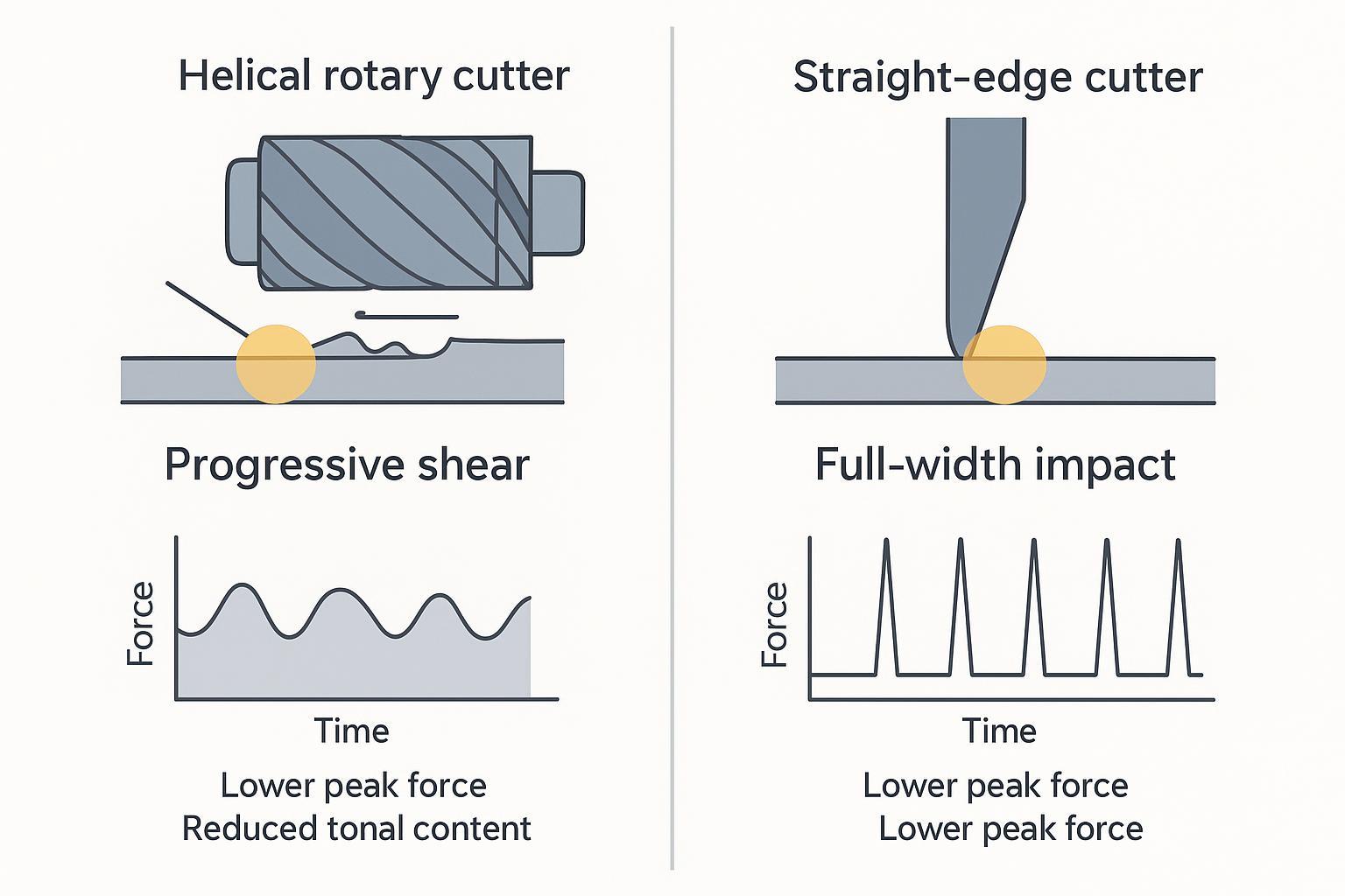
A helical rotary cutter engages the bed knife along a moving line rather than a full‑width strike. At any instant, only a small portion of the edge is shearing. Think of it as “handing off” the work along the helix. The contact zone enters, does work briefly, and exits—avoiding the single, broad impulse that can excite structure‑borne noise and elevate motor amperage peaks. In strand pelletizing, this translates to a calmer cut on each strand and fewer opportunities for tails when the clearance is set correctly.
Force and harmonics
Cutting force is never truly steady, but its waveform can be shaped. With straight knives, the force can arrive in tall, periodic spikes as each edge strikes across the full face. With a helical edge, the energy is partitioned into smaller, staggered increments, reducing peak magnitude and concentrating less energy at a single tone. That shift in the force spectrum is why helical cutters often sound less “tonal” at speed. It also reduces the likelihood of coupling with machine natural frequencies.
If your facility measures motor current or vibration, you’ll often see smaller amplitude ripples with a well‑balanced helical rotor and a uniform, tight gap compared with an equivalent straight‑edge setup—all else equal. System‑level noise targets referenced by OEMs (for example, the MAAG reference above) are generally compatible with this mechanism when enclosure design, strand guides, and installation quality are also optimized.
Geometry basics
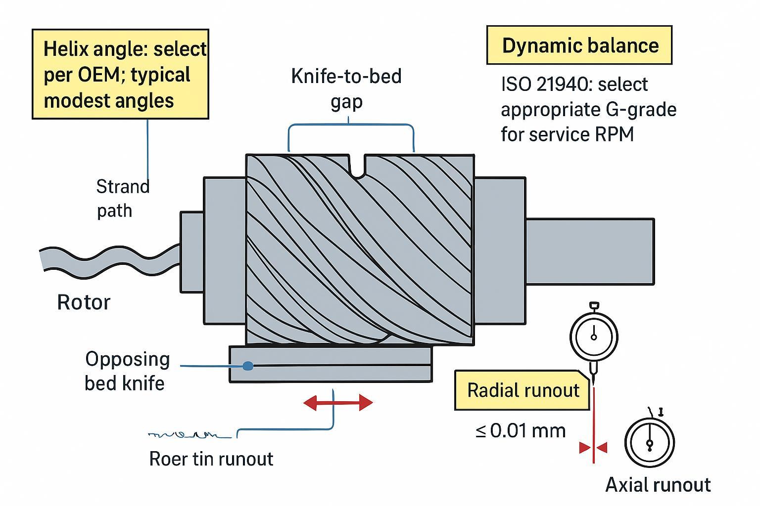
- Helix angle: Modest helix angles in polymer cutting help balance smooth shear against added axial (thrust) load. Higher angles tend to smooth engagement but can increase axial forces and edge stress. Select within your machine’s thrust capacity and polymer behavior per OEM guidance.
- Edge geometry: Edge land and included angle influence startup bite, fines generation, and life. Follow OEM or supplier recommendations for your resin family, fillers, and throughput.
- Knife count and wrap: More cutting events per revolution can raise base frequency but lower per‑event force; exact trade‑offs depend on rotor diameter, speed, and strand count.
For an accessible primer on progressive shear and pelletizer knife roles, see this educational overview: Masterbatch pelletizer blades guide (context).
Specification & setup
A quiet, stable helical installation is built on specification discipline and repeatable setup. That means defining the cutting gap, balance quality grade, assembly runout, and the regrind plan—and proving each with documentation.
Suppliers that support production QA can simplify this work. For example, MAXTOR METAL can provide material and hardness data with dimensional inspection records and, upon request, balancing and runout test reports aligned to buyer acceptance criteria. Keep such documents with your line’s maintenance files to speed audits and troubleshooting.
Key specifications
- Knife‑to‑bed gap
- Target a minimal, uniform clearance per your OEM. Premium underwater/strand systems emphasize precise, repeatable gap setting to stabilize pellet quality and noise. Public documentation highlights the importance of “cutting gap setting” rather than prescribing a universal value; always defer to the machine manual. See the OEM perspective here: MAAG M‑USG, emphasis on cutting‑gap accuracy.
- Dynamic balance (ISO 21940)
- Specify rotor balancing to ISO 21940 with an appropriate G‑grade for the service RPM and sensitivity of your cutter/line. High‑speed, precision cutting applications commonly require tighter grades; confirm the grade and verification method with your OEM and supplier.
- Runout (assembly and installed)
- Control radial and axial runout to OEM‑specified micrometer limits. Measure on the rotor journals/knife faces with dial indicators and re‑verify after regrinds and reassembly. Even small increases in runout can widen effective gap, elevate fines, and add tonal content.
- Materials and coatings (for abrasive/recycled feeds)
- For glass‑filled or high‑recycle blends, consider powder‑metallurgy tool steels or carbide‑tipped knives, and coatings such as TiN/TiAlN or chromium to reduce friction and wear. Match hardness and coating to your coolant/wet environment as applicable. For an educational overview of blade materials in plastics service, see this context piece: Industrial blades for plastic processing.
Setup and gap control
A simple, repeatable SOP improves noise and quality as much as a new rotor. Below is a model‑agnostic procedure—adapt specifics (torques, gauges, target clearances) to your OEM manual.
- Preparation (Lockout/Tagout, cleanliness)
- Lockout the drive. Clean rotor and bed‑knife seating faces. Install matched, sharpened knives; verify fasteners and keys.
- Cold alignment and initial gap
- Set the bed knife using your OEM’s mechanism (commonly push/pull bolts on the bed‑knife holder, or eccentric adjustment depending on model). Aim for a minimal, uniform clearance. Check multiple positions along the cut line with feeler or leaf gauges appropriate to your model. Sweep parallelism with a dial indicator across the bed‑knife face; correct taper. For publicly available examples of these adjustment concepts, see Bay Plastics Machinery’s strand‑pelletizing training material (push/pull gap adjustment) and MAAG’s T200 series overview (eccentric rotor‑to‑bed adjustment): BPM Training PDF, MAAG T200 series.
- Balance/runout verification
- If the rotor was serviced, review the latest ISO 21940 balance certificate and measure installed radial/axial runout at specified points. Record values on the job traveler.
- Hot verification
- Warm the line to operating temperature and RPM under typical load. Stop safely and recheck accessible points (or use in‑situ gauges if designed) to account for thermal growth. Adjust per OEM guidance if a “hot” target clearance is specified.
- Acceptance checks
- Resume production and observe pellet edges, fines percentage, and motor current ripple. If tails, sudden fines, or tonal noise rise, re‑inspect for contamination under the bed knife, gap drift, or edge wear.
For background on system‑level expectations (operator‑position noise) and the importance of accurate cutting‑gap setting, see the MAAG reference cited earlier.
Troubleshooting quick matrix
| Symptom you see/hear | Likely cause (most common first) | What to do next (in order) |
|---|---|---|
| More fines / dusty pellets | Gap opened up, edge dulling, contamination under bed knife | LOTO → clean seating faces → re‑set gap cold → verify at multiple positions → inspect edge land/chips |
| Tails or inconsistent length | Gap non‑uniform (taper), runout increased, strand guide misalignment | Check parallelism with dial indicator → check runout at OEM points → correct taper → verify strand guides |
| Rising tonal “whine” at steady RPM | Balance drift after service, runout growth, resonance excited by forcing | Review last balance cert → measure vibration/current ripple trend → re‑verify runout → correct unbalance per ISO 21940 plan |
| Motor current ripple increases | Intermittent contact from runout or gap drift, uneven knife set | Confirm matched knife set and fastener torque → re‑gap hot if required → re‑check runout |
| Noise rises but pellets look OK | Enclosure/guide changes, airflow paths, measurement point changed | Confirm measurement position/time window → inspect guards/enclosure panels and strand guide section for looseness |
Always follow your OEM manual and EHS procedures; do not bypass guards or adjust settings on a running machine unless the equipment is explicitly designed for in‑situ adjustment.
Regrind and wear
Edge wear widens the effective gap and elevates fines and noise. Keep geometry within limits and document each cycle.
- Triggers: Regrind when fines and tails exceed your internal limits, when length Cpk trends down, or at the OEM’s edge‑land threshold.
- Balance after service: If mass was removed asymmetrically, rebalance the rotor per your specified ISO 21940 grade.
- Rotation strategy: Rotate knives/edges as prescribed to distribute wear.
- Records: Log hours/throughput, gap checks, geometry after grind, balance cert numbers, and runout readings. This history speeds root‑cause work if quality drifts.
Validation & procurement
KPIs and trials
Treat changes like engineering trials. Change one variable at a time, then measure in steady state.
- Noise: Measure dB(A) at operator position using your plant’s method aligned with the ISO 11200 family for machinery noise in situ; compare to your site targets and OEM expectations (e.g., modern systems often target <85 dB(A) at the operator position per MAAG M‑USG).
- Product quality: Sample fines percentage by sieving at timed intervals after warm‑up. For pellet length, compute Cpk from a defined sampling plan (e.g., multiple pulls over 30–60 minutes) and track alongside gap/balance notes.
- Machine health: Where available, log motor current ripple and vibration velocity (mm/s). Look for reductions in peak‑to‑peak and tonal components when gap/runout are tightened.
Documentation checklist
Provide and retain documents that prove what you specified is what you received and installed. The items below are commonly requested in audits and RFQs.
| Document | Objetivo | Notes/Standard |
|---|---|---|
| Material test certificate | Confirms grade/chemistry and test results for the batch | Prefer EN 10204 3.1 for traceability; overview: TWI—material test certificates / EN 10204 context |
| Hardness report | Verifies HRC or HV at defined locations | Include method, location map, acceptance range |
| Dimensional inspection | Confirms critical dimensions, flatness, and parallelism | Attach drawing with tolerances; include surface finish where relevant |
| Dynamic balance certificate | States ISO 21940 grade and service RPM used | Include final residual unbalance and correction planes |
| Runout report (assembly/installed) | Documents radial and axial runout at specified points | Record measurement setup and indicator positions |
| Coating specification (if used) | Identifies coating type and thickness | Note process (PVD/CVD/plating) and post‑treatments |
| Regrind/maintenance record | Tracks geometry, balance, and life over cycles | Link to serial/heat numbers for traceability |
Compatibility and lead time
Avoid surprises by confirming geometry and interfaces up front.
- Geometry and interface: Confirm helix direction/angle per OEM, edge geometry, hole/slot pattern, keyways, and thickness/diameter. Share a controlled drawing and, if possible, a sample or detailed photos.
- Balance/runout acceptance: Put ISO 21940 G‑grade, measurement planes, and runout limits in the PO; define how acceptance will be verified at your site.
- Regrind rotations: Plan inventory so a freshly ground, documented set is always ready when the running set hits its trigger. Align supplier lead times with your maintenance window.
Example trial log (fill-in template)
Use this as a one-page record for an A/B change (e.g., “tighten gap SOP,” “freshly reground knives,” or “new helical rotor”). Keep the test window and measurement method consistent.
| Categoría | Fields to record | Notas |
|---|---|---|
| Noise measurement | Location (operator position), distance, instrument/model, weighting (A), averaging/time window, background noise notes | If you use an ISO 11200-family method on-site, note the specific procedure your EHS team follows |
| Operating condition | Resin grade, filler/recycle %, throughput, RPM, cooling method, strand count | Record only what materially changed |
| Cutting settings | Knife‑to‑bed gap (cold), knife‑to‑bed gap (hot/steady state, if applicable) | Always record units and where along the cut line it was checked |
| Machine health | Radial/axial runout readings (points used), vibration (mm/s) if available, motor current ripple method | Reference the same measurement points every time |
| Quality KPIs | Fines % method (sieve mesh/time), pellet length sampling plan, pellet length Cpk, visible defects (tails, chips) | Attach the sampling sheet if you have one |
| Maintenance record | Knife set ID/serial, regrind count, key geometry notes, balance certificate ID (ISO 21940), runout report ID | This is what makes results auditable and repeatable |
Conclusión
Progressive helical engagement reduces peak cutting force and tones that excite structures at speed. When you pair that mechanism with disciplined specifications (tight, uniform gap; proper balance; low runout), plants typically see the outcomes that matter: lower perceived noise at the operator position, reduced fines percentage, and a healthier pellet length Cpk. The risk is managed—not by hope—but by written specs, SOPs, and documented QA, then validated with structured trials and routine measurements.
For abrasive and recycled feeds, select materials and coatings that resist wear in your environment, and maintain balance/runout through each regrind cycle. If you build that loop—specify, verify, record, and adjust—you’ll get the quiet, stable high‑speed cutting your strand pelletizing lines were designed to deliver.
About the author: Tommy Tang is a Senior Sales Engineer at Nanjing METAL Industrial with 12 years of experience supporting industrial blade applications. Certifications: CSE, CME, Six Sigma Green Belt, PMP.
Methodology and scope: This guide synthesizes publicly available OEM documentation (for example, MAAG system brochures), common plant KPIs (dB(A), fines %, pellet length Cpk, current ripple/vibration), and standard terminology (e.g., ISO 21940 for balancing). Specific clearances, torques, and acceptance limits are machine‑model dependent—use your OEM manual and site EHS procedures as the governing reference.