


Risposta rapida: Catastrophic blade shattering is almost never one cause—it’s the convergence of metallurgical defects (retained austenite, carbide banding), thermal-process errors (quench cracks, insufficient temper), and geometric stress risers, triggered by a contamination event. Fractography (macro mapping → SEM/EDS → metallography → XRD) identifies which lever failed; supplier controls like AMS 2750 pyrometry and lot-level RA measurement prevent recurrence.
When a shredder blade shatters mid-operation, the consequences are immediate and expensive. Fragment ejection creates safety exposure for maintenance crews; the shredder line halts while operators locate every piece of debris; and emergency tooling procurement can cost multiples of what a planned replacement would. In scrap-metal and municipal solid-waste processing, where throughput is measured in cost-per-ton, an unplanned stop lasting even two hours can erase an entire shift’s margin.
Industriale shredder blades and shredding knives are engineered for toughness under high-impact cyclic loading — but catastrophic brittle failure still occurs at facilities that have done everything else right. The cause is almost never a single event. It is the convergence of metallurgical defects, thermal-process deviations, geometric stress concentrators, and contamination loading — each individually tolerable, collectively lethal to the tool.
This article connects those root causes to their physical mechanisms, defines the lab workflow that confirms them, and translates the findings into supplier controls and incoming-inspection criteria that prevent recurrence.
Nota informativa: This guide is published by Maxtor Metal, a manufacturer and supplier of custom, precision-ground industrial blades. While the technical content is written to be accurate and is drawn from published ASTM, AMS, ASM, and AIAG standards, readers should be aware of this commercial interest. Maxtor Metal products are referenced where relevant; where a supplier-agnostic approach is possible, we note it.
Failure Physics

Brittle Fracture Mechanics in Knives
Wear and brittle fracture are fundamentally different failure modes, and conflating them leads to the wrong corrective action. Wear removes material from the cutting edge progressively and predictably; brittle fracture propagates a crack through the blade body in microseconds once a critical stress intensity factor (K Ic) is exceeded.
High-chromium cold-work and tool steels used in shredder knives — typically conforming to ASTM A681 or DIN EN ISO 4957 grade D2/D3 equivalents — carry very high carbide volume fractions. Those carbides are essential for abrasion resistance, but they also reduce fracture toughness. A steel with 60–64 HRC surface hardness and 12–14% Cr may have a K Ic as low as 14–22 MPa√m, meaning the margin between safe operation and through-cracking is narrow. Any pre-existing crack, void, or notch reduces the effective toughness further.
Key principle: Brittle fracture in knife steels is a threshold phenomenon. Below K Ic, cracks do not propagate. Above it, propagation is instantaneous. Reducing the number and severity of crack initiators is therefore more effective than chasing marginal hardness gains.
Stress Risers and Geometry/Fit Effects
Geometric discontinuities amplify local stress by factors of 2× to 5× or more. In shredder knives, the most common stress risers are:
| Stress Riser | Typical Amplification | Mitigation |
|---|---|---|
| Sharp internal bore radius | 3–5× | Minimum r = 1.5 mm, polished |
| Keyway or spline root | 2–4× | Full-radius root, no EDM recast |
| Bolt-hole edge chamfer missing | 2–3× | 45° chamfer + deburr |
| Fretting at hub seat | 1.5–3× | Correct interference fit per DIN 7190 |
| Surface grinding burn | 2–4× | Controlled feeds, coolant flow |
Fit quality at the hub is consistently underestimated. A blade mounted with insufficient interference develops fretting corrosion under cyclic loading, nucleating fatigue cracks at the contact interface. Over-interference, conversely, imposes assembly tensile stress that superimposes on impact loads. Published guidance from AGMA and machinery-design references recommend 0.05–0.15% interference for hardened-steel tool holders.
Duty Cycles and Contamination Loading
Shredder rotor dynamics impose a mixed loading regime: high-strain-rate impact on contact, followed by a brief rebound phase, repeated hundreds of times per minute. This cyclic pattern is aggravated by:
- Tramp metal (rebar sections, wire rope, castings) creating single-blow overloads.
- Abrasive fines (silica, concrete, refractory) embedding into blade faces and acting as point indenters.
- Thermal spikes from friction on dry or stalled material, causing local austenite reversion in the near-surface layer — commonly called white layer.
Each of these conditions introduces or enlarges crack nucleation sites. A blade running under clean, uniform feed may survive for months; the same blade exposed to one tramp-steel event after a marginal quench can shatter on the next cycle.
In breve: brittle fracture is a threshold phenomenon, not a wear curve—below K Ic nothing happens, above it the blade shatters instantly, so reducing crack initiators matters more than chasing extra hardness.
Metallurgical Root Causes

Heat-Treatment Errors: Over-Austenitizing, Quench Cracks, and Temper Issues
Heat treatment is where the microstructure is established. Errors here are invisible to the eye but decisive for service behavior.
Over-austenitizing (holding above the optimal austenitizing temperature, typically 980–1050°C for D2-type steels) dissolves carbides that are normally retained as hard particles, reducing wear resistance, and drives carbon into solution that later cannot be accommodated by martensite — increasing retained austenite (RA) content above safe limits.
Quench cracks form when thermal gradients during quenching exceed the tensile strength of the martensite transforming at the surface. Vacuum furnace quenching with nitrogen gas at 2–5 bar significantly reduces gradient severity compared to salt-bath quenching, but the profile still depends on section thickness, load arrangement, and gas flow uniformity. Any quench crack renders the blade scrap — but if the crack is sub-surface and fine, it may pass visual inspection.
Temper insufficiency is among the most common latent defects. A first temper at 150°C or higher must be completed within 2 hours of quench to relieve martensite transformation stresses before they accumulate to cracking levels. Failure to do so — a discipline issue as much as a metallurgical one — leaves residual tensile stress magnitudes that can exceed 500 MPa in high-alloy steels, as documented in ASM Handbook Volume 4A: Steel Heat Treating Fundamentals and Processes. A double temper cycle (typically 500–550°C for D2-equivalent grades) is required to transform secondary retained austenite that forms during the first temper. Skipping the second cycle leaves a microstructure primed for delayed cracking.
Microstructural Hazards: RA, Carbides, Segregation, Decarburization, and White Layer
Retained austenite (RA): Austenite is metastable at room temperature; under stress it can transform martensitically, with a volume expansion of approximately 4%. If RA content exceeds 15% — a threshold consistent with ASTM A681 commentary for alloy tool steels — this transformation under service stress introduces local tensile stresses that can nucleate cracks.
Carbide morphology: In high-chromium tool steels, primary eutectic carbides (M7C3) must be uniformly distributed and broken up during hot working. Unbroken carbide networks — bands or continuous films at prior austenite grain boundaries — act as pre-crack initiation paths. Electroslag Remelting (ESR) significantly reduces primary segregation and carbide banding compared to conventional ingot casting, and is the preferred melting route for large shredder knife cross-sections.
Vanadium monocarbides (VC): Added to high-alloy variants to refine grain and increase wear resistance, VC particles are beneficial when fine and uniform. Coarse VC clusters, however, introduce local embrittlement.
Decarburization from inadequate atmosphere control during austenitizing produces a carbon-depleted surface layer with lower hardness and lower strength — a soft skin over a hard core that delaminates under impact. Acceptance limits are defined in ASTM E1077 (Standard Test Methods for Estimating the Depth of Decarburization of Steel Specimens).
White layer from grinding or friction contact is a thin, un-tempered martensite zone (often 5–50 µm) that is extremely brittle (estimated local hardness above 1100 HV) and always in a state of residual tension. It is invisible without metallographic section and etching.
Residual Stress from Grinding and Surface Conditioning
Surface grinding is necessary to achieve the final dimensions and edge geometry of shredder knives, but it is a significant residual stress risk. Aggressive material removal rates combined with inadequate coolant delivery produce localized thermal input that can:
- Burn-temper the surface (dropping hardness by 2–4 HRC).
- Introduce tensile residual stress exceeding 400 MPa in the axial direction.
- Generate micro-cracks normal to the grinding direction.
X-ray diffraction (XRD) measurement of near-surface residual stress is the only reliable non-destructive method to verify that grinding has not induced surface tension. Acceptable practice per AGMA and tooling industry convention is compressive or near-zero residual stress (below +50 MPa tensile) at the finished surface. Maxtor Metal verifies this residual-stress threshold by XRD on finished edge surfaces as a standard process check, rather than relying on visual burn-mark inspection alone.
In breve: most metallurgical root causes (RA, carbide banding, quench cracks, white layer, grinding residual stress) are invisible to the naked eye—they only show up under XRD, SEM, or metallographic section, which is why MTC review alone isn’t enough.
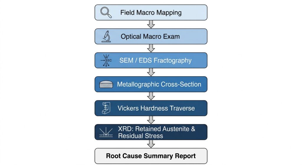
Fractography and Lab Workflow
Macroscopic Mapping to SEM Confirmation
A disciplined failure analysis starts at the widest view and zooms in. Macroscopic mapping of the fracture surface identifies:
- Origin region: Usually smooth, featureless (mirror zone), near a surface or subsurface defect.
- Propagation direction: Chevron marks and river lines converge toward the origin.
- Final separation zone: Rough, fibrous (if any ductile tearing present), or crystalline (fully brittle).
Once the origin is located to within ± 2 mm, scanning electron microscopy (SEM) at 200–2000× resolves the specific feature at initiation: a grinding crack, a carbide cluster, a quench crack, or a fretting pit. Energy-dispersive X-ray spectroscopy (EDS) on the fracture surface can identify oxidation on older cracks (pre-existing versus service-induced) and confirm inclusion chemistry. This is the same macro-to-SEM sequence Maxtor Metal’s QA team runs when a field failure sample arrives for root-cause analysis.
Metallography and Hardness Mapping Standards
Cross-sections through the fracture origin (and a second section remote from it for baseline comparison) are mounted, polished, and etched with Vilella’s or Marble’s reagent to reveal:
- Carbide morphology, size, and distribution.
- Prior austenite grain size per ASTM E112 (Standard Test Methods for Determining Average Grain Size).
- Decarburization depth per ASTM E1077.
- White-layer presence (unetched region at surface).
- Quench or grinding cracks.
Vickers microhardness traverses per ASTM E384 (Standard Test Method for Microindentation Hardness of Materials) from surface to core map hardness gradients. A blade with correct double-tempered microstructure should show no more than 3 HRC variation between surface and 10 mm depth. Deviations indicate thermal-process anomalies.
Retained Austenite Assessment and Acceptance Limits
RA quantification requires XRD or magnetic saturation measurement per ASTM E975 (Standard Practice for X-Ray Determination of Retained Austenite in Steel with Near Random Crystallographic Orientation). Metallographic estimation from nital-etched sections is semi-quantitative and subject to operator bias; it is acceptable for screening but not for specification compliance.
Industry-typical acceptance limits for shredder knife grades:
| Grade (Approximate) | Maximum RA (%) | Note |
|---|---|---|
| D2 / 1.2379 equivalent | ≤ 15% | Double-temper mandatory |
| D3 / 1.2080 equivalent | ≤ 12% | Higher carbon; lower RA tolerance |
| High-V modified | ≤ 10% | VC promotes RA stability; tighter limit |
Values exceeding these limits after final temper indicate either incorrect austenitizing temperature or insufficient temper cycle.
Pattern Recognition: A Quick Triage Before Lab Work
Field conversations rarely arrive as clean datasets. What we typically hear from customers is closer to “the edge chips, or it wears out faster than expected” — a symptom, not a root cause. Over 15 years of blade quality work, the same handful of symptom patterns keep resurfacing, and they point in different directions. The table below distils that experience into a starting hypothesis. Treat it as a triage filter, not a verdict — the lab steps in the next section are what confirm the cause.
| Customer-reported symptom | Usually points toward | First thing to check |
|---|---|---|
| Edge chips early in life, under normal feed, across several blades from one batch | Heat treatment — over-hardening or insufficient temper | Surface-to-core hardness traverse; temper cycle records |
| Hardness reads low, then cracks or grows dimensional change after weeks in service | Retained austenite transforming under stress | XRD retained austenite per ASTM E975 |
| Cracks appear shortly after hardening, before meaningful service | Quench cracking from excessive austenitizing temperature or gradients | Austenitizing records; grain size per ASTM E112 |
| Chipping localized to one edge zone, or repeating at the same band | Material segregation or carbide banding | Metallography for carbide networks; ESR vs. ingot route |
| Random large chips after a jam or reversing event | Mechanical overload from tramp material, not the blade | Feed-stream checks; clearance and alignment |
| Gradual, even material loss with no chipping | Expected abrasive wear, not a defect | Confirm edge geometry and material grade are appropriate |
The practical rule we apply: uniformly brittle behaviour across a batch points to heat treatment first; patchy, band-following, or blade-to-blade variation points to material inhomogeneity; isolated large chips after an incident point to overload. These three rarely arrive alone — contamination loading on a marginally quenched blade, for example, combines overload and a pre-existing defect.
This is exactly why we don’t diagnose from a phone description alone. A customer’s report tells us which lever to pull first; it does not tell us what the microstructure did. Only the sequence below closes that gap.
In breve: the symptom pattern tells you which lever to pull first—uniform batch brittleness points to heat treatment, patchy variation points to material inhomogeneity, isolated large chips point to overload—but only the lab sequence confirms it.
Supplier Qualification and Process Control

Pyrometry Discipline: AMS 2750, CQI-9, TUS/SAT
Thermal uniformity is the foundation of repeatable heat treatment. Without it, a correctly specified cycle can produce significant hardness and microstructure variation within a single blade or batch.
AMS 2750 (Nadcap-recognized pyrometry standard) defines instrumentation classes, calibration intervals, and temperature uniformity survey (TUS) requirements for heat-treatment equipment. A furnace processing shredder knife blades should meet minimum Class 4 uniformity (± 14°C) across the working zone, verified by TUS at defined intervals — typically annually and after major repairs.
CQI-9 (AIAG’s Heat Treat System Assessment) extends to automotive supply chain but is widely adopted in precision tooling as a process audit framework covering SAT (system accuracy tests), load thermocouples, and documentation requirements.
Non-compliance with these standards does not always manifest as an obvious defect. A furnace operating 20°C hot across one zone may consistently over-austenitize blades placed there, producing elevated RA in those pieces — creating field-failure clustering by position within the batch. Suppliers should provide TUS reports and SAT records with each heat-treat lot. Absence of these documents is a disqualifying finding.
Quench/Temper Control, RA Limits, NDT, and Traceability
Beyond pyrometry, controlled quench rate documentation — gas pressure versus time curve for vacuum-quench furnaces — allows retrospective verification when a field failure occurs. Deviations in the quench curve may correlate with RA exceedances.
Non-destructive testing requirements for finished shredder knives should minimally include:
- Magnetic particle inspection (MPI) per ASTM E1444 for surface and near-surface cracks.
- Ultrasonic testing (UT) per ASTM E114 for internal voids or segregation in thick sections (above 50 mm).
- Hardness spot-check with calibrated Rockwell C (HRC) tester on each blade, documented on the Material Test Certificate (MTC 3.1).
Full traceability — heat number, furnace lot, quench record, inspection result — enables precise recall when a field failure occurs and is the minimum expectation for a supply relationship where downtime consequences are severe.
Maxtor Metal documents heat-treatment controls — including furnace TUS compliance, quench curve records, and RA measurement results — as part of its standard MTC 3.1 package. The company operates an ISO 9001 certified quality management system, and supplier qualification is conducted by auditors holding Auditor capo ISO 9001 credentials. For facilities importing shredder blades from overseas suppliers, this one-stop traceability model eliminates the audit gap that often exists between the mill, the heat-treater, and the end user.
Audit Checklist and Contract Language for Risk Containment
A supplier qualification audit for shredder knife production should include, at minimum:
Process controls:
- AMS 2750 or equivalent pyrometry certification current (within 12 months)
- TUS records available for all heat-treat furnaces used for this product
- SAT records for all control and recording instruments
- Quench parameter log per batch
- Double-temper cycle documented and temperature-controlled (not time-estimated)
Material and microstructure:
- ESR melt route confirmed for cross-sections above 100 mm (or equivalent segregation control)
- RA measurement by XRD on sample-per-lot basis
- Hardness traverse (surface to 10 mm) on one blade per lot
- Decarburization check per ASTM E1077
NDT:
- MPI per ASTM E1444, 100% of blades
- UT for sections above 50 mm, per ASTM E114
Documentazione:
- MTC 3.1 with heat number, furnace lot, and all above test results
- Grinding process record (wheel speed, feed rate, coolant flow rate)
- XRD residual stress measurement on edge surfaces (contract-specified)
Contract language should specify acceptance limits — for example, “RA ≤ 15% by XRD per ASTM E975; hardness 60–63 HRC; surface residual stress ≤ +50 MPa tensile” — and define the disposition process for non-conforming lots, including hold-and-test protocols and field-failure data-sharing obligations.
In breve: AMS 2750 pyrometry certification, TUS/SAT records, lot-level RA by XRD, and full MTC 3.1 traceability aren’t optional paperwork—absent them, a furnace running 20°C hot can silently over-austenitize an entire batch.
Implementation and KPIs
Hardness Windows and Alloy Selection by Duty
Not all shredding duties are equal. Light-gauge ferrous scrap tolerates 62–64 HRC with minimal toughness sacrifice; heavy demolition scrap or mixed MSW streams with unpredictable contamination favor 58–61 HRC to move K Ic further from the service stress envelope. A structured alloy-selection matrix based on feed stream characterization prevents the common error of defaulting to maximum hardness regardless of application.
| Feed Stream | Recommended HRC | Alloy Notes |
|---|---|---|
| Light-gauge steel scrap (below 6 mm) | 62–64 | D2 / Cr12MoV equivalent |
| Heavy structural scrap (above 25 mm) | 59–62 | D3 or high-V modified |
| Mixed MSW / contaminated streams | 57–60 | H13 or semi-tough grade |
| Automotive shredding (mixed alloy) | 60–62 | ESR D2 preferred |
For the full cost-per-ton framework behind this hardness-versus-toughness trade-off—including a published failure case where fracture originated at geometry, not hardness—see Scrap Tire & ELV Size Reduction: Balancing Knife Hardness vs. Toughness (D2 vs DC53) to Cut Cost Per Ton.
Incoming Inspection and Run-at-Rate Trials
Purchasing specification acceptance should not rely on MTC review alone. Incoming inspection protocol:
- Hardness check — 3 points per blade, per lot (reject if any point is ± 2 HRC outside nominal).
- Dimensional check — bore diameter, keyway profile, edge chamfer (per drawing).
- Visual/MPI on first article of each new supplier lot.
- Microstructure review (metallographic section) on first-article qualification and annually thereafter.
Run-at-rate trials — operating a new blade lot through one full shift under normal feed conditions before full deployment — provide the most operationally relevant performance signal and can detect sub-threshold defects that lab testing misses.
For the complete incoming-inspection workflow this protocol summarizes—spec control, CMM sampling plans, and MTR documentation review—see Approvvigionamento di lame per trituratori aftermarket: Controllo specifiche, piano CMM, convalida MTR e verifica dell'accoppiamento funzionale..
KPIs: MTBF, Uptime, Particle-Size Stability, Energy/Ton
Blade performance tracking requires metrics that isolate blade contribution from feed-stream variation:
- MTBF (Mean Time Between Failures): Track by blade lot number to detect batch-level quality variation.
- Line uptime %: Catastrophic failures per 1,000 operating hours as a rate, not just absolute count.
- Particle-size stability: Shredder output gradation tightening indicates edge dulling; sudden coarsening can signal blade chipping that precedes fracture.
- Energy/ton: Specific energy consumption rises before catastrophic failure as blade geometry degrades. A sustained rise of 8% or more above baseline is a trigger for scheduled inspection.
Tracking these KPIs by blade supplier and heat-treat lot transforms anecdotal failure reports into statistically defensible supplier scorecards.
In breve: hardness selection should follow feed-stream severity, not default to maximum HRC—and MTBF by lot number, energy/ton trends, and particle-size monitoring are what convert anecdotal failures into supplier accountability.
Domande Frequenti
What causes shredder blades to shatter instead of just wearing out?
Shattering — brittle fracture — occurs when a crack propagates faster than the steel can deform plastically. In high-hardness tool steels, the fracture toughness (K Ic) is inherently low. Pre-existing defects (quench cracks, grinding cracks, carbide clusters, retained austenite pockets) reduce the effective toughness further. When a contamination event — tramp steel, concrete, refractory — delivers a peak stress above K Ic at a defect site, the blade fails catastrophically rather than wearing gradually.
How much retained austenite is acceptable in a shredder knife?
For D2-equivalent grades, the widely applied upper limit is 15% RA by XRD measurement per ASTM E975. Higher-carbon D3-equivalent grades should be held to 12% or below. RA above these levels is metastable: stress-induced martensitic transformation during service introduces local volume expansion of approximately 4% that nucleates cracks. Double-temper cycles at 500–550°C are the standard process control to reduce RA after quenching.
What is the correct heat-treatment process to prevent quench cracking in shredder blades?
The critical controls are: (a) austenitize within the specified temperature window (typically 980–1050°C for D2-type; verify per material specification); (b) complete first temper within 2 hours of quench to relieve martensite transformation stresses before they accumulate; (c) apply a double-temper cycle at the grade’s specified temperature; (d) use vacuum furnace quenching with gas pressure control to minimize thermal gradients. Furnace uniformity should comply with AMS 2750 Class 4 or better (± 14°C across the working zone).
Can grinding damage cause a shredder blade to shatter in service?
Yes. Aggressive grinding introduces tensile residual stress — potentially exceeding 400 MPa — and can produce un-tempered martensite (white layer) at the surface. Both conditions reduce the effective fracture initiation threshold. XRD measurement of residual stress on finished edge surfaces, specified as no more than +50 MPa tensile, is the only reliable verification method. Burn marks visible on the surface are a lagging indicator; damage may exist without visible discoloration.
How do I diagnose what caused a shredder blade to break in the field?
Begin with macroscopic fracture mapping to locate the origin region (smooth mirror zone). Photograph and preserve fracture surfaces — do not clean them. Submit for SEM/EDS to identify the initiation feature (crack, inclusion, carbide cluster, fretting pit). Follow with metallographic cross-section through the origin for microstructure and hardness data. XRD on a retained section provides RA content and residual stress. This sequence, from field observation to lab confirmation, typically resolves root cause within 5–7 working days.
What NDT methods detect internal defects in shredder blades before installation?
Magnetic particle inspection (MPI) per ASTM E1444 detects surface and near-surface cracks. Ultrasonic testing (UT) per ASTM E114 is required for cross-sections exceeding 50 mm to detect internal voids, laps, or gross segregation. Both should be specified in purchasing contracts and documented on the MTC 3.1. Hardness spot-checks per blade provide a final screening step for heat-treat consistency.
How do I choose between D2 and tougher grades for my shredding application?
Match hardness to feed-stream impact severity. D2-equivalent at 62–64 HRC is appropriate for light-gauge ferrous scrap with predictable feed. Heavy structural scrap, demolition material, or streams with unpredictable contamination expose blades to overload events that exceed the toughness limit of fully hard D2. In those cases, stepping down to 58–61 HRC with a modified chemistry (higher V, slightly lower C) significantly reduces shattering risk at modest wear-life cost. Feed-stream characterization — maximum piece size, estimated contamination rate — should drive alloy selection, not default practice.
What KPIs should I track to detect blade degradation before catastrophic failure?
Track specific energy consumption (kWh/ton) — a sustained rise of 8% or more above baseline signals geometry degradation. Monitor output particle-size distribution; coarsening indicates edge loss. Record MTBF by blade lot number to detect batch-level quality variation from suppliers. Combine these with visual edge inspection at every scheduled maintenance window. Together, these metrics provide early warning of degradation trajectories that precede brittle fracture events.
Conclusione
Catastrophic blade shattering is a convergent failure — brittle fracture mechanics amplified by pre-existing microstructural defects, stress concentrators from geometry and fit, and the stochastic contamination events that every shredder line encounters. No single intervention eliminates the risk; the combination of controlled metallurgy, disciplined thermal processing, systematic fractographic diagnosis, and rigorous incoming inspection does.
The takeaways are direct:
- Metallurgy sets the ceiling. ESR melt route, correct austenitizing, double-temper, RA at or below 15% by XRD, and compressive residual stress at the ground edge are non-negotiable for shock-loaded shredder environments.
- Fractography identifies the root. Without SEM confirmation of the fracture origin, corrective actions are guesses. Build the lab workflow into your failure-response protocol.
- Supplier controls close the gap. AMS 2750 pyrometry, lot-level RA measurement, MPI, UT, and full MTC 3.1 traceability are the contractual floor, not optional extras.
- KPIs make improvement visible. MTBF by lot number, energy/ton trends, and particle-size monitoring convert operational experience into supplier accountability.
For operations evaluating their shredder tooling supply chain, Maxtor Metal’s shredder blades and shredding knives are produced under documented heat-treatment controls with full material traceability — a practical starting point for reducing catastrophic failure exposure without rebuilding your supplier qualification system from scratch.
Continuous improvement requires requalification after every significant feed-stream change, every furnace overhaul at a supplier, and every field failure — treating each event not as an anomaly to close out but as a measurement that the control system needs.
Technical references: ASTM A681 (alloy tool steel); DIN EN ISO 4957 (tool steels); ASTM E975 (XRD retained austenite); ASTM E384 (Vickers microhardness); ASTM E1444 (magnetic particle inspection); ASTM E114 (ultrasonic testing); ASTM E1077 (decarburization); AMS 2750 (pyrometry); AIAG CQI-9 (heat treat system assessment); ASM Handbook Vol. 4A (Steel Heat Treating Fundamentals and Processes).
Informazioni sull'autore
Jesse Xu — Senior Quality Engineer, QA, Maxtor Metal
Jesse Xu is a Senior Quality Engineer at Maxtor Metal, where he leads quality assurance and failure analysis for precision-ground industrial blades. With 15 years of experience in tool steel quality control, he specializes in root-cause failure analysis — including determining whether edge chipping and premature wear originate from heat-treatment process deviations or from material segregation and carbide banding. This diagnostic work connects directly to the fracture-mechanics and process-control principles covered in this article.
His professional credentials include:
- ASQ Certified Quality Engineer (CQE)
- Auditor capo ISO 9001
- ANT Livello II (Nondestructive Testing)
Jesse applies this expertise to incoming material verification, heat-treatment process auditing, and the retrofit of supplier acceptance criteria for shredder knife production — the same controls discussed in the supplier qualification and incoming inspection sections above.
This article was reviewed for technical accuracy by Maxtor Metal’s QA team. Maxtor Metal is a manufacturer and supplier of custom, precision-ground industrial blades operating an ISO 9001 certified quality management system; the standards and acceptance limits referenced are drawn from the published ASTM, AMS, ASM, and AIAG documents listed above.

 English
 Spanish
 Italian
 French
 Portuguese
 Russian
 German
 Arabic
 Hindi
 Vietnamese
 Indonesian
 Japanese
 Korean