

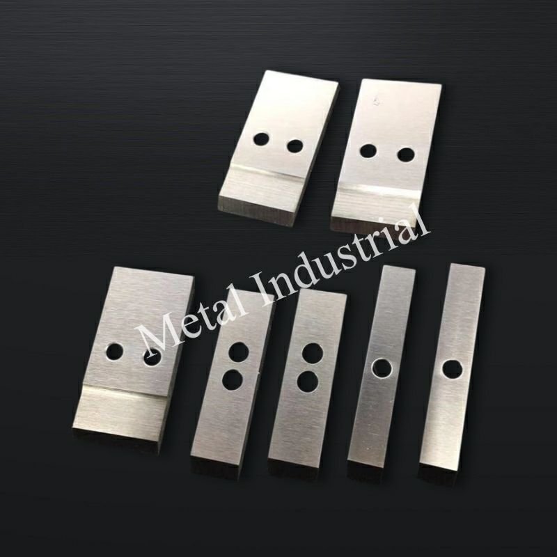
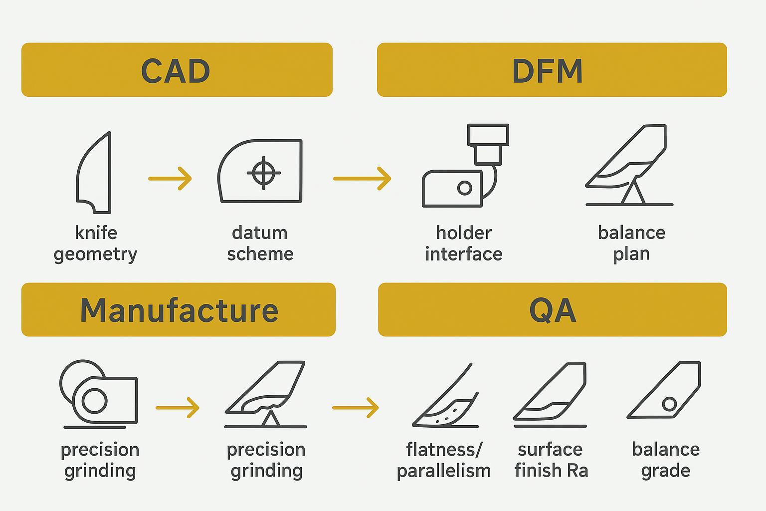
Custom pelletizer knives for underwater (water-ring/die-face) cutting don’t become production-ready by chance. They get there through a disciplined chain: CAD intent → DFM reality → controlled manufacturing → auditable QA → run-in validation on your line. In this guide, you’ll see how geometry, materials, precision grinding, and documentation come together to shorten run-in and extend service life—two levers that directly raise uptime and cut unplanned stops.
You’ll learn:
- What to capture in CAD so the knife shears cleanly at the die face.
- How to translate drawings into DFM that preserves edge integrity and fit-up.
- Which materials, joining methods, and coatings make sense for recycled and filled PE/PP.
- The metrology that matters: flatness, parallelism, edge land width, surface finish, and balance.
- What belongs in the QA packet and how to prove readiness at startup.
This helps plant, production, maintenance, and purchasing teams who need predictable pellets, fewer tails and fines, and knives that settle quickly and stay in spec longer.
主なポイント
- Prioritize uptime: design and verify knives to reduce run-in time and extend intervals between changeovers.
- Tie specs to measurement: define flatness, parallelism, edge land width, surface finish (Ra), and balance with traceable methods.
- Stabilize shear at the die face: maintain uniform contact geometry and controlled spring/force so knife-to-die behavior is consistent.
- Choose materials and coatings by duty: match base steel or carbide and topcoats to recycled/filled PE/PP heat and abrasion profile.
- Require a complete QA packet: material certs, hardness, coating checks, dimensional/balance reports, plus a run-in checklist.
- Validate on your line: use acceptance criteria (tails, fines, vibration) to confirm production readiness before full-scale.
CAD-to-DFM fundamentals for underwater cutting
Geometry essentials that stabilize shear at the die face
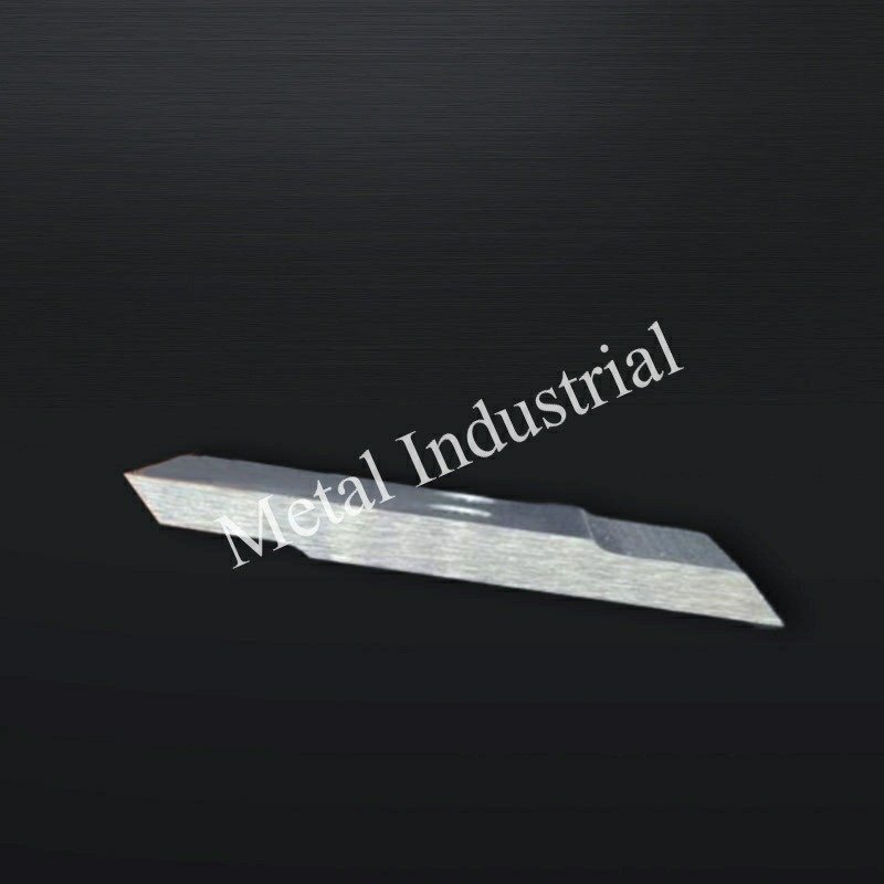
Clean, repeatable shearing at the die face depends on consistent geometry across the entire knife set. In CAD, define a clear datum scheme so grinding references aren’t ambiguous later. Capture the working edge geometry (macro rake/clearance and the micro “edge land”) as separate, inspectable features. Keep the cutting edge straightness and planarity correlated to a primary datum surface so knife-to-die contact is uniform when the cutter is loaded.
Because public, OEM-specific numeric targets vary, treat numeric examples as typical and focus on method. Specify flatness and parallelism as GD&T controls (ASME Y14.5 / ISO 1101 families) tied to functional datums. That lets you verify that the knife sits and sweeps evenly, minimizing local high spots that cause intermittent contact, heat, and premature wear. Surface texture (ASME B46.1 / ISO 21920 series) at the edge land should be low enough to avoid micro-tearing and fines.
Functionally, the goal is a minimal, controlled knife-to-die interface that stays stable as thermal conditions change. Systems that apply a constant spring or compliant force at the cutter help keep contact behavior consistent as components grow or shrink with temperature, which supports steadier pellets and fewer excursions, as OEM documents on underwater pelletizing systems describe from a system perspective (see MAAG’s tempered water and underwater pelletizing briefs for context).
Holder interface, balance, and retrofit fit-up
Your CAD must match the holder’s locating and clamping scheme—hole pattern, counterbore depths, reliefs, and any pins or steps—so stack-up doesn’t shift the edge where you don’t intend it. Model and tolerance the assembled center of mass and plan for dynamic balancing of the rotating cutter assembly. Reference balancing practice using ISO 21940-11 grade concepts (e.g., G2.5–G6.3 class targets by speed/rigidity) and specify verification in one or two planes as appropriate.
For retrofit into Gala/MAAG ecosystems, capture critical dimensions that preserve OEM offsets and sweep envelope. A small mislocation at the mounting face can become a large edge-position error at radius. Guard against tolerance stack-ups with clear datums and perpendicularity controls.
Setup forces and cooling water factors to control tails
Knife-to-die force that’s steady and within the machine’s intended range reduces chatter, edge chipping, and tail formation. Many underwater systems use mechanisms that keep a constant force on the cutter so operators aren’t constantly chasing contact. Cooling water flow and temperature also influence tailing and fines by affecting pellet solidification and transport. MAAG’s documents on tempered water systems explain how closed-loop flow and moderated temperatures stabilize the process, which indirectly supports cleaner cuts and fewer defects.
OEM documentation connects these parameters to outcomes: closed-loop water circuits that hold a moderated setpoint and ensure adequate, uniform flow stabilize pellet solidification and transport, which reduces tailing and fines. This control logic is outlined in MAAG’s Tempered Water Systems brief and reinforced in ECON’s EWT tempered water system overview, which describes temperature setpoint regulation and flow distribution to keep cutting conditions steady at the die face.
Materials, heat treatment, joining and coatings
Base steels vs. carbide edges for recycled and filled PE/PP
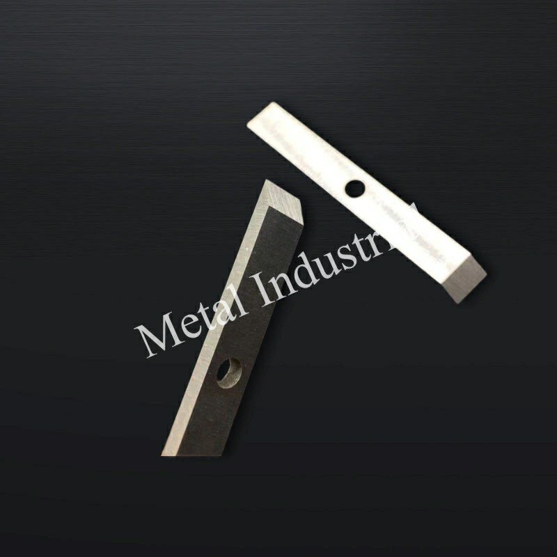
Match the edge material to the duty. D2 is a common baseline for general-duty thermoplastics. For hotter runs or higher abrasion, high-speed steels (e.g., M2) or PM high-vanadium tool steels offer improved hot hardness and wear resistance. In streams with glass/mineral fillers or contaminants typical of recycled PE/PP, carbide-tipped or full-carbide edge solutions preserve sharpness longer and help extend intervals between changeovers. OEM and reputable supplier literature on underwater pelletizing tools highlights carbide’s role where abrasion dominates.
Vacuum heat treat, brazing, and HIP for bond strength
Vacuum heat treatment keeps surfaces clean and reduces oxidation, which improves dimensional control and edge quality. When joining carbide to a steel body, use qualified brazing processes (in vacuum or controlled atmosphere) with appropriate filler selection and joint design, and consider hot isostatic pressing (HIP) to densify interfaces or PM substrates and improve bond integrity. Third-party resources describing vacuum brazing and HIP provide the process rationale; your QA should reflect joint cleanliness, filler specification, and post-braze inspection.
Coating and non-stick topcoat selection by duty and heat
Hard PVD/CVD coatings such as TiN or DLC can raise surface hardness and lower friction where abrasive or high-temperature service would otherwise accelerate wear. In sticky recycled streams, a non-stick topcoat (e.g., PTFE-type) on non-critical faces can reduce adhesion and ease cleaning. Choose coatings that survive your thermal envelope and won’t spall at the edge during run-in.
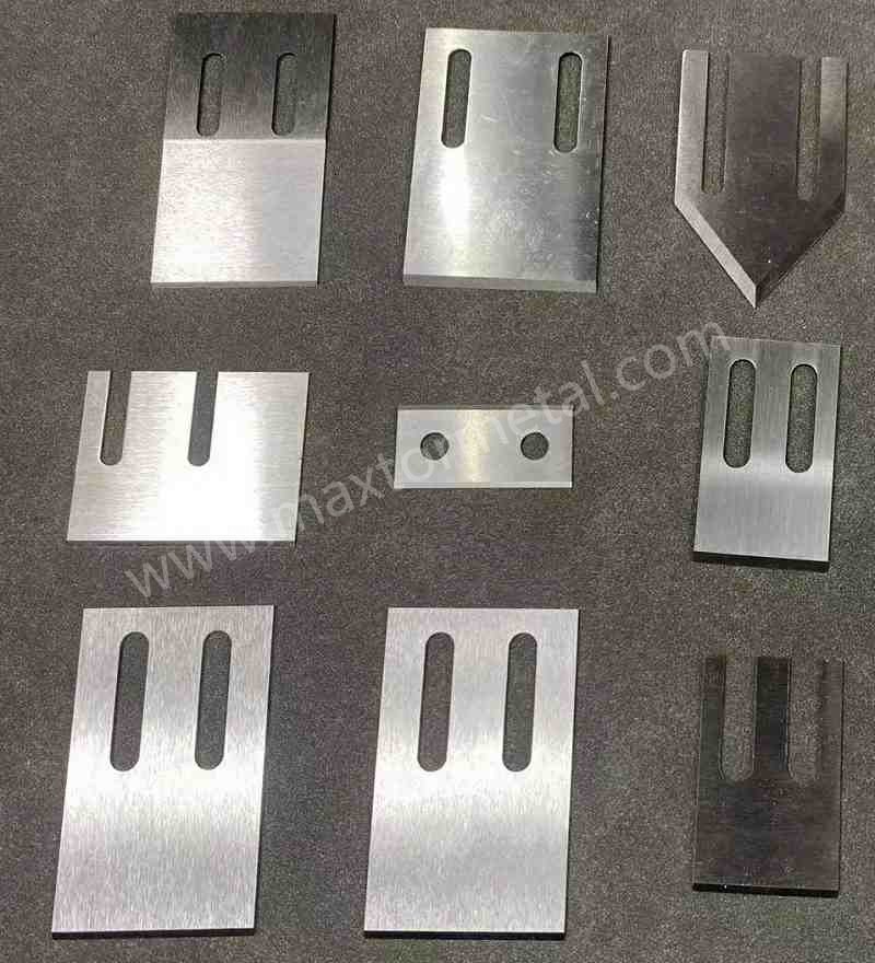
A neutral example of a QA-backed custom-fit workflow: マックストールメタル supports manufacturing to customer drawings or samples with material selection options (e.g., D2/M2/PM steels, carbide-tipped designs), vacuum-brazed joints via partners, and optional hard and non-stick coatings, delivered with inspection records for flatness/parallelism, surface finish, and hardness. Disclosure: MAXTOR METAL is our product. For background on tolerances and QA practices, see MAXTOR’s resources on an 工業用ブレード公差ガイド そして quality and inspection overview.
Precision grinding and dimensional control
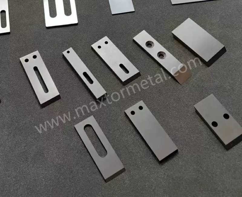
Flatness and parallelism targets for consistent contact
Flatness and parallelism keep the knife’s working faces seated so the edge sweeps the die uniformly. Specify flatness as a form control relative to a primary datum surface and parallelism to align secondary faces. Verification can use a granite plate and dial indicator mapping, bridge/arm CMMs (validated per ISO 10360 families), or optical systems. Because public, pelletizer-specific numbers are scarce, many plants use “typical” ranges informed by function and instrument resolution; the important part is to record the method, instrument, and uncertainty on the inspection report. For reference on flatness concepts and measurement methods, see metrology primers from instrument makers.
Edge land width and surface finish for low fines
The edge land is the micro-geometry that stabilizes the cut. Too wide and you push and heat; too narrow and you chip and shed fines. Treat land width and surface texture as inspectable features. Optical or contact profilometry can quantify land width and Ra. Grinding should deliver a crisp land with a low-Ra finish that reduces micro-tearing without sacrificing bite. Knowledge pages from cutting-tool vendors on surface generation and finishing parameters provide transferable principles for achieving low Ra at edges.
Third-party evidence links edge micro-geometry to burrs/fines via the same ploughing-versus-shearing mechanism discussed here. In a simulation-plus-experiment study, larger tool tip radius increased outlet burrs because more material was pushed (ploughed) instead of cleanly sheared, as shown in MDPI’s 2023 Micromachines burr formation study. Likewise, when the undeformed chip thickness approaches the edge radius, ploughing dominates and burrs and roughness rise, according to Copernicusの2021年『Mechanical Sciences』誌におけるマイクロエンドミル加工研究. 。これらのテストはマイクロスケールの金属を対象としていますが、変形力学の挙動はダイス面におけるポリマーのせん断加工にも適用できます。幅が狭くエッジの立ったランド部(および低Ra表面仕上げ)はせん断優位の状態を維持して微粉(ファイン)の発生を抑制する一方、過度に広いランドや丸みを帯びたエッジはすき込み(プラウイング)現象へとシフトし、微粉の発生を増加させます。このメカニズムを支配するマイクロジオメトリ(微細形状)がロット間で管理されるよう、検査計画にランド幅とRaを明記してください。.
データム方式およびGala/MAAG互換公差
ナイフがホルダーおよびハブに組み合わされる状態を反映したデータムを設定します。位置度および直角度を使用して、ナイフの回転スイープ面を決定する穴パターンと面を管理します。ISO 21940-11の概念に基づく適切な等級への検証を行い、回転カッターアセンブリのバランシング要件(回転速度および修正面の数を明記)を含めてください。Gala/MAAGシステムへのレトロフィット(換装)の場合は、出荷前に製造部門および受入検査で嵌合を確認できるよう、図面に重要なインターフェース寸法とオフセットを含めます。.
QA documentation and run-in validation
材料証明書、硬度、およびコーティングの検証
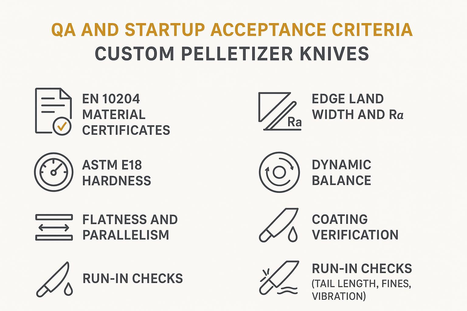
品質保証(QA)文書には、チャージ番号(ヒート)および化学成分を示す材料証明書(金属製品の場合は通常EN 1024 3.1)、ならびにNISTトレーサブルなテストブロックを使用しASTM E18規格に準拠して測定・報告された硬度測定結果を含める必要があります。コーティングを施す場合は、種類、膜厚範囲、密着性検証方法をドキュメント化してください。ろう付け部がある場合は、ろう材の仕様および実施した外観・非破壊検査(NDT)の内容を明記します。.
トレーサビリティのある測定機器による寸法検査レポート
寸法検査レポートには、平面度、平行度、エッジランド幅、穴位置など、管理対象となる各形状特性について、測定方法、使用機器、校正状態を記載する必要があります。三次元測定機(CMM)を使用する場合は、装置の検証基準(ISO 10360シリーズ)、プローブタイプ、測定環境条件を含めてください。表面粗さについては、Ra測定パラメーターを記録します。リンク密度は低く抑えつつ、第三者の試験機関が測定を再現するのに十分な詳細情報をレポートに含めるようにします。.
導入を促進し、ドキュメントを即座に活用できるようにするために、再利用可能な資産(上記特性に対応するバージョン管理されたQA検査チェックリストおよび寸法検査レポートテンプレート(CSV/PDF))を同封してください。当社の社内用テンプレートにアクセスし、硬度(ASTM E18)、表面粗さ(Ra)、CMMのトレーサビリティをどのように検証しているかについて、当社の 品質および検査の概要.
立ち上げ時の慣らし運転(ランイン)チェックリストおよび合格基準
本格生産に入る前に、構造化された慣らし運転を実施してラインの準備状態を検証します。装置の手順に従い、ナイフとダイスの接触状態、カッター加圧機構の機能、および水システムの設定値(流量と温度)を確認します。短時間の安定化の後、ペレットをサンプリングしてテール長さの分布と微粉率を特定し、バランスと適正嵌合の指標としてカッターハウジングの振動を記録します。製品や顧客の要求に適合する合格基準(例:規定のppmまたはパーセンテージ範囲内でのテールの発生率、しきい値以下の微粉率など)を定義し、その結果を立ち上げレポートに記録してください。.
Failure modes and preventive SOPs
ダイプレートの溝摩耗と加速摩耗の抑制
局所的な高加圧による継続的なナイフの接触は、ダイプレートに溝状の摩耗を生じさせ、カット品質の低下、発熱、およびテールの原因となります。接触形状の均一化を図り、カッター加圧機構を検証し、確認された摩耗状況に基づくスケジュールに従ってダイス面を再研磨することで摩耗を緩和します。水中ペレタイズシステムに関するOEMの技術ドキュメントでも、ダイス面の保護対策やコーティングの採用が推奨されています。必要に応じてこれらを活用し、計画停止時に溝の深さを監視してください。.
エッジの欠け、振動、および累積公差の管理
刃先のチッピング(欠け)は、通常、不安定な接触パターン、あるいはアンバランスや位置ズレによる振動を示しています。厳格なデータム運用により累積公差を管理し、回転アセンブリの動的バランスを検証し、穴位置および取り付け面を検査します。ハウジングでの振動や異音の上昇が見られる場合は、それを先行指標として捉え、刃先が劣化する前に修正を行ってください。.
粘着性のあるリサイクル原料における樹脂付着の抑止
粘着性の高いリサイクル原料の場合は、適切な非粘着性トップコーティングを施工して重要でないナイフ表面への付着を防止し、水温および水量を装置の推奨範囲内に維持します。エッジランドに丸みを付けることなく付着物を除去できる清掃SOP(標準作業手順書)を策定し、再起動前に迅速な光学検査で確認します。.
マイクロケース(匿名化された現場試験):Gala互換の水中ペレタイザーを運用する北米のプラスチックリサイクル企業が、公差および材質のアップグレード(平面度・平行度管理の厳格化、超硬チップ刃、検証済みのなじみ運転SOP)を検証しました。ベースライン:なじみ運転 6〜8 時間、交換周期 72 時間ごと、テイル/微粉発生量 重量比約 1.8%、ハウジング振動ピーク約 4.5 mm/s。導入後(6週間の試験):なじみ運転は 1〜2 時間に短縮、交換周期は 160 時間に延長、テイル/微粉発生量は約 0.5% に低減し、ピーク振動は約 2.0 mm/s に減少しました。顧客の要望により匿名にて報告していますが、提示データはサプライヤーが確認済みの生産ログに基づいています。.
結論
カスタムペレタイザーナイフの仕様決定と検証は、勘に頼るものではありません。CAD上の設計意図を製造可能な刃先に落とし込み、精密研削によって平面度・平行度およびマイクロ幾何形状を維持し、トレーサビリティのあるQAで立証した上で、実際のラインでスムーズに動作することを確認するプロセスです。これらのステップを統合することで、なじみ運転時間が短縮され、交換周期が延長されるため、計画外停止を削減しながら稼働率を向上させることができます。.
次のステップ:図面上でデータム方式と測定方法を確定し、サプライヤーに求めるQA文書パッケージを標準化すること。使用しているGala/MAAGエコシステムに対してレトロフィットに不可欠な寸法を確認し、明確な合格基準を設けたスタートアップチェックリストを使用して生産準備状態を検証してください。刃物製造における公差や検査基準の背景についての詳細は、上述の社内リソースおよび水中ペレタイズ/温水システムに関するOEM・システム文書を参照してください。.
参考文献および詳細情報(抜粋・概要):
- 水中ペレタイズシステムおよび温水システムに関するOEMシステムの仕様情報は、MAAGの概要資料にて確認できます: 水中ペレタイズシステム そして 温水システム.
- 幾何公差および表面性状の規格体系については、以下を参照してください: ASMEポータルのY14.5およびB46.1シリーズ およびISOインデックスの 製品の幾何特性仕様(GPS).
- 平面度および粗さに関する計測技術の解説: キーエンスの平面度解説; キーエンスの光学式粗さ測定の概要.
- バランシング作業および等級の概要: Schenck HMバランシングマシン および以下を経由したISO 21940-11等級の背景情報: ISOインデックス.
- 硬さおよび材料証明書に関するQA規格基準: ASTM E18 ロックウェル硬さ および以下を経由したEN 10204証明書タイプ: BSIの概要.

 English
 Spanish
 Italian
 French
 Portuguese
 Russian
 German
 Arabic
 Hindi
 Vietnamese
 Indonesian
 Japanese
 Korean