

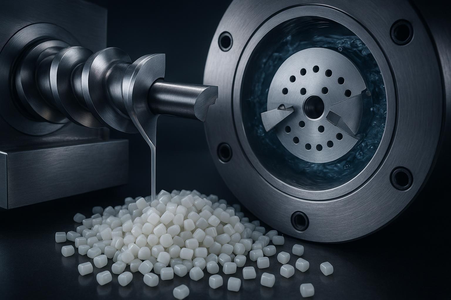
칼날 선택은 펠렛의 균일성, 가동 시간 및 총비용을 개선하기 위해 취할 수 있는 가장 신속한 조치 중 하나입니다. 스트랜드 펠레타이징에서 칼날의 핵심은 헬리컬 시저(helical scissor) 기하학적 구조, 로터와 베드 나이프(bed knife) 간의 간격, 그리고 마모로 인해 이 간격이 얼마나 빨리 벌어지는가에 있습니다. 수중 펠레타이징(다이 페이스/워터 링)에서는 제어된 나이프 접촉 압력, 시동 시의 열 균형, 그리고 강력한 공정수 흐름을 통해 깨끗하고 안정적인 절단을 유지하는 것이 핵심입니다.
본 가이드에서는 마스터배치 펠레타이저 칼날의 재질, 기하학적 구조, 간격/압력 범위 및 코팅을 비교합니다. 당사는 두 가지 실제 생산 현장의 애로사항인 수중 시동 안정성 및 나이프 압력 제어(꼬리 발생/미분), 그리고 스트랜드 간격 드리프트 및 교체 주기에 초점을 맞추는 동시에, 신속한 의사결정을 돕는 실용적인 선택 매트릭스를 제공합니다.
핵심 요약
- 수중 펠레타이징: 제어된 접촉 압력으로 시작한 다음 시스템이 안정화됨에 따라 압력을 낮춥니다. ECON 및 MAAG/Gala 등의 OEM 가이드와 Xinda 및 Plastics Technology의 애플리케이션 노트를 준수하여, 시동 시 다이 온도를 따뜻하게 유지하고 충분한 수량을 확보하여 꼬리 발생 및 미분 급증을 방지하십시오.
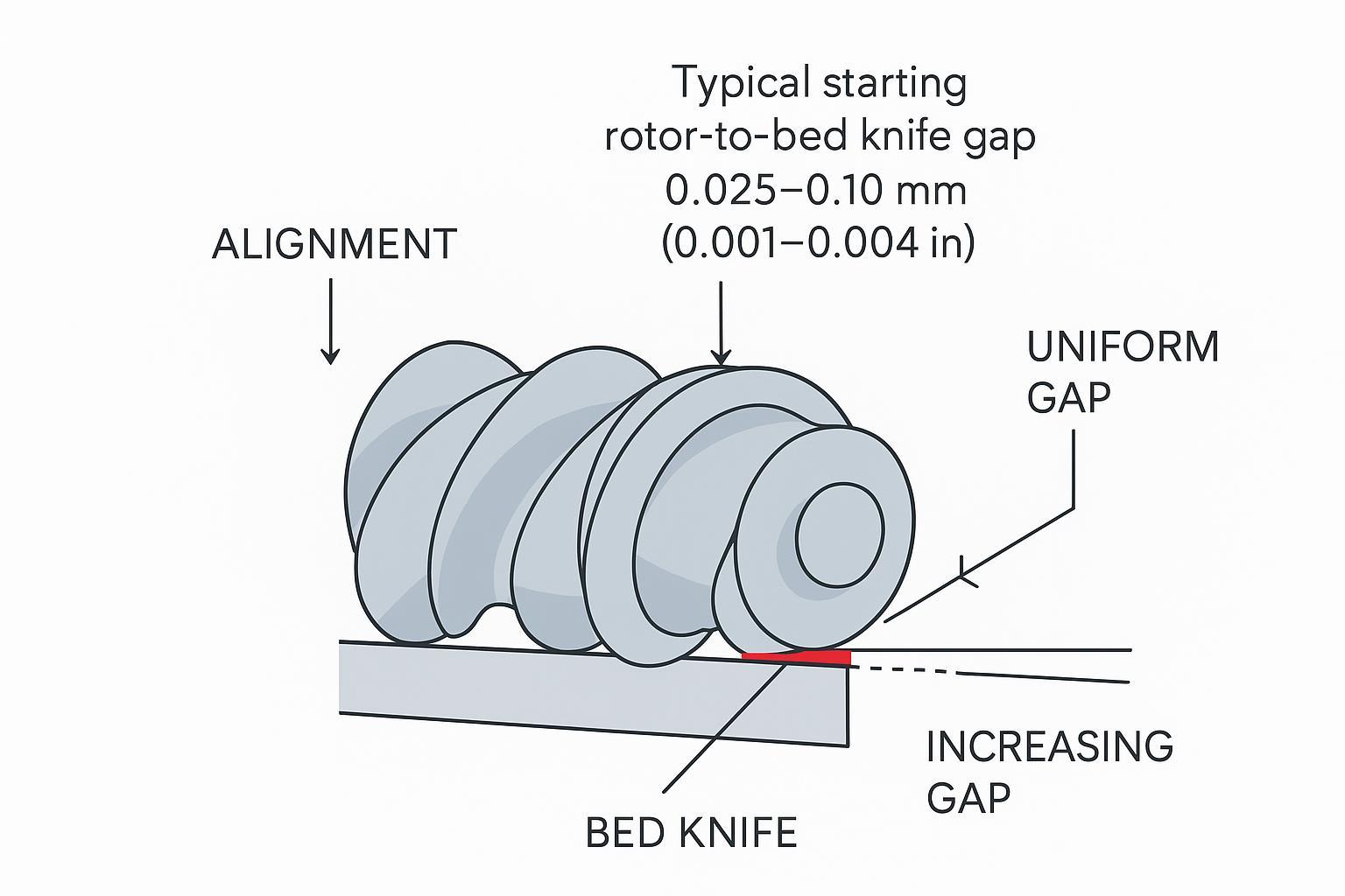
- 스트랜드 펠레타이징: 직선형 베드 나이프를 상대로 균일하고 조밀한 초기 간격 범위(0.025–0.10 mm 수준)를 가진 날카로운 헬리컬 로터가 절단하여 미분을 줄입니다. 마모가 누적됨에 따라 간격을 재조정하고 정렬을 다시 맞추십시오.
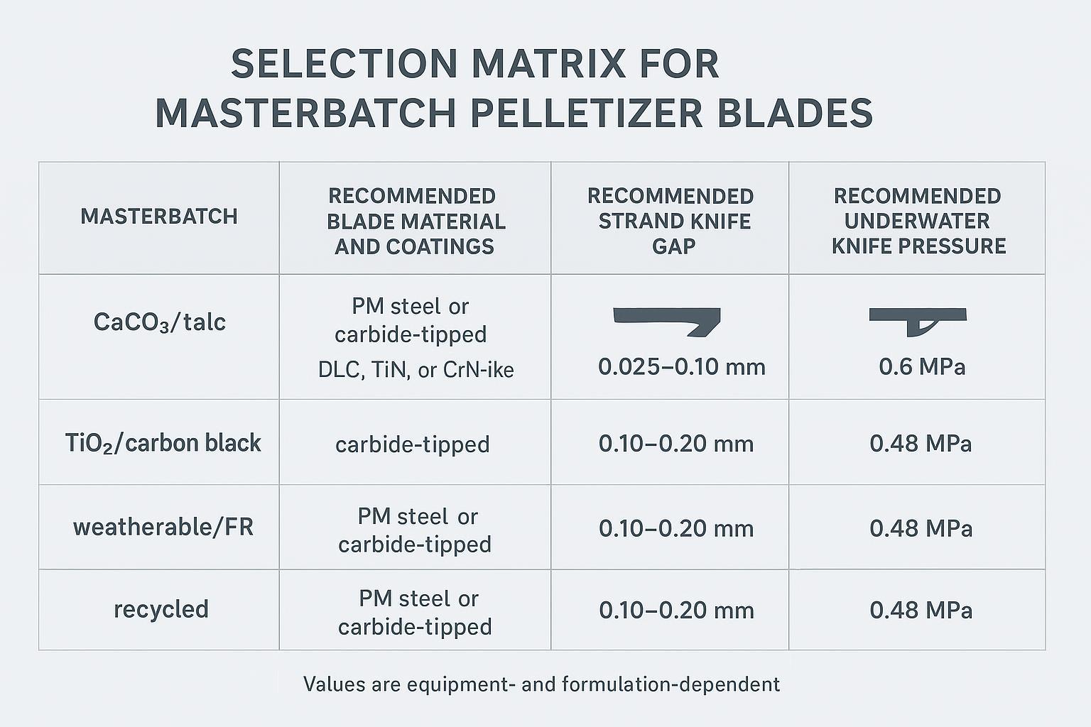
- 마모성이 높은 마스터배치(CaCO3/활석)에는 인성이 높고 내마모성이 우수한 기재(PM강, 카바이드 팁)와 저마찰 코팅이 유리하며, TiO2/카본 블랙에는 안티 픽업(anti-pickup) 코팅이 적용된 강인한 기재가 효과적입니다.
- 여기에 제시된 수치는 항상 “일반적인 초기 범위”로 간주하십시오. 귀사의 배합 및 처리량에 대해 OEM 매뉴얼을 확인하고 테스트를 통해 검증하십시오.
스트랜드 펠레타이징의 필수 요소
마모성 원료용 로터/베드 재질
고함량 CaCO3 또는 활석 마스터배치의 경우, 마모로 인해 절단 날이 빠르게 마모되어 둥글게 변합니다. 실용적인 초기 선택지로는 기본형인 D2/SKD11, 열과 마모가 심한 환경에 적합한 M2 HSS 또는 PM 등급 공구강(바나듐 함량이 높은 강), 그리고 극단적인 경우 카바이드 팁 베드 나이프가 있습니다. 일반적인 나이프 바디의 목표 경도는 대략 57–62 HRC 범위(등급에 따라 다름)로 설정되어, 날이 너무 부서지기 쉬워 미세 치핑(micro-chipping)이 발생하고 이로 인해 미분이 다량 발생하는 현상 없이 수명을 연장합니다. 공급업체 요약 및 OEM 페이지에서 이러한 범위와 코팅 옵션을 설명하고 있으며, 예를 들어 Sollex의 펠렛 칼날 개요(일반적으로 55–62 HRC) 및 MAAG의 나이프 및 홀더 문서가 있습니다. 자세한 내용은 Sollex의 펠렛 칼날 카테고리 페이지와 MAAG의 나이프 홀더 및 나이프 페이지의 논의를 참조하십시오.
- Sollex의 펠렛 칼날 개요(일반적인 경도 범위 55–62 HRC)에 따르면, 더 단단한 기재에 TiN/CrN/DLC 계열과 같은 PVD 코팅을 결합하면 원료 부착(pickup)을 줄이면서 서비스 수명을 연장할 수 있습니다. 출처: Sollex 펠렛 칼날 개요.
- MAAG의 스트랜드 펠레타이저 자료에서는 마모성 필러를 고속으로 가공할 때 필수적인 정밀 정렬과 내구성 있는 절단 부품의 중요성을 강조합니다. 출처: MAAG 스트랜드 펠레타이저 브로셔.
헬리컬 시저 기하학적 구조 및 간격
수중 펠레타이징: 제어된 접촉 압력으로 시작한 다음 시스템이 안정화됨에 따라 압력을 낮춥니다. 시동 시 다이 온도를 따뜻하게 유지하고 충분한 수량을 확보하여 꼬리 발생 및 미분 급증을 방지하십시오 (Plastics Technology — “Mitigating and Troubleshooting Underwater Pelletizing Issues”, 2020; MAAG — PURO 온수 시스템 브로셔, 2016; Xinda 애플리케이션 노트, 2026년 확인).
- 시저 작용(scissor action) 및 전단 공정의 영향에 대한 배경 지식은 압출기와 펠레타이저 사이에서 일어나는 일에 관한 Plastics Technology 기사를 참조하십시오.
- 실용적인 트러블슈팅 팁(예: 간격 재조정 시기)은 Plastics Technology의 “Solve Seven Common Pelletizing Problems”를 참조하십시오.”
교체 및 조정
- 로터/베드 나이프의 날카로움과 장착면의 청결 상태를 확인하고, OEM 사양에 따라 체결 부품을 토크로 조이십시오. 내장된 편심 조정을 사용하여 균일한 접촉을 맞춘 다음, 목표 간격만큼 뒤로 물러나게 조정하십시오.
- 스트랜드를 직각으로 투입하십시오: 피드 롤의 그립력을 유지하고 홈이 파인 롤을 교체하십시오. 닙(nip)에서 절단 지점까지의 밀어내는 거리를 최소화하십시오. 다이/스트랜드 플레이트에서 나오는 스트랜드 직경을 일정하게 유지하십시오. 이러한 단계는 Plastics Technology의 문제 해결 특집에서 반복적으로 강조되고 있습니다.
- 미분 증가 또는 길이 편차의 첫 징후가 보이거나 칼날 접촉이 발생한 후에는 즉시 간격을 재조정하고, 날당 가동 시간/생산 톤수를 기록하여 교체 주기를 수립하십시오.
- OEM/모델 크기별 공차 및 토크 예시(공개용 예시): 소형/컴팩트(T-class) 챔버의 경우 평탄도/평행도 목표는 대략 다음과 같습니다. 01–0.03 mm 그리고 클램프/체결부 토크 예시는 다음과 같습니다. 8~12 N·m (일반적인 나이프 홀더 볼트 기준). 대형/산업용(S-class) 챔버의 경우 평탄도는 대략 다음과 같습니다. ≈0.02~0.05 mm 그리고 클램프 토크는 다음과 같습니다. 12~20 N·m (공급업체 수준의 예시). 이 수치들은 애프터마켓/공급업체의 정밀도 주장(다음 참조: Cowles Tool 정밀도 주장 그리고 GL Knife 동심도 주장) 및 맥락 이해를 위한 MAAG/Gala 모델 제품군을 반영합니다(다음 참조: MAAG 스트랜드 펠레타이저 제품군 페이지). 항상 OEM 서비스 매뉴얼을 최종 권장 사항으로 준수하고, 토크 렌치와 평탄도 게이지를 사용하여 장비에서 직접 검증하십시오.
수중 펠레타이징의 필수 요소
나이프 재질 및 코팅
수중 작업은 마모 요인에 부식과 열 사이클링을 더합니다. D2 및 M2 HSS와 같은 공구강이 일반적인 기준이 되며, PM 등급은 더 우수한 내마모성을 제공합니다. 부식성 또는 수분이 많은 환경에서 일부 OEM은 적당한 경도의 스테인리스 공구강(예: 440 시리즈)을 권장합니다. 일반적인 수중 블레이드 경도 기준은 인성과 수명의 균형을 맞추기 위해 약 55–60 HRC 범위에 집중되어 있습니다. TiN/CrN 또는 DLC 계열 필름과 같은 코팅은 점착 및 마모를 제한하는 데 도움이 됩니다. 대표적인 범위 및 구조 개념(예: 자가 연마 블레이드, 다이 페이스의 TC 닙)은 MAAG/Gala의 나이프 홀더 및 AMN 다이 관련 문서와 Sollex의 펠렛 블레이드 개요 및 수중 나이프에 대한 X‑Keen의 사례(57–60 HRC)를 참조하십시오.
- MAAG/Gala는 다이 페이스에서 일관된 날을 유지하는 단열 다이 및 자가 연마 개념을 문서화하고 있습니다. MAAG의 나이프 홀더 및 AMN 다이 페이지를 참조하십시오.
- Sollex 펠렛 블레이드 개요는 펠레타이징 응용 분야 전반에서 흔히 사용되는 경도 및 코팅 선택 사항을 요약하여 보여줍니다.
접촉 압력 제어
나이프 접촉 압력은 품질과 수명을 결정하는 핵심 요소입니다. 많은 시스템이 깨끗한 초기 절단을 보장하기 위해 더 높은 힘으로 맞물린 다음, 시스템이 안정화됨에 따라 압력을 줄입니다.
- 공압 제어: Xinda의 애플리케이션 노트에서는 커터 모터 전류를 모니터링하면서, 맞물림을 위해 공급 공기를 약 0.6 MPa로 설정한 다음 자동 전환 전에 약 0.48 MPa를 향해 단계적으로(≈0.01 MPa 증분) 줄이는 수동 시동 방식을 설명합니다. 이는 장비별 예시이므로 수지 및 다이 크기에 따라 조정하십시오. Xinda의 수중 펠레타이저 제어 가이드를 참조하십시오.
- 서보/유압 제어: ECON의 EUP 문서에서는 토출량 변동 시에도 다이 동결 민감성 없이 접촉을 유지하기 위한 단열 및 제어된 나이프 힘을 강조합니다. ECON의 EUP 개요를 참조하십시오.
- 일반 원칙: 급격한 압력 변화를 피하고, 커터 전류와 표면 마모 흔적을 추적하십시오. 과도한 힘은 마모를 가속화하고 다이 페이스에서의 점착 또는 패딩 현상을 유발할 수 있습니다. Plastics Technology의 선정/문제 해결 관련 내용이 이러한 점을 뒷받침합니다.
Water and start‑up stability
Stable startup keeps holes open and pellets clean.
- Die vs. melt temperature: Plastics Technology advises a practical starting offset where the die is held approximately 25°F (≈14°C) above the melt temperature at startup to avoid freezing; tune by resin and local conditions. See Plastics Technology’s underwater troubleshooting features on mitigating and solving common problems.
- Process‑water temperature and flow: MAAG/Gala notes that with insulated dies, process water generally need not exceed about 70°C at startup, and standard flows are adequate when properly directed at the die. OEM pump curves show flow scaling with throughput—for example, PURO tempered‑water systems list roughly 15 m³/h (~250 L/min) near 500 kg/h up to ~70 m³/h (~1,167 L/min) in higher‑throughput ranges. See MAAG’s PURO tempered‑water systems and Gala brochures for representative values.
Typical starting windows (quick reference)
| 매개변수 | Starting window | Evidence (publisher, year) |
|---|---|---|
| Strand rotor‑to‑bed knife gap | ≈ 0.025–0.10 mm (0.001–0.004 in) for sharp tools; then tune | Plastics Technology troubleshooting articles; OEM adjustment notes |
| Underwater engage → trim knife pressure (pneumatic example) | Engage ≈ 0.6 MPa → trim ≈ 0.48 MPa before auto; step ≈ 0.01 MPa while watching motor current | Xinda application note (accessed 2026) |
| Underwater startup die vs. melt temperature | Die ≈ melt + 25°F (≈14°C) at startup | Plastics Technology underwater troubleshooting (2019–2023 coverage) |
| Process‑water temperature | Generally ≤ 70°C sufficient with insulated die | MAAG/Gala brochures (CPT/insulated die notes) |
| Process‑water flow vs throughput | Scales with kg/h (e.g., ~15 m³/h at ~500 kg/h → ~70 m³/h at ~4,000–6,000 kg/h) | MAAG PURO tempered‑water systems brochure |
| 수지 | Underwater (UW) — knife pressure & engage→trim; die vs. melt startup | Strand — initial rotor→bed gap & adjustment tips |
|---|---|---|
| PP (polypropylene) | Example/starting window: Engage pneumatic feed ≈ 0.55–0.65 MPa, trim in ≈0.01 MPa steps toward ~0.45–0.50 MPa as current and pellet quality stabilize; hold die ~melt + 25°F (≈14°C) at startup; keep process water ≤70°C and verify flow per OEM pump curves (see Xinda 2021 guidance; Plastics Technology 2020). | Example/starting window: Start with a tight clearance—~0.03–0.08 mm—then run short trials at line speed and increment gap by 0.01–0.02 mm if rubbing or heat rises; re‑gap at first signs of fines/length variance (see Plastics Technology troubleshooting). |
| PE (HDPE/LDPE) | Example/starting window: Engage ≈ 0.50–0.60 MPa, trim toward ~0.42–0.50 MPa while monitoring cutter motor current; set die ≈ melt + 25°F (≈14°C) at startup and ensure adequate water velocity per MAAG/Gala flow guidance (MAAG PURO brochure 2016); treat HDPE on the higher-force side vs. LDPE. | Example/starting window: Start ~0.03–0.10 mm (HDPE stiffer → lower end; LDPE softer → slightly higher); verify strand rigidity before cut and use eccentric adjustments to equalize contact across the rotor. |
| PA (nylon) | Example/starting window: Engage slightly lower or more cautiously—~0.45–0.55 MPa engage, trim to ~0.40–0.48 MPa; maintain die warm (melt + ~14°C) to prevent freeze and reduce hole plugging—nylons are sensitive to thermal gradients (see Plastics Technology 2020 그리고 Cowin extrusion 2026). | Example/starting window: Use ~0.04–0.10 mm starting gap depending on strand diameter; avoid shock cuts—confirm strand straightness and use slower ramp-up of rotor speed during commissioning. |
| PET (amorphous & semi-crystalline) | Example/starting window: For high‑MFI or hygroscopic PET, engage ~0.50–0.60 MPa, trim to ~0.45–0.50 MPa while watching cutter current and hole integrity; hold die ≈ melt + 25°F (≈14°C) and ensure dehumidified feed and stable water temperature per OEM practice (MAAG/Gala 2016; [Plastics Technology 2020]). | Example/starting window: Start ~0.03–0.07 mm for brittle melts; prioritize strand cooling uniformity and run short validation batches—increase gap only if streaking or rubbed surfaces appear. |
All values are equipment- and formulation-dependent example/starting windows; always confirm with your OEM manual and validate in short trials while monitoring cutter current, fines/tails, and die hole integrity.
Notes: Values are starting points. Confirm against your OEM manual and validate through trials.
칼날 선택 기준
Match to masterbatch type
- High CaCO3/talc (abrasive): PM tool steels or carbide‑tipped knives; consider DLC/TiN/CrN‑like coatings to lower friction and extend life. Emphasize precise alignment (strand) and controlled contact force (underwater).
- TiO2 or carbon black (edge chipping and pickup): Favor tough substrates (D2/PM); use low‑friction coatings (DLC‑/CrN‑like) to reduce buildup; maintain sharpness to avoid micro‑chipping.
- Weatherable/FR systems (deposition/corrosion risk): Pair low‑friction wear coatings with corrosion‑resistant substrates (e.g., 440‑series in aqueous environments). Manage water chemistry.
- Recycled/heterogeneous compounds (impurities): Balance abrasion resistance and toughness with PM steels or carbide‑tipped designs; for underwater, avoid overly brittle edges and monitor for corrosion.
Tolerances and life extension
Specify flatness, parallelism, and edge geometry tightly enough to keep the working gap or contact condition stable as wear accumulates. On strand systems, even tens of microns of drift can raise fines; on underwater systems, force that is too high to “chase” a worn geometry often shortens life. Coatings that reduce adhesion lower the torque/current spikes that precede tails and fines.
Specify masterbatch blades
Disclosure: MAXTOR METAL is our product. 맥스터 메탈 offers custom, precision‑ground pelletizer blades that can be specified with tighter tolerances and ceramic‑like coatings to extend service intervals on highly abrasive CaCO3‑filled masterbatches.
- Example request to vendors: “For a CaCO3/talc masterbatch at X kg/h, strand pelletizer target gap 0.025–0.10 mm; recommend PM‑grade or carbide‑tipped bed knife with low‑friction coating. For underwater on the same formulation, propose a tough substrate (~55–60 HRC) with DLC‑like coating and knife‑force engage‑then‑trim procedure per our OEM.”
유지보수 및 ROI
Mini case examples (representative plant examples — not universal)
Case A — Underwater, high‑CaCO3 masterbatch (die‑face water ring)
- Context: 800 kg/h line, PE masterbatch with 25% CaCO3; symptoms: tails/fines ~1.8% by weight and frequent cutter trips. Intervention: replace uncoated D2 knives with DLC‑like coated PM‑grade knives and adopt an engage→trim pneumatic routine (engage ≈ 0.60 MPa → trim to ≈ 0.48 MPa while monitoring cutter current). Result (after 2 weeks): fines fell to ~0.7%, average cutter motor current dropped ~12%, mean hours per blade edge rose from ~120 h to ~210 h, and unplanned stops fell from 3/month to 1/month. Improvements align with pressure/startup guidance from Xinda application notes and die‑thermal practice summarized by Plastics Technology.
Case B — Strand, high‑fill talc masterbatch
- Context: 600 kg/h strand line, PP masterbatch with 30% talc; symptoms: length variance and fines ~1.5%, blade changeovers every 5 days. Intervention: switch to carbide‑tipped bed knives, tightened re‑gap routine to a starting window of ~0.03–0.08 mm, and formalized alignment checklist. Result (30‑day trial): fines reduced to ~0.5%, average edge life increased from 90 h to ~220 h between regrinds, changeovers dropped 55%, and estimated blade‑related cost‑per‑ton improved by ~18% (materials + labor + avoided downtime). Findings are consistent with strand gap and carbide‑tip recommendations in vendor/industry literature (see Plastics Technology troubleshooting and MAAG strand guidance).
Preventive routines
- Underwater: verify knife force setpoints (feed/return or servo), inspect the die face and blade wear tracks, confirm water temperature and flow, and use the OEM’s circulation/bypass steps before engagement. See the guidance in Plastics Technology’s mitigation article on underwater pelletizing issues and MAAG/Gala’s brochures on insulated dies and startup practices.
- Strand: check rotor and bed edges for rounding, re‑gap to your target window, maintain feed‑roll grip and alignment, and ensure strand conditioning upstream (bath length, guide‑roll condition) remains stable. Plastics Technology’s “Solve Seven Common Pelletizing Problems” provides relevant cues.
Sharpening/rotation strategy
Rotate multi‑edge bed knives and sharpen before edges round to the point where motor current and fines rise. For underwater systems equipped with in‑operation grinding, use it to refresh edges without stopping. Log hours/tons per edge set and relate to tails/fines to set a data‑driven rotation cadence.
Cost‑per‑ton tracking
Track total blade cost (purchase + sharpening) plus labor and downtime across each edge set, divided by tons produced on that set. Correlate with tails/fines and cutter current to flag early degradation. As a simple worked example: if a carbide‑tipped underwater knife set costs $X and runs Y tons between planned refreshes, while reducing tails by Z% (cutting rework and unplanned stops), calculate cost/ton with and without the improved set and compare against your downtime value per hour. This method mirrors standard maintenance economics used in plant optimization literature.
Strand and underwater pelletizing reward different priorities. On strand lines, keep a sharp helical‑to‑straight scissor cut with a tight, uniform gap and re‑gap as wear accumulates. On underwater lines, control knife force through a stable engage‑then‑trim routine, keep the die warm at startup, and ensure adequate, well‑directed process‑water flow. Match blade substrates and coatings to your masterbatch—abrasive fillers push you toward tougher PM steels or carbide‑tipped edges with low‑friction coatings; sticky or brittle systems benefit from tough substrates and anti‑pickup surfaces. Next steps: define your gap/pressure target windows, specify materials/coatings aligned to your formulation, and validate through short trials while logging fines/tails and cost‑per‑ton.
References (selected; each URL used once)
- Xinda — knife pressure via feeding/return air (engage ≈0.6 MPa → trim ≈0.48 MPa; step ≈0.01 MPa; accessed 2026): https://www.xindacorp.com/how-to-control-pellet-moisture-with-underwater-pelletizer-2/
- Plastics Technology — mitigating and troubleshooting underwater pelletizing issues (die ≈ melt + 25°F; startup practices): https://www.ptonline.com/blog/post/mitigating-and-troubleshooting-underwater-pelletizing-issues
- ECON EUP — thermal insulation and controlled knife force: https://www.econ.eu/eup.html
- MAAG — PURO tempered‑water systems (flow vs throughput examples): https://maag.com/wp-content/uploads/PURO_Tempered-Process-Water-Systems.pdf
- Plastics Technology — Solve Seven Common Pelletizing Problems (strand alignment/gap cues): https://www.ptonline.com/articles/solve-seven-common-pelletizing-problems

 English
  Spanish
  Italian
  French
  Portuguese
  Russian
  German
  Arabic
  Hindi
Hindi  Vietnamese
  Indonesian
  Japanese
  Korean
4 응답
Thanks for breaking down the nuances between strand and underwater pelletizing blade requirements—especially the emphasis on gap control and startup stability really resonates with the challenges we’ve seen in production. It’s easy to overlook how critical consistent knife contact pressure and thermal balance are for maintaining pellet quality, particularly during those tricky start-up phases. Your take on wear drift and its impact on uptime is spot on, and it reinforces why blade selection should be a strategic consideration rather than an afterthought.