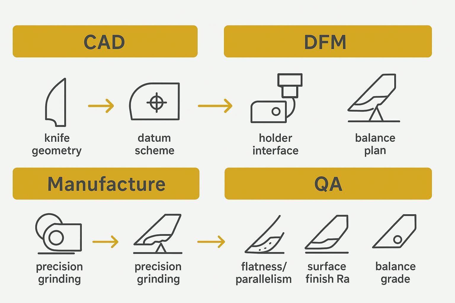
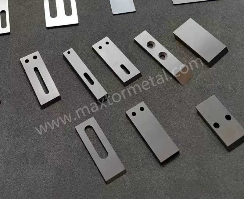
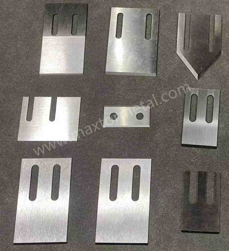
Custom pelletizer knives for underwater (water-ring/die-face) cutting don’t become production-ready by chance. They get there through a disciplined chain: CAD intent → DFM reality → controlled manufacturing → auditable QA → run-in validation on your line. In this guide, you’ll see how geometry, materials, precision grinding, and documentation come together to shorten run-in and extend service life—two levers that directly raise uptime and cut unplanned stops.
You’ll learn:
- What to capture in CAD so the knife shears cleanly at the die face.
- How to translate drawings into DFM that preserves edge integrity and fit-up.
- Which materials, joining methods, and coatings make sense for recycled and filled PE/PP.
- The metrology that matters: flatness, parallelism, edge land width, surface finish, and balance.
- What belongs in the QA packet and how to prove readiness at startup.
This helps plant, production, maintenance, and purchasing teams who need predictable pellets, fewer tails and fines, and knives that settle quickly and stay in spec longer.
Основные выводы
- Prioritize uptime: design and verify knives to reduce run-in time and extend intervals between changeovers.
- Tie specs to measurement: define flatness, parallelism, edge land width, surface finish (Ra), and balance with traceable methods.
- Stabilize shear at the die face: maintain uniform contact geometry and controlled spring/force so knife-to-die behavior is consistent.
- Choose materials and coatings by duty: match base steel or carbide and topcoats to recycled/filled PE/PP heat and abrasion profile.
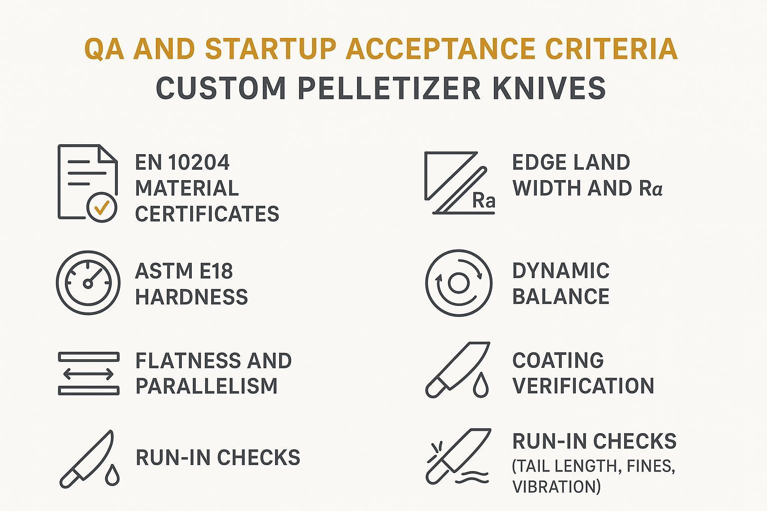
- Require a complete QA packet: material certs, hardness, coating checks, dimensional/balance reports, plus a run-in checklist.
- Validate on your line: use acceptance criteria (tails, fines, vibration) to confirm production readiness before full-scale.
CAD-to-DFM fundamentals for underwater cutting
Geometry essentials that stabilize shear at the die face
Clean, repeatable shearing at the die face depends on consistent geometry across the entire knife set. In CAD, define a clear datum scheme so grinding references aren’t ambiguous later. Capture the working edge geometry (macro rake/clearance and the micro “edge land”) as separate, inspectable features. Keep the cutting edge straightness and planarity correlated to a primary datum surface so knife-to-die contact is uniform when the cutter is loaded.
Because public, OEM-specific numeric targets vary, treat numeric examples as typical and focus on method. Specify flatness and parallelism as GD&T controls (ASME Y14.5 / ISO 1101 families) tied to functional datums. That lets you verify that the knife sits and sweeps evenly, minimizing local high spots that cause intermittent contact, heat, and premature wear. Surface texture (ASME B46.1 / ISO 21920 series) at the edge land should be low enough to avoid micro-tearing and fines.
Functionally, the goal is a minimal, controlled knife-to-die interface that stays stable as thermal conditions change. Systems that apply a constant spring or compliant force at the cutter help keep contact behavior consistent as components grow or shrink with temperature, which supports steadier pellets and fewer excursions, as OEM documents on underwater pelletizing systems describe from a system perspective (see MAAG’s tempered water and underwater pelletizing briefs for context).
Holder interface, balance, and retrofit fit-up
Your CAD must match the holder’s locating and clamping scheme—hole pattern, counterbore depths, reliefs, and any pins or steps—so stack-up doesn’t shift the edge where you don’t intend it. Model and tolerance the assembled center of mass and plan for dynamic balancing of the rotating cutter assembly. Reference balancing practice using ISO 21940-11 grade concepts (e.g., G2.5–G6.3 class targets by speed/rigidity) and specify verification in one or two planes as appropriate.
For retrofit into Gala/MAAG ecosystems, capture critical dimensions that preserve OEM offsets and sweep envelope. A small mislocation at the mounting face can become a large edge-position error at radius. Guard against tolerance stack-ups with clear datums and perpendicularity controls.
Setup forces and cooling water factors to control tails
Knife-to-die force that’s steady and within the machine’s intended range reduces chatter, edge chipping, and tail formation. Many underwater systems use mechanisms that keep a constant force on the cutter so operators aren’t constantly chasing contact. Cooling water flow and temperature also influence tailing and fines by affecting pellet solidification and transport. MAAG’s documents on tempered water systems explain how closed-loop flow and moderated temperatures stabilize the process, which indirectly supports cleaner cuts and fewer defects.
OEM documentation connects these parameters to outcomes: closed-loop water circuits that hold a moderated setpoint and ensure adequate, uniform flow stabilize pellet solidification and transport, which reduces tailing and fines. This control logic is outlined in MAAG’s Tempered Water Systems brief and reinforced in ECON’s EWT tempered water system overview, which describes temperature setpoint regulation and flow distribution to keep cutting conditions steady at the die face.
Materials, heat treatment, joining and coatings
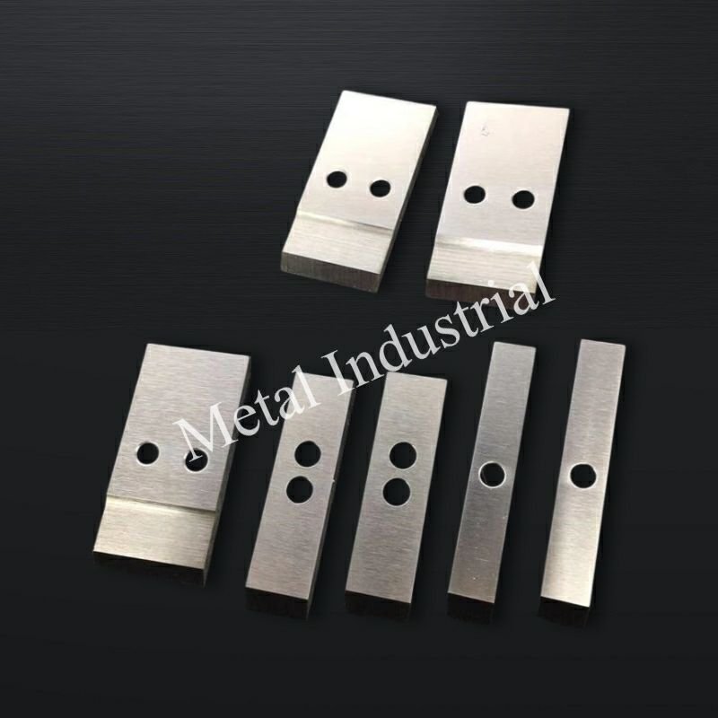
Base steels vs. carbide edges for recycled and filled PE/PP
Match the edge material to the duty. D2 is a common baseline for general-duty thermoplastics. For hotter runs or higher abrasion, high-speed steels (e.g., M2) or PM high-vanadium tool steels offer improved hot hardness and wear resistance. In streams with glass/mineral fillers or contaminants typical of recycled PE/PP, carbide-tipped or full-carbide edge solutions preserve sharpness longer and help extend intervals between changeovers. OEM and reputable supplier literature on underwater pelletizing tools highlights carbide’s role where abrasion dominates.
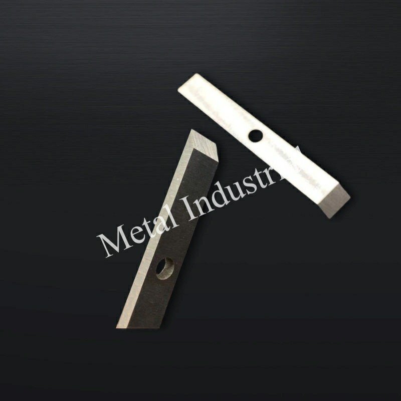
Vacuum heat treat, brazing, and HIP for bond strength
Vacuum heat treatment keeps surfaces clean and reduces oxidation, which improves dimensional control and edge quality. When joining carbide to a steel body, use qualified brazing processes (in vacuum or controlled atmosphere) with appropriate filler selection and joint design, and consider hot isostatic pressing (HIP) to densify interfaces or PM substrates and improve bond integrity. Third-party resources describing vacuum brazing and HIP provide the process rationale; your QA should reflect joint cleanliness, filler specification, and post-braze inspection.
Coating and non-stick topcoat selection by duty and heat
Hard PVD/CVD coatings such as TiN or DLC can raise surface hardness and lower friction where abrasive or high-temperature service would otherwise accelerate wear. In sticky recycled streams, a non-stick topcoat (e.g., PTFE-type) on non-critical faces can reduce adhesion and ease cleaning. Choose coatings that survive your thermal envelope and won’t spall at the edge during run-in.
A neutral example of a QA-backed custom-fit workflow: МАКСТОР МЕТАЛЛ supports manufacturing to customer drawings or samples with material selection options (e.g., D2/M2/PM steels, carbide-tipped designs), vacuum-brazed joints via partners, and optional hard and non-stick coatings, delivered with inspection records for flatness/parallelism, surface finish, and hardness. Disclosure: MAXTOR METAL is our product. For background on tolerances and QA practices, see MAXTOR’s resources on an industrial blade tolerance guide and a quality and inspection overview.
Precision grinding and dimensional control
Flatness and parallelism targets for consistent contact
Flatness and parallelism keep the knife’s working faces seated so the edge sweeps the die uniformly. Specify flatness as a form control relative to a primary datum surface and parallelism to align secondary faces. Verification can use a granite plate and dial indicator mapping, bridge/arm CMMs (validated per ISO 10360 families), or optical systems. Because public, pelletizer-specific numbers are scarce, many plants use “typical” ranges informed by function and instrument resolution; the important part is to record the method, instrument, and uncertainty on the inspection report. For reference on flatness concepts and measurement methods, see metrology primers from instrument makers.
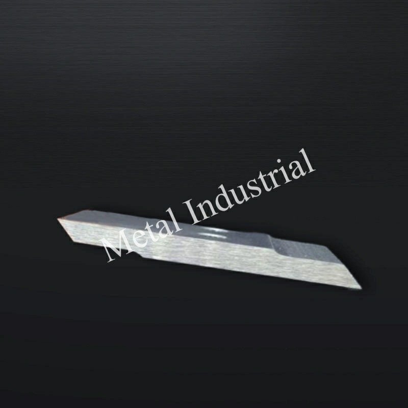
Edge land width and surface finish for low fines
The edge land is the micro-geometry that stabilizes the cut. Too wide and you push and heat; too narrow and you chip and shed fines. Treat land width and surface texture as inspectable features. Optical or contact profilometry can quantify land width and Ra. Grinding should deliver a crisp land with a low-Ra finish that reduces micro-tearing without sacrificing bite. Knowledge pages from cutting-tool vendors on surface generation and finishing parameters provide transferable principles for achieving low Ra at edges.
Third-party evidence links edge micro-geometry to burrs/fines via the same ploughing-versus-shearing mechanism discussed here. In a simulation-plus-experiment study, larger tool tip radius increased outlet burrs because more material was pushed (ploughed) instead of cleanly sheared, as shown in MDPI’s 2023 Micromachines burr formation study. Likewise, when the undeformed chip thickness approaches the edge radius, ploughing dominates and burrs and roughness rise, according to Copernicus’ 2021 Mechanical Sciences micro end milling study. While these tests are on metals at micro-scale, the deformation mechanics map to polymer shearing at the die face: a narrower, crisp edge land (and low-Ra finish) maintains a shearing-dominant regime and helps suppress fines; an over-wide land or rounded edge shifts toward ploughing and increases fines generation. Record land width and Ra in your inspection plan so the micro-geometry that governs this mechanism is controlled lot-to-lot.
Datum schemes and Gala/MAAG-compatible tolerances
Define datums that mirror how the knife assembles to the holder and hub. Use position and perpendicularity to control hole patterns and faces that set the knife’s sweep plane. Include a balancing requirement for the rotating cutter assembly with verification to an appropriate grade under ISO 21940-11 concepts, noting the speed and correction plane count. For retrofit into Gala/MAAG ecosystems, include the critical interfaces and offsets in the drawing so manufacturing and incoming inspection can verify fit before shipment.
QA documentation and run-in validation
Material certs, hardness, and coating verification
Your QA packet should include material certificates (commonly EN 1024 3.1 for metallic products) showing heat and chemistry, along with hardness results measured and reported to ASTM E18 conventions with NIST-traceable test blocks. When coatings are used, document the type, thickness range, and adhesion verification method. If braze joints are present, note filler specifications and any visual/NDT checks performed.
Dimensional inspection report with traceable instruments
The dimensional report should list each controlled feature—flatness, parallelism, edge land width, hole positions—with the measurement method, instrument, and calibration status. If a CMM is used, include the machine verification reference (ISO 10360 families), probe type, and environmental conditions. For surface texture, record Ra measurement parameters. Keep link density low, but ensure the report includes enough detail that another lab could repeat the measurements.
To accelerate adoption and make the packet instantly actionable, include reusable assets: a version-controlled QA inspection checklist and a dimensional inspection report template (CSV/PDF) that mirror the features listed above. You can access our house templates and see how we verify hardness (ASTM E18), surface texture (Ra), and CMM traceability in our Quality and inspection overview.
Run-in checklist and acceptance criteria at startup
Before full-rate production, prove readiness on your line with a structured run-in. Verify knife-to-die contact, cutter force mechanism function, and water system setpoints (flow and temperature) per your machine’s procedure. Sample pellets for tail length distribution and fines percentage after a brief stabilization window; record vibration at the cutter housing as a proxy for balance and fit. Define acceptance criteria that fit your product and customer expectations (e.g., tail occurrences within a defined ppm or percentage window, fines below a threshold), and capture results in a startup report.
Failure modes and preventive SOPs
Die plate grooving and accelerated wear mitigation
Persistent knife contact at high local pressure can groove the die plate, degrading cut quality and causing heat and tails. Mitigate by ensuring uniform contact geometry, verifying cutter force mechanisms, and resurfacing die faces on a schedule tied to observed wear. OEM literature on underwater pelletizing systems also points to protective measures and coatings on die faces; use them where appropriate and monitor groove depth during planned stops.
Edge chipping, vibration, and tolerance stack-up control
Chipping at the edge usually signals an unstable contact pattern or vibration from imbalance or misfit. Control the stack-up with disciplined datum use, verify dynamic balance of the rotating assembly, and inspect hole locations and mounting faces. If you see rising vibration or noise at the housing, treat it as a leading indicator and correct before the edge deteriorates.
Resin buildup control for sticky recycled streams
For stickier, recycled streams, aim to prevent adhesion on non-critical knife faces with a suitable non-stick topcoat and keep water temperature/flow within the machine’s recommended envelope. Establish a cleaning SOP that removes buildup without rounding the edge land; verify with a quick optical check before restarting.
Micro-case (anonymized field trial): A North American plastics recycler running a Gala-compatible underwater pelletizer tested a tolerance-and-materials upgrade (tightened flatness/parallelism controls, carbide-tipped edges, and verified run-in SOPs). Baseline: 6–8 hour run-in, changeovers every 72 hours, tails/fines ~1.8% by weight, and housing vibration peaks ~4.5 mm/s. After implementation (6-week trial): run-in fell to 1–2 hours, changeovers extended to 160 hours, tails/fines dropped to ~0.5%, and peak vibration reduced to ~2.0 mm/s. Customer requested anonymized reporting; data shown are from supplier-verified production logs.
Заключение
Specifying and validating custom pelletizer knives isn’t about guesswork. It’s about translating CAD intent into a manufacturable edge, holding flatness/parallelism and micro-geometry through precision grinding, and proving it with traceable QA—and then confirming on your line that the set runs smoothly. When you tie those steps together, run-in times shrink and changeover intervals stretch, lifting uptime while cutting unplanned stops.
Next steps: lock in your datum scheme and measurement methods on the drawing; standardize the QA packet you’ll require from any supplier; confirm retrofit-critical dimensions against your Gala/MAAG ecosystem; and use a startup checklist with defined acceptance criteria to validate production readiness. For deeper background on tolerances and inspection practices in blade manufacturing, see the internal resources mentioned above and OEM/system documents on underwater pelletizing and tempered water systems.
References and further reading (selected, descriptive anchors):
- OEM system context on underwater pelletizing and tempered water systems can be found in MAAG’s briefs on the Underwater pelletizing systems and the Tempered water systems.
- Geometric tolerancing and surface texture frameworks: see the ASME portal for Y14.5 and B46.1 families and ISO’s index for geometrical product specifications.
- Metrology explainers for flatness and roughness: Keyence flatness explainer; Keyence optical roughness overview.
- Balancing practices and grades context: Schenck HM balancing machines and ISO 21940-11 grade background via the ISO index.
- QA documentation norms for hardness and material certs: ASTM E18 Rockwell hardness and EN 10204 certification types via BSI overview.