

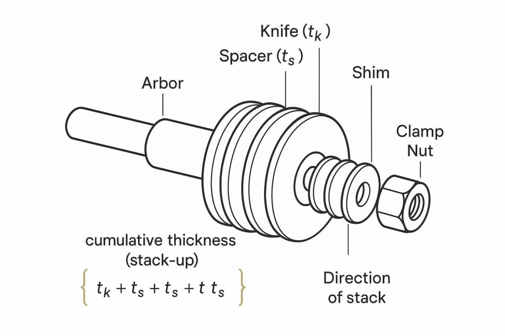
Maxtor Metal производит прецизионные промышленные ножи по индивидуальному заказу для линий переработки и продольной резки. В повседневной работе по резке один из самых быстрых способов потерять стабильность ширины реза (и OEE) — это игнорировать влияние небольших погрешностей толщины при наборе большого количества ножей, проставок и регулировочных шайб на одном валу.
- Define cumulative thickness tolerance: the total axial thickness variation of the assembled knife pack after all individual part tolerances and setup effects combine.
- Почему это важно: cumulative variation shows up as slit width drift, clearance changes, burrs, edge damage, rework, and longer changeovers.
- Where it comes from: knives, spacers, arbor features, shims, runout, clamping distortion, cleanliness, and temperature.
- What this guide covers: stack-up math (worst-case vs RSS), quality effects, and the control loop needed to pursue targets as tight as ±0,001 мм (when the process and measurement system justify it).
- Engineering Note: Cumulative thickness tolerance control is just one aspect of rotary tooling precision. For knife-level specifications including axial runout standards and material grades, see Maxtor Metal’s Precision Circular Slitter Kniveс.
Basics of cumulative thickness tolerance
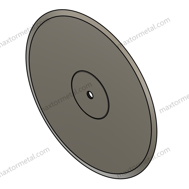
Definition and terms
Cumulative thickness tolerance (stack-up) is the maximum expected variation in the assembled stack height when you combine multiple components in series. In a multi-knife slitting lane, that stack height sets the axial positions of knives and spacers, which in turn sets clearances and—ultimately—slit width and edge condition.
Key terms used in this article:
- Nominal thickness: the target thickness of a knife or spacer.
- Толерантность: the allowed deviation from nominal (often bilateral, e.g., ±0.003 mm).
- Stack height: the sum of all component thicknesses in the lane.
- Axial shift: the net position error across the stack due to accumulated variation.
- TIR (total indicator runout): the measured variation as a part rotates; it can act like a “dynamic” contributor even when thickness is perfect.
Sources of stack error
Stack error is rarely “just the knives.” It’s the combination of component variation and assembly realities:
- Knife thickness tolerance (and parallelism/flatness contributing to effective thickness).
- Spacer thickness tolerance (often the largest cumulative contributor because there are many spacers).
- Arbor shoulders, journals, and seating surfaces (axial reference geometry and wear).
- Прокладки (thickness tolerance + handling damage).
- Runout / wobble (TIR) from arbor condition, bearing wear, nicks, burrs, or eccentric bores.
- Clamp distortion from torque, pack compression, and non-uniform contact.
- Температура (machine warm-up, frictional heating, ambient swings).
Ключевой вывод: When you’re chasing tight slit-width tolerances, treat runout, cleanliness, and thermal state as first-class stack contributors—not “setup noise.”
Impact on slit width and edges
Cumulative thickness tolerance matters because it changes where the knife edges actually run under load.
Common symptoms when stack-up isn’t controlled:
- Slit width variation across lanes or across time (start vs warm operation).
- Burr formation because clearance shifts out of the stable window.
- Edge tearing/fuzzing on films and nonwovens when the cut transitions from shear to rub.
- Knife collisions or scuffing when cumulative axial shift eliminates safe side clearance.
The practical link to OEE is straightforward: width and edge issues increase scrap and line interruptions, while frequent “micro-adjust” stops extend changeovers.
Stack-up methods and examples
This is where tolerance stack-up becomes a practical tool: you choose a method, run the numbers, and then decide what you must control (and what you can safely leave looser).
Worst-case vs RSS stack-up
There are two common ways to estimate cumulative thickness tolerance. They answer different questions.
- Worst-case assumes every contributor hits its extreme limit in the same direction.
- RSS (root-sum-square) assumes contributors are largely independent and random, so extremes rarely align.
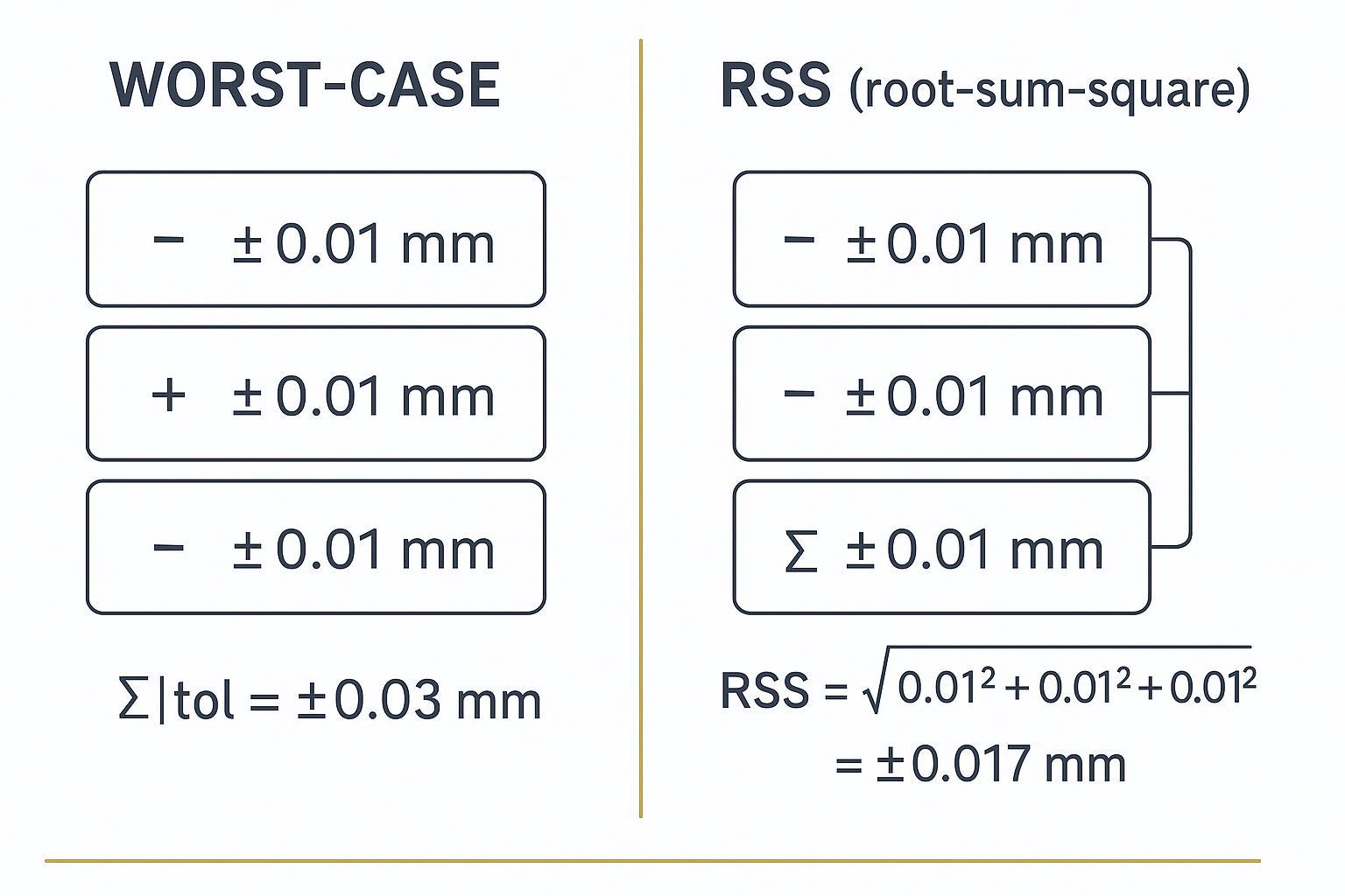
Use cases:
- Использовать worst-case to protect against hard interference limits (fit, collision risk).
- Использовать RSS to estimate expected production variation when the process is stable and measurement is credible.
A simple way to keep the math honest: RSS is a prediction, but your first-article width and edge data is the truth—use production data to validate or update the tolerance budget.
For a clear engineering overview of both methods and their assumptions, see Enventive’s explainer on worst-case, RSS, and Monte Carlo in tolerance stackups (2024).
For broader GD&T and tolerancing context, many engineering teams also reference standards frameworks such as ASME Y14.5 Dimensioning and Tolerancing and the ISO limits-and-fits system (e.g., ISO 286-1:2010) when defining tolerances and interpreting stack-up risk.
Numeric example for a multi-knife lane
Consider a single lane with:
- 1 top knife + 1 bottom knife (thickness variation affects how the pack seats)
- 8 spacers
- 2 shims
If each spacer is specified at ±0.003 mm, the shims at ±0,002 мм, and each knife at ±0,002 мм, then:
Worst-case stack tolerance (simple bilateral sum):
- Spacers: 8 × 0.003 = 0.024 mm
- Shims: 2 × 0.002 = 0.004 mm
- Knives: 2 × 0.002 = 0.004 mm
- Total worst-case = ±0.032 mm
RSS estimate (assuming independence):
- RSS = √(8×0.003² + 2×0.002² + 2×0.002²)
- RSS = √(8×9e-6 + 4×4e-6)
- RSS = √(72e-6 + 16e-6) = √(88e-6) ≈ ±0.0094 mm
Both numbers can be “right,” depending on what you’re trying to protect.
Building a tolerance budget
A tolerance budget makes stack-up actionable instead of theoretical.
- Define the output you care about
- Slit width tolerance (e.g., ±0.05 mm) or side clearance window.
- List contributors and classify them
- Random (measurable scatter): thickness variation of ground spacers.
- Systematic (bias/correlation): clamp torque procedure, warm-up state, dirty seating faces.
- Allocate budget by leverage (impact) and controllability
- Many shops get more benefit by tightening spacer control and runout than by over-tightening every knife thickness.
- Bind the budget to measurement confidence
- If your micrometer + method can’t reliably resolve the tolerance band, the budget is paperwork, not control.
A practical rule for stack components: the more pieces you have in series, the more you should consider measured-and-matched sets instead of trusting nominal labels.
Mini case study: flexible packaging film slitting (BOPP/PE)
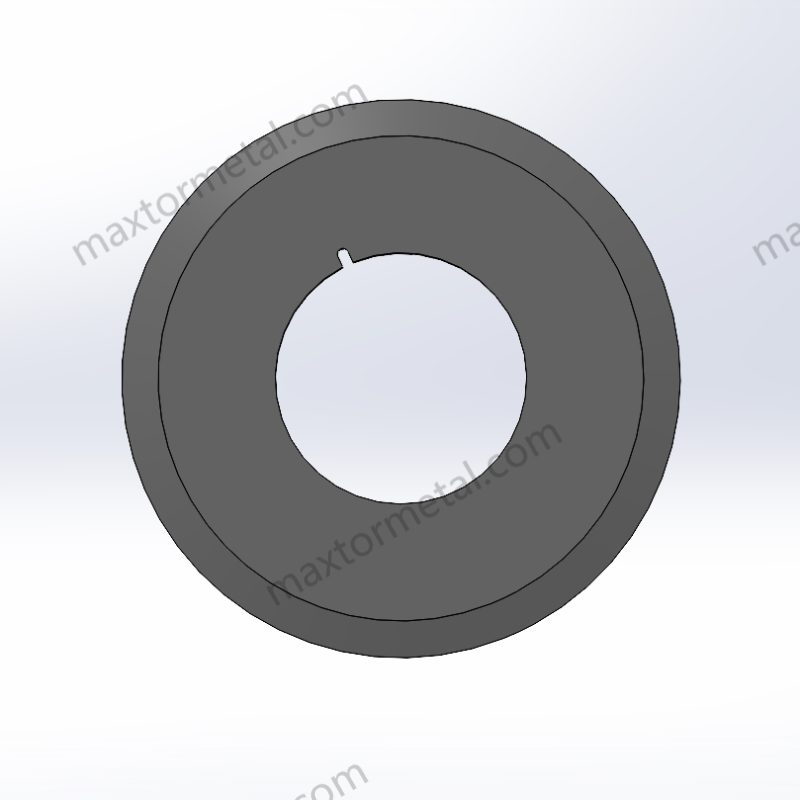
The data below comes from Maxtor Metal’s project support for a flexible packaging film converter; the customer name has been anonymized.
The fastest way to make stack-up “real” is to tie it to one lane’s numbers. The following anonymized example comes from a flexible packaging film converter running a differential rewind slitting line.
Настраивать
- Material/process: BOPP / PE flexible packaging film
- Knife stack (per setup): 18 circular slitter knives, 36 spacer/separator rings, thin shims used for final width correction
- Knife shaft diameter: 120 mm
Original problem
After knife changes, the converter saw slit width drift, light edge burrs, and unstable setup repeatability (repeat customer complaints).
Control actions implemented
- Spacer rings measured individually and marked
- Spacers sorted in 0.001 mm thickness groups и paired/matched during assembly
- Defined tightening torque + tightening sequence, с pre/post-torque TIR recorded each setup
- Added a cleaning + deburring procedure for all knife/spacer contact surfaces
Results (before vs after)
| Метрическая | Before improvement | After improvement |
|---|---|---|
| Slit width variation | ±0.080 mm | ±0.025 mm |
| Burr / edge defect rate | 4.8% of rolls | 1.2% of rolls |
| Время переналадки | 52 min | 34 min |
| Pre/Post-torque TIR | 0.014–0.018 mm | 0.005–0.007 mm |
| Spacer thickness spread (total) | 0.006 mm | 0.002 mm |
Measurement notes (what made the data defensible)
One detail worth calling out: the converter didn’t start by switching knife materials or changing suppliers. The first gains came from making the stack measurable and repeatable (spacer matching, torque discipline, and TIR logging) and then letting the data drive whether tighter part tolerances were justified.
- Spacer thickness measured using a digital micrometer with 0.001 mm resolution
- Measurement repeated 3 times per spacer
- Measurements performed in a temperature-controlled inspection room (~20°C)
- First-roll slit width and edge condition recorded after each setup; stability maintained across 3 consecutive production batches
Takeaway: Before tightening knife thickness specs to micron levels, stabilize the system: match spacers by measured thickness, standardize torque, and log pre/post-torque TIR. In many real lines, these controls deliver faster and larger gains than tightening a knife-only callout on paper.
Case study template (copy/paste)
- Material + slitting method:
- Knife count / spacer count / shim use:
- Target slit width tolerance:
- Spacer thickness spread (min/max or total):
- Pre/post-torque TIR:
- Before/after: width variation, edge defect rate, changeover time:
- Measurement method + temperature condition + repeat count:
Precision targets and capability
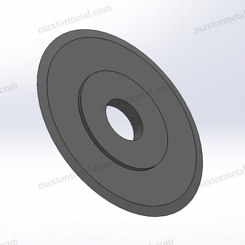
Typical vs high-precision specs
Not every slitting line needs micron-class thickness tolerance.
Typical bands you’ll see in converting and slitting:
- General film/tape/paper slitting: thickness tolerance around ±0,005 мм can be reasonable when combined with good setup discipline.
- Heavier-duty or more demanding lines: ±0.003 mm may be used.
- Ultra-precision applications (foil/electrode, critical edge quality): ±0.001 to ±0.002 mm is sometimes specified.
Those ranges align with application guidance published on the Maxtor Metal circular knives and blades product page (including a clear note that cumulative error across a multi-blade gang can create burrs or collisions if per-blade thickness variation is too large).
When ±0.001 mm is justified
А ±0,001 мм thickness target is a tool, not a badge. It’s justified when at least one of the following is true:
Before you escalate to micron-level targets, run one quick reality check—and a decision gate:
- Measurement capability check (fast screen): if your micrometer/comparator, method, and environment can’t consistently distinguish a 1–2 μm difference on the same part (repeat reads with the same operator), you’re not ready to enforce ±0,001 мм in production.
- Decision gate (go/no-go): don’t tighten to ±0,001 мм unless you can (1) demonstrate acceptable GR&R (or equivalent repeatability screen) for the tolerance band, (2) control measurement conditions (force/fixturing and temperature state), and (3) show that thickness-driven stack variation correlates with the width/edge problem.
- Decision rule: treat ±0,001 мм как system specification (parts + gauging + thermal control + setup procedure), not a knife-only callout.
- The slit product tolerance is very tight, so stack-induced axial shift consumes too much of your width budget.
- The process window for clearance is narrow (edge quality collapses quickly outside it).
- You have enough knives in the pack that “small” per-part tolerance becomes a real axial drift.
- You have evidence that thickness variation—not runout, alignment, or tension—is the dominant driver.
If you can’t verify the measurement and the process capability, a ±0.001 mm specification can increase cost without improving scrap or uptime.
Capability, Cp/Cpk, and GR&R
Two checks keep precision targets honest:
- GR&R (gage repeatability and reproducibility): confirms your measurement system is stable enough. If measurement noise is a large fraction of the tolerance band, you’ll chase ghosts.
- Cp/Cpk: confirms your process output (slit width, edge defects, clearance measurements) is capable and centered.
Practical expectations:
- If Cpk is low, don’t start by demanding tighter knife tolerances—first find whether the process is off-center (setup bias) or truly too variable (component scatter).
- If GR&R is weak, fix instruments, fixturing, method, and environment before changing specs.
Manufacturing and metrology path
Materials, heat treat, and stress relief
Thickness tolerance stability starts before grinding.
- Выбор материала affects how predictable grinding and distortion are after heat treat.
- Heat treat and stress relief influence flatness, parallelism, and long-term stability.
- Process documentation matters because it enables root-cause work when edge quality drifts.
In practice, the “metrology path” is strongest when every batch can be tied to material certs, heat-treat records, and inspection results. Maxtor Metal maintains batch-level traceability through material certs, heat-treat records, and part inspection logs — documentation that allows root-cause work when edge quality drifts after installation.
Grinding, lapping, and surface finish
To control thickness at the micron level, you need process choices that are built for it:
- Parallel grinding strategy designed for thickness consistency (not just edge geometry).
- Thermal control during grinding to reduce distortion.
- Lapping or finish grinding when surface and parallelism drive fit.
Surface finish also shows up downstream as edge quality and contamination:
- For high-speed film converting, very smooth faces reduce friction and debris.
- For abrasive coatings or filled polymers, finish requirements and edge prep should match the wear mode.
Gauging, environment, and traceability
When targets approach ±0.001 mm, treat measurement as an engineered system:
- Gauging: use calibrated micrometers/comparators suited for microns; document force technique.
- Среда: temperature stability matters; measure at defined thermal states.
- Traceability: keep calibration records and part-level inspection logs so “good parts” are defensible.
If you’re buying precision components internationally, traceability plus a predictable import workflow reduces two common failure modes: (1) you can’t prove what you received, and (2) the parts arrive late and force an emergency changeover plan.
Slitter setup and maintenance
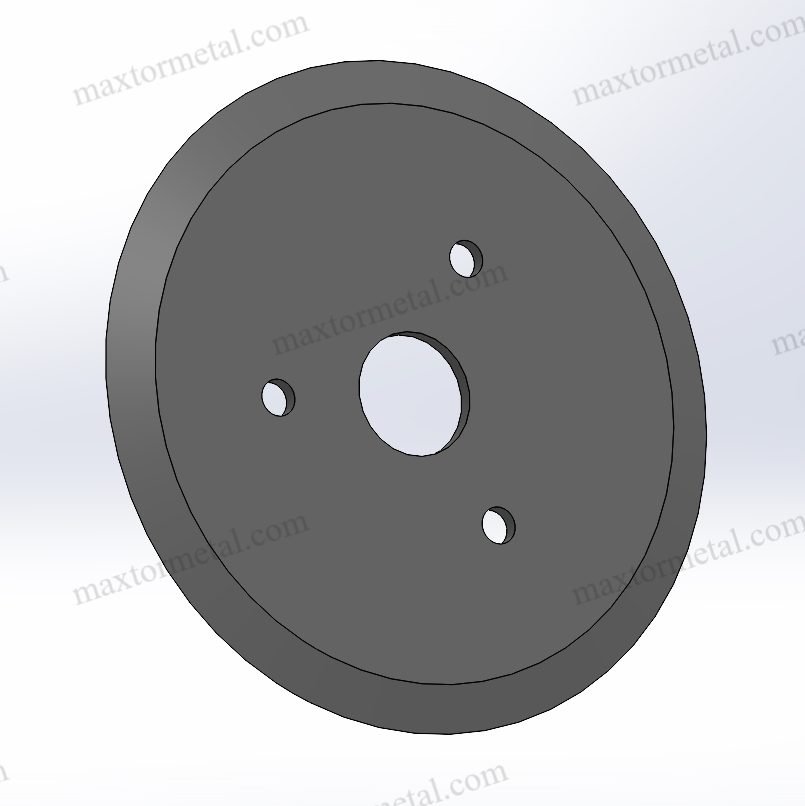
Arbor and runout checks
Runout can dominate stack-up. A thin film line may tolerate modest variation; a tight-width, high-speed job may not.
For a deeper look at how central bore tolerance and ISO 286 fit selection affect assembled TIR—and a verification routine to keep runout repeatable across changeovers—see Допуск на центральное отверстие и биение: оптимизация посадки по стандарту ISO 286 для высокоскоростных ножей для продольной резки..
Что необходимо проверить:
- Arbor journal condition (nicks, wear bands).
- Shoulder seating faces (burrs, trapped debris).
- Bearing condition (heat, vibration signatures).
- Assembled pack TIR after torque.
If you need a technical refresher on how alignment and movement upstream of the slit point affect achievable tolerances, Parkinson Technologies discusses practical constraints in Achieving Tight Tolerances with Wrap Shear Slitting (2023).
Spacer calibration and match grinding
Spacer control is often the highest-return improvement because it’s both measurable and repeatable.
A workable spacer discipline:
- Measure every spacer and mark the actual thickness.
- Sort into bins by measured value (e.g., 0.001 mm increments).
- Build lanes using matched sets rather than random pulls.
- Re-measure after any damage event, polishing, or suspected burr.
Match grinding (or lapping) becomes relevant when:
- You need repeatable lane widths across many packs,
- You want to reduce the number of shims used, or
- You need predictable behavior after torque.
Clamp torque, overlap, and alignment
Even a “perfect” stack can fail if assembly bias is uncontrolled.
- Torque: define a procedure (tool, torque value, sequence) and keep it consistent.
- Перекрывать and side clearance: set to the material and process window; verify after torque.
- Выравнивание: ensure top/bottom knife relationship is stable across the run.
A simple but effective control is to record three numbers each setup:
- pre-torque TIR
- post-torque TIR
- first-article width and edge inspection result
If those three are stable, your tolerance budget has a chance of being real.
For lines running thin films or nonwovens where holding a fixed clearance is impractical, see how spring-loaded zero-clearance setups handle this: Подпружиненная настройка для резки сдвигом с нулевым зазором.
Economics and risk trade-offs
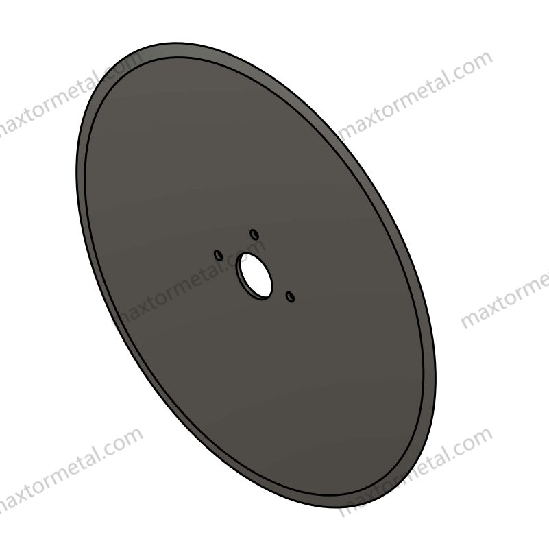
OEE and scrap cost model
Cumulative thickness tolerance problems typically cost money in three places:
- Scrap: width out-of-spec or edge defects.
- Время простоя: extra time to chase clearance and re-stack packs.
- Tooling life: rubbing and collisions shorten knife life and increase regrind frequency.
A quick model you can apply:
- Scrap cost per hour = (scrap rate %) × (throughput) × (material cost)
- Downtime cost per event = (minutes lost) × (line $/minute)
- Tooling cost delta = (extra regrinds + replacements) × (unit cost)
When you quantify those three, it becomes clear when “tighter tolerance” pays back—and when it doesn’t.
Lead time and tooling cost impacts
Tighter tolerances usually increase:
- grinding and inspection time,
- rejection rate at the supplier,
- metrology requirements (and therefore cost).
They can also reduce total cost if they cut setup time and scrap enough to dominate the tooling premium. The only way to know is to bind tolerances to measured outcomes (width scatter, edge defect rates, and changeover minutes).
Decision flow for precision level
Use this decision flow to choose a precision level without guessing:
- Is the defect clearly tied to runout/alignment/cleanliness?
- Yes → fix setup and maintenance first.
- No → continue.
- Does measured lane-to-lane width variation correlate with measured component thickness variation?
- Yes → tighten the tolerance budget where it contributes most (often spacers first).
- No → continue.
- Can your measurement system pass GR&R for the tolerance band?
- No → upgrade measurement and environment.
- Yes → continue.
- Does the scrap + downtime model justify the premium for tighter components?
- No → keep a practical spec (±0.003 to ±0.005 mm) and improve controls.
- Yes → pursue ±0.001 mm with full traceability and capability checks.
Assumptions and applicability (to avoid over-specifying)
A stack-up calculation is only as good as its assumptions. Use this guide with the following practical boundaries:
- Worst-case vs RSS: worst-case protects against hard interference limits (rubbing/collision risk). RSS estimates typical variation when contributors are mostly independent.
- Correlation matters: parts from the same grinding batch, the same clamping procedure, or a consistent setup bias can make errors move together. If you see correlation, RSS can under-predict—use worst-case for safety and verify with real measurements.
- Micron targets require a capable measurement system: before specifying ±0,001 мм, confirm your measurement method, force control, and temperature conditions can resolve the band. If the gage can’t pass GR&R at that tolerance, you’ll make decisions based on noise.
For deeper background on measurement system analysis (GR&R/MSA) and capability indices (Cp/Cpk), see ASQ’s overview of Gage R&R, AIAG’s description of the MSA-4 Measurement Systems Analysis manual, ASTM’s E2782 guide for Measurement Systems Analysis (MSA), and JMP’s primer on process capability.
Заключение
Cumulative thickness tolerance in multi-knife slitting is a stack-up problem: small errors in knives, spacers, shims, arbor geometry, runout, and thermal state add together and show up as width drift, edge defects, and lost OEE. The fastest path to stability is to treat the whole system—components + measurement + setup—as one tolerance budget you can verify.
Based on Maxtor Metal’s measured experience supporting multi-knife slitting projects, controlling spacer thickness and assembly discipline often delivers faster improvements than simply tightening a knife thickness tolerance on paper.
Immediate steps you can apply this week:
- Measure arbor and assembled-pack TIR before and after torque.
- Start a spacer measurement-and-sorting discipline (actual thickness marking).
- Separate worst-case (hard interference) from RSS (expected variation) in your tolerance math.
- Confirm GR&R before declaring a micron-level spec “necessary.”
Quick reference (formulas + setup checklist)
Tolerance stack-up math
- Worst-case stack tolerance (hard-interference safety):
T_WC = Σ |t_i| (i = 1..n)
- RSS stack tolerance (expected variation when contributors are mostly independent):
T_RSS = sqrt(Σ (t_i^2)) (i = 1..n)
Typical thickness tolerance targets (rule-of-thumb)
These are starting points—validate them against your slit-width spec и measurement capability.
- ±0,005 мм: general converting where setup discipline is strong and clearance window is forgiving
- ±0.003 mm: demanding lines or higher knife/spacer count stacks
- ±0.001 to ±0.002 mm: ultra-precision jobs only when GR&R and process capability justify it
Setup checklist (record on every changeover)
- Clean shoulders, seating faces, and spacers (no burrs, trapped debris)
- Записывать pre-torque TIR и post-torque TIR
- Verify overlap/side clearance after torque
- Мера first-article width + perform edge inspection (burr/fuzz/tearing)
- Log spacer actual thickness (measured-and-matched sets)
To keep improvements from fading, keep these documents on file:
- component inspection records (thickness, parallelism, finish)
- gauge calibration and GR&R reports
- setup check sheets (torque method, TIR, first-article results)
- tolerance budget worksheet tied to your slit-width spec
FAQ
Вопрос: Что такое суммарный допуск по толщине при продольной резке?
Ответ: Это общая возможная вариация высоты собранного пакета ножей/проставок после учета всех индивидуальных допусков по толщине и эффектов сборки. При многоножевой резке эта суммарная вариация может сместить осевое положение ножей настолько, что это приведет к изменению зазоров и ширины реза.
Вопрос: Как рассчитать суммарный допуск (stack-up) для нескольких проставок и ножей?
Ответ: Используйте метод худшего случая (сумма абсолютных допусков) для защиты от жестких пределов интерференции и RSS (квадратный корень из суммы квадратов) для оценки ожидаемой вариации, когда параметры независимы, а процесс стабилен. Затем выполните валидацию с помощью измерений реальных деталей и результатов первой партии.
Вопрос: Анализ допусков: «наихудший случай» (worst-case) или RSS — что выбрать для ножевого инструмента?
Ответ: Используйте «наихудший случай» (worst-case), если потеря зазора может привести к трению или столкновениям, так как этот метод обеспечивает необходимый запас прочности. Используйте RSS для оценки типичного отклонения ширины при стабильном производстве, поскольку он лучше отражает поведение случайных вариаций.
Вопрос: Как биение вала (TIR) влияет на ширину реза и появление заусенцев?
Ответ: Биение создает динамическое осевое отклонение во время вращения пакета, что может вывести зазоры за пределы стабильного рабочего диапазона. Это может привести к периодическому трению, появлению заусенцев, перегреву и ускоренному износу, даже если допуски по толщине выглядят нормальными на бумаге.
Вопрос: Когда на самом деле необходим допуск по толщине ножа ±0,001 мм?
Ответ: Это необходимо, когда ваш допуск по ширине/кромке мал, количество ножей делает суммарную погрешность значительной, и вы можете доказать (с помощью измерений и корреляции), что именно вариация толщины — а не настройка или натяжение — является основным фактором. Это также требует измерительной системы с разрешением в микроны.
Вопрос: Какого значения GR&R ожидать при контроле толщины на микронном уровне?
Ответ: Вариативность вашей измерительной системы должна быть значительно меньше поля допуска, иначе вы будете принимать неверные решения из-за погрешностей измерения («шума»). Если GR&R неудовлетворительный, улучшите выбор прибора, оснастку (fixturing), методику и контроль температуры, прежде чем ужесточать спецификации деталей.
Вопрос: Почему проставки вызывают такую большую суммарную ошибку при многоножевой резке?
Ответ: Потому что их много в цепи. Даже небольшое отклонение на одну проставку становится значительным при умножении на всю высоту пакета, поэтому использование измеренных и подобранных по размеру проставок часто дает больше улучшений, чем ужесточение допусков для одного ножа.
Вопрос: Как уменьшить отклонение по ширине реза, не покупая новые ножи?
Ответ: Начните с контроля настройки: очистите привалочные поверхности, проверьте биение (TIR) вала и набора ножей, стандартизируйте крутящий момент затяжки и откалибруйте/рассортируйте проставки по измеренной толщине. Эти действия часто уменьшают вариативность быстрее, чем смена поставщика или материала. Также проверьте, соответствует соответствует ли геометрия фаски ножа механическому сопротивлению вашего материала.
After-sales Engineer: Jerry Chu
Title: Специалист технической поддержки
Организация: Послепродажное обслуживание
Reviewed by: Maxtor Metal QA Team
Опыт: 10 years, cross-industry applications (papermaking, plastic crushing, metal slitting, woodworking). Focused on solving on-site issues such as cutting burrs and excessive dust.
Сертификаты: PMP, CMRP

 English
  Spanish
  Italian
  French
  Portuguese
  Russian
  German
  Arabic
  Hindi
Hindi  Vietnamese
  Indonesian
  Japanese
  Korean