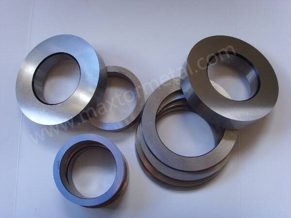
Tại Maxtor Metal, chúng tôi sản xuất dao xẻ vòng (slitter) và lưỡi dao cắt cuộn cho các dây chuyền xẻ băng kim loại tốc độ cao và máy cắt cạnh, nơi chúng hoạt động như các công cụ cắt chồng lên nhau. Thông qua các chuyển động quay đồng bộ giữa lưỡi dao trên và dưới, các công cụ này thực hiện việc cắt dọc liên tục, không phoi trên các cuộn kim loại cán nguội, cán nóng và hợp kim đặc biệt tiên tiến. Được thiết kế để chịu được tải trọng động nghiêm trọng, các công cụ này tích hợp hoàn hảo vào các môi trường gia công kim loại đòi hỏi khắt khe nhất thế giới.
1.1 Ma trận thông số kỹ thuật
Lớp tham số
Chi tiết thông số kỹ thuật
Máy móc tương thích
Được triển khai trên các dây chuyền xẻ rãnh chính xác cao toàn cầu và máy cắt cạnh, bao gồm... FIMI, SMS Group, Danieli, Andritz, Stamco và Herr-Voss Stamco. Yêu cầu tuân thủ tuyệt đối các hệ thống trục chính cứng vững, đòi hỏi độ cân bằng động cao và độ rơ dọc trục bằng không.
Các tùy chọn cơ sở vật liệu
Thép H13 tiêu chuẩn (4Cr5MoSiV1); Thép H13 cải tiến Cr-Mo-W; Thép H13 cải tiến Cr-Mo-Ni; Thép H13 cải tiến Cr-Mo-V-Mo; Thép H13 cải tiến hỗn hợp W+Ni; Thép H13 cải tiến hỗn hợp Mo+W; Thép gia công nguội DC53/LD hàm lượng Vanadi cao; Thép nền (Caldie / Viking); Thép tốc độ cao luyện kim bột hiệu suất cao (ASP 23 / CPM M4 / Vanadis 4 Extra).
* Dung sai độ dày: ±0,002 mm đến ±0,005 mm (Đường kẻ độ chính xác cao; khác với bản vẽ kỹ thuật thương mại tiêu chuẩn ±0,01 mm — xem Mục 4.3 để phân tích chi tiết)
* Độ phẳng và tính song song: <0,003 mm đến 0,005 mm
* Độ lệch trục: ≤0,005 mm (ngăn ngừa sự dao động khe hở định kỳ và các gờ sắc nhọn)
* Các mức dung sai không được ghi nhận: Tuân thủ tiêu chuẩn ISO 2768-mK.
Địa hình bề mặt
* Các cạnh cắt và mặt bên: Độ nhám bề mặt Ra <0,2μm đến 0,4μm nhờ quá trình mài siêu chính xác và đánh bóng gương. .
* Các bề mặt không dùng để làm việc: Ra <1,6μm.
Mục tiêu cắt xẻ
Thép cuộn cán nguội hàm lượng cacbon thấp, thép tấm cán nóng đã tẩy gỉ, thép tấm silic điện, dải hợp kim đồng/nhôm, thép không gỉ và thép siêu bền (UHSS, giới hạn chảy ≥900 MPa, giới hạn bền kéo lên đến ≥1200 MPa, chẳng hạn như thép dập nóng dùng trong ô tô, thép mactenxit và DP1180).
Tổng quan kỹ thuật về lưỡi dao cắt cuộn
2.1 Cơ chế của “Nén chịu lực cắt”
Cắt rãnh quay không phải là một quá trình tách đơn giản; đó là một hoạt động “nén mạnh và phức tạp” liên tục. Khi cuộn kim loại đi qua các lưỡi quay trên và dưới chồng lên nhau, vật liệu trải qua ba giai đoạn biến dạng riêng biệt:
Biến dạng đàn hồi: Điểm tiếp xúc ban đầu là khi cạnh dao tạo vết lõm trên bề mặt dải kim loại.
Kéo cắt nhựa: Lưỡi dao xuyên sâu hơn, đẩy vật liệu vượt qua điểm chảy dẻo dọc theo một mặt phẳng cắt cục bộ.
Khởi phát vùng đứt gãy: Các vết nứt siêu nhỏ lan truyền từ cả đầu dao trên và dưới cho đến khi chúng gặp nhau, tách vật liệu một cách gọn gàng mà không tạo ra phôi vụn.
Trong quá trình vận hành tốc độ cao, dụng cụ phải chịu những tác động cơ học tuần hoàn mạnh mẽ kết hợp với ma sát dữ dội dọc theo các cạnh lưỡi dao. Ma sát cục bộ này tạo ra nhiệt độ tức thời cực cao. Nếu vật liệu lưỡi dao thiếu độ ổn định nhiệt hoặc độ cứng khi nóng cần thiết, cạnh cắt sẽ nhanh chóng bị tôi luyện cục bộ, dẫn đến biến dạng dẻo, mài mòn nhanh và cuối cùng là sứt mẻ vi mô.
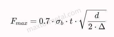
Lực cắt cực đại trên mỗi cặp dao được tính toán bằng cách sử dụng mô hình thực nghiệm sau:
Ở đâu:
Fmax là lực cắt cực đại trên mỗi cặp dao.
σb là độ bền kéo tối đa của vật liệu dạng dải.
t là độ dày của dải.
d là đường kính ngoài của lưỡi dao.
Δ là tổng độ sâu cắt (độ sâu xuyên thấu).
2.2 Chẩn đoán mài mòn vi cấu trúc
Để đảm bảo hiệu suất hoạt động ổn định của dụng cụ, cấu trúc vi mô của lưỡi dao phải có khả năng chống lại ba cơ chế mài mòn chính:
Mài mòn do bám dính (rè): Hiện tượng này chủ yếu xảy ra khi xẻ các vật liệu mềm hoặc có độ dẻo cao như thép không gỉ hoặc nhôm. Áp suất cao gây ra hiện tượng hàn vi mô cục bộ giữa dải vật liệu và cạnh lưỡi dao, làm bong tróc các hạt nhỏ của vật liệu nền lưỡi dao trong quá trình hoạt động.
Mài mòn do ma sát: Nguyên nhân là do các vi cấu trúc cứng (như oxit sắt trên các dải thép cán nóng đã tẩy gỉ hoặc cấu trúc cacbua silic có độ mài mòn cao trong thép điện) cày xới vào ma trận thép dụng cụ. Khả năng chống mài mòn phụ thuộc hoàn toàn vào tỷ lệ thể tích và sự phân bố đồng đều của các cacbua hợp kim sơ cấp (M).6C, MC, M23C6).
Mệt mỏi do nhiệt (Nứt do nhiệt): Chu kỳ nhiệt liên tục giữa nhiệt độ môi trường và nhiệt độ tức thời tạo ra ứng suất kéo và nén tuần hoàn tại mép cắt, dẫn đến hình thành các mạng lưới vết nứt nhiệt vuông góc ở cấp độ vi mô.
Ứng dụng công nghiệp của lưỡi dao cắt cuộn
3.1 Quy trình gia công thép siêu cứng UHSS trong ngành ô tô (Dây chuyền DP980 / DP1180)
Loại thiết bị: Dây chuyền xẻ rãnh chính xác, chịu tải nặng, độ cứng cao, trang bị trục khóa chống lệch chủ động.
Hồ sơ vật liệu công việc: Thép hai pha (DP), thép boron dập nóng dùng trong ô tô và thép mactenxit có độ bền chảy từ 900 MPa đến 1100 MPa.
Giải pháp vật liệu được đề xuất: Thép gia công nguội biến tính hàm lượng vanadi cao (DC53 / LD).
Khoảng hở kỹ thuật: Khe hở bên trục phải được thiết lập như sau: Từ 14% đến 18% là độ dày của tấm.. Việc thiết lập khe hở tiêu chuẩn không đủ để đảm bảo mặt phẳng cắt hoạt động trơn tru, gây ra sự tăng đột biến theo cấp số nhân về lực cắt, có thể dẫn đến gãy lưỡi dao nghiêm trọng.
Giới hạn thông số vận hành: Tốc độ cắt tối đa nên được điều chỉnh trong khoảng 80 m/phút đến 120 m/phút để kiểm soát va chạm cơ học và tải nhiệt lên các ranh giới hạt đã được tinh chế.
3.2 Cắt thép silic điện tốc độ cao
Loại thiết bị: Dây chuyền máy cắt vòng lặp siêu chính xác, giảm rung, hoạt động ở tần số cao.
Hồ sơ vật liệu công việc: Tấm thép silic điện không định hướng và định hướng hạt (độ dày từ 0,20 mm đến 0,50 mm) có hàm lượng silic mài mòn cao.
Giải pháp vật liệu được đề xuất: Vật liệu composite Mo+W cải tiến H13 hoặc thép tốc độ cao luyện kim bột hiệu năng cao (ASP 23).
Khoảng hở kỹ thuật: Khe hở bên trục được khóa chặt ở mức Độ dày dải từ 8% đến 10%; sự chồng chéo xuyên tâm được kiểm soát chính xác trong phạm vi Từ 2 mm đến 0,4 mm.
Giới hạn thông số vận hành: Tốc độ cắt lên đến 300 m/phút đến 400 m/phút. Bề mặt phải đạt độ nhám Ra <0,2μm với độ bóng như gương để loại bỏ mài mòn vi mô và giảm thiểu sự phát sinh bụi sắt thứ cấp.
3.3 Quy trình xử lý cuộn thép cán nóng dày đã tẩy gỉ
Loại thiết bị: Dây chuyền máy xẻ rãnh công nghiệp hạng nặng và máy cắt cạnh.
Hồ sơ vật liệu công việc: Thép tấm cán nóng đã tẩy gỉ, thép cacbon và thép kết cấu hợp kim thấp có độ dày ≥3 mm.
Giải pháp vật liệu được đề xuất: Thép H13 tiêu chuẩn (4Cr5MoSiV1) hoặc thép H13 cải tiến Cr-Mo-Ni dành cho đường kính lớn (>400 mm).
Khoảng hở kỹ thuật: Khe hở bên trục được đặt thành Độ dày tấm từ 10% đến 12%; tập hợp chồng lấn xuyên tâm giữa 6 mm và 1,0 mm để đảm bảo sự tách biệt cấu trúc hoàn toàn giữa các tiết diện lớn.
Giới hạn thông số vận hành: Được thiết kế cho các dải gia công tốc độ thấp, chịu tác động mạnh (30 m/phút đến 60 m/phút). Dựa vào độ bền va đập cao của đế để ngăn ngừa hiện tượng vỡ vụn lớn dưới tải trọng cao.
3.4 Cắt dải thép không gỉ chính xác (Dòng 300/400)
Loại thiết bị: Dây chuyền xẻ rãnh độ chính xác cao được trang bị vòng điều khiển lực căng thứ cấp và dụng cụ tách không gây trầy xước.
Hồ sơ vật liệu công việc: Các dải thép không gỉ Austenit (ví dụ: SUS304/316) và Ferrit (ví dụ: SUS430) có độ chính xác cao với bề mặt có đặc tính bám dính cao.
Giải pháp vật liệu được đề xuất: Thép H13 biến tính Cr-Mo-Ni hoặc thép nền (Caldie) kết hợp với phương pháp lắng đọng hơi vật lý hoặc các lớp phủ đặc biệt.
Khoảng hở kỹ thuật: Khoảng hở bên được đặt ở Độ dày vật liệu từ 9% đến 11% để bù đắp cho tốc độ hóa bền cao của ma trận austenit.
Giới hạn thông số vận hành: Tốc độ vận hành từ 100 m/phút đến 180 m/phút. Việc sử dụng DLC hoặc các phương pháp xử lý bề mặt tiên tiến giúp ngăn ngừa hiện tượng hàn nguội và tích tụ vật liệu kết dính trên bề mặt lưỡi dao.
3.5 Gia công lá kim loại màu siêu mỏng (Đồng & Nhôm)
Loại thiết bị: Máy cắt lá kim loại mỏng chính xác sử dụng các bộ đệm siêu nhỏ chuyên dụng.
Hồ sơ vật liệu công việc: Các dải đồng dẫn điện cao, lá nhôm biến áp và lá thu dòng điện cấp pin với độ dày siêu mỏng.
Giải pháp vật liệu được đề xuất: Thép luyện kim bột hiệu năng cao (ASP 23) nhằm đạt được độ đồng nhất cấu trúc tối đa.
Khoảng hở kỹ thuật: Khoảng cách giữa các cạnh cực thấp, dao động từ... Độ dày lá kim loại từ 6% đến 8%; sự chồng chéo xuyên tâm được giảm thiểu đến Từ 15 mm đến 0,25 mm Để tránh làm gấp vải.
Giới hạn thông số vận hành: Tốc độ vận hành lên đến 500 m/phút. Yêu cầu bề mặt cắt phải đạt độ bóng như gương (Ra ≤2μm) trên cả hai mặt cắt để loại bỏ hiện tượng ma sát cục bộ và biến dạng cạnh.
3.6 Các loại lõi thép cacbon cán nguội mỏng thông dụng
Loại thiết bị: Thiết bị xẻ thép tiêu chuẩn dành cho trung tâm dịch vụ thép thương mại.
Hồ sơ vật liệu công việc: Thép cuộn cacbon thương phẩm cán nguội (SPCC, SECC) có độ bền kéo dưới 450 MPa và độ dày từ 0,5 mm đến 2,0 mm.
Giải pháp vật liệu được đề xuất: H13 tiêu chuẩn (4Cr5MoSiV1) hoặc H13 biến tính Cr-Mo-V-Mo.
Khoảng hở kỹ thuật: Khoảng hở bên tiêu chuẩn được cố định ở 10% độ dày vật liệu; sự chồng lấp xuyên tâm được duy trì ở mức không đổi 3 mm đến 0,5 mm.
Giới hạn thông số vận hành: Tốc độ vận hành liên tục, ổn định cao lên đến 200m/phút, nhấn mạnh vào khoảng thời gian bảo trì kéo dài và quy trình mài lại đơn giản.
4.Các sự cố hư hỏng thường gặp & Giải pháp Kỹ thuật
4.1 Nứt vỡ cấu trúc nghiêm trọng hoặc sứt mẻ quy mô lớn
Phân tích nguyên nhân gốc rễ: Việc sử dụng các loại thép công cụ gia công nguội thông thường có độ giòn cao (như D2 hoặc SKD11) khi xẻ các tấm thép dày (≥3mm) hoặc thép cường độ cao dưới tải trọng khóa nặng là không nên. Các loại thép truyền thống này thiếu độ bền chống gãy cần thiết dưới tác động của lực cắt và nén kết hợp mạnh, dẫn đến các vết nứt xuyên hạt sâu và nghiêm trọng.
Giải pháp kỹ thuật: Chuyển đổi phần đế lưỡi dao sang vật liệu H13 tiêu chuẩn (4Cr5MoSiV1) hoặc vật liệu nền H13 biến tính Cr-Mo-Ni chuyên dụng. Đối với các ứng dụng có độ bền cao lên đến 1500MPa, hãy nâng cấp lên thép nền có hàm lượng carbon thấp và độ dẻo dai cao (Caldie/Viking). Sự thay đổi này tối ưu hóa khả năng hấp thụ năng lượng va đập của lõi trong khi vẫn duy trì điểm chảy dẻo cao của cấu trúc.
Sự đánh đổi trong kỹ thuật: Việc tăng cường độ bền cơ bản thường đòi hỏi phải giảm thể tích các cacbua crom chưa hòa tan ban đầu. Điều này làm giảm khả năng chống mài mòn tuyệt đối của vật liệu, đòi hỏi phải mài bảo dưỡng thường xuyên hơn và có kiểm soát.
4.2 Hiện tượng mềm hóa nhanh ở rìa và sụp đổ do nhiệt (hiện tượng nấm mọc)
Phân tích nguyên nhân gốc rễ: Ma sát liên tục, tốc độ cao dọc theo các cạnh lưỡi dao tạo ra nhiệt cục bộ vượt quá nhiệt độ tôi ban đầu của vật liệu. Điều này kích hoạt sự chuyển đổi cấu trúc vi mô từ mactenxit tôi sang ferit quá nhiệt, làm giảm độ cứng của cạnh và khiến hình dạng lưỡi dao bị biến dạng hoặc "hình nấm".
Giải pháp kỹ thuật: Sử dụng hợp kim H13 biến tính hỗn hợp Cr-Mo-W hoặc Mo+W. Việc bổ sung đồng thời Vonfram (W) và Molypden (Mo) tạo kết tủa M siêu mịn thứ cấp.6Các cacbua C và MC trong quá trình gia công nóng. Các cacbua này vẫn giữ được độ ổn định cao ở nhiệt độ cao, mang lại độ cứng nóng tuyệt vời và khả năng chống mỏi nhiệt.
Sự đánh đổi trong kỹ thuật: Nồng độ cao của các nguyên tố chịu nhiệt (W, Mo) làm tăng độ nhạy cảm của vật liệu với hiện tượng cháy mài trong quá trình mài lại, đòi hỏi phải kiểm soát chặt chẽ tốc độ mài và sử dụng đá mài CBN thủy tinh hóa chuyên dụng.
4.3 Độ cong, hình dạng ngoằn ngoèo của dải và chiều rộng khe không đồng nhất
Phân tích nguyên nhân gốc rễ: Sai số độ dày tích lũy quá mức trong cụm dao và miếng đệm, hoặc độ lệch trục nghiêm trọng (≥0,005mm) dọc theo trục máy xẻ. Điều này khiến khe hở tương đối giữa dao trên và dao dưới dao động động học trong quá trình quay, làm dịch chuyển mặt phẳng cắt và gây ra sự lệch hướng ngang của dải vật liệu.
Giải pháp kỹ thuật: Áp dụng các biện pháp kiểm soát chế tạo vi mét nghiêm ngặt để đảm bảo dung sai độ dày trong khoảng ±0.002mm và giữ độ đảo trục ở mức ≤0.005mm. Tất cả các thiết lập cụm dao nên sử dụng các vòng đệm mài chính xác cao và được lắp ráp trên các trục gá có độ cứng vững cao. Để biết phân tích chi tiết về cách thức độ song song mặt đầu của vòng đệm, độ nén vòng cao su và độ cứng vững của cụm xếp chồng tương tác với nhau nhằm duy trì khe hở dưới tải trọng động, vui lòng tham khảo Bạc đệm phân cuộn chính xác & Vòng cao su: Độ cứng vững của trục dao, kiểm soát khe hở và độ đảo TIR.
Sự đánh đổi trong kỹ thuật: Để đạt được dung sai chặt chẽ này, cần có các phòng mài được kiểm soát nhiệt độ và quy trình kiểm định đo lường toàn diện, điều này làm tăng chi phí dụng cụ ban đầu.
Ghi chú kỹ thuật: Sự khác biệt trong phạm vi hoạt động giữa dung sai độ dày ±0,01 mm và ±0,002 mm
Trong các bản vẽ cơ khí tiêu chuẩn, dung sai độ dày thường được quy định là ±0,01 mm hoặc rộng hơn. Tuy nhiên, đối với các ứng dụng yêu cầu độ chính xác cao được đề cập trong tài liệu này, dung sai ở mức micromet từ ±0,002 mm đến ±0,005 mm là bắt buộc. Các yếu tố kỹ thuật quan trọng quyết định sự khác biệt này bao gồm:
Thiết lập dao đa năng và hiệu ứng lỗi tích lũyTrong các thao tác xẻ rãnh cơ bản, chỉ thực hiện từ 2 đến 5 nhát cắt trên mỗi trục, dung sai của dao đơn là ±0,01 mm dẫn đến tổng sai số tích lũy không đáng kể. Tuy nhiên, trong các dây chuyền chính xác nhiều dao công suất cao (ví dụ: thép silic điện hoặc màng điện tử siêu mỏng) yêu cầu từ 20 đến 50 nhát cắt đồng thời, dung sai ±0,01 mm sẽ dẫn đến độ lệch trục tích lũy lớn từ ±0,2 mm đến ±0,5 mm. Điều này làm lệch nghiêm trọng các dao phía sau so với đường tâm trục, khiến việc thiết lập siêu chính xác trở nên bất khả thi.
Động lực thiết lập dụng cụ: Chèn miếng đệm thủ công so với lắp ráp mù tự động: Các dây chuyền công nghiệp thông thường sử dụng dao có độ chính xác ±0,01 mm phụ thuộc rất nhiều vào kỹ thuật viên lành nghề để đo và bù khe hở bằng tay bằng cách sử dụng các miếng đệm đồng siêu mỏng (thường dày từ 0,01 mm đến 0,05 mm) trong quá trình thiết lập. Ngược lại, các dây chuyền xẻ rãnh tự động hóa cao, đạt tiêu chuẩn quốc tế (như của FIMI, SMS Group hoặc Danieli) yêu cầu "lắp ráp mù" - trong đó dao và các miếng đệm chính xác được xếp chồng tuần tự lên trục chính và khóa cơ học dựa trên dữ liệu tính toán thuần túy, không cho phép điều chỉnh bằng tay. Mô hình vận hành này đòi hỏi dung sai sản xuất nghiêm ngặt ±0,002 mm.
Độ nhạy khe hở cụ thể của đồng hồ đo: Khe hở bên tối ưu thường được thiết kế ở mức từ 8% đến 12% độ dày vật liệu. Đối với các tấm dày (≥3 mm), khe hở danh nghĩa trải rộng hàng trăm micromet, khiến cho sự thay đổi độ dày dao ±0,01 mm trở nên không đáng kể về mặt thống kê. Tuy nhiên, khi xẻ các lá kim loại siêu mỏng hoặc thép điện (≤0,1 mm), khe hở bên lý tưởng giảm xuống còn khoảng 0,01 mm. Trong những giới hạn cực đoan này, dung sai dao ±0,01 mm sẽ hoặc làm giảm khe hở xuống bằng không (gây ra va chạm lưỡi dao ngay lập tức và sứt mẻ cạnh) hoặc làm tăng gấp đôi khe hở (gây ra các gờ dọc nghiêm trọng và biến dạng vật liệu).
Tính khả thi sản xuất và tổng chi phí sở hữu vòng đời tài sản (TCO): Việc sản xuất một con dao với dung sai ±0,01 mm chỉ cần mài bề mặt chính xác tiêu chuẩn. Để đạt được dung sai ±0,002 mm đáng tin cậy, cần có các cơ sở mài được kiểm soát khí hậu (để loại bỏ sự thay đổi do giãn nở nhiệt), xử lý đông lạnh sâu (để ổn định cấu trúc vi mô chống lại sự biến dạng do ứng suất dư) và mài bóng gương tuần tự. Mặc dù dụng cụ siêu chính xác đòi hỏi chi phí đầu tư ban đầu cao hơn, nhưng nó loại bỏ thời gian ngừng hoạt động do điều chỉnh thủ công, bảo vệ các ổ trục đắt tiền khỏi sự mất cân bằng trục động và mang lại Tổng chi phí sở hữu (TCO) thấp hơn đáng kể trong các dây chuyền sản xuất năng suất cao. Đối với các nhóm đang vận hành hoặc kiểm toán một bộ dao mới, Danh sách kiểm tra lắp ráp trục dao xẻ rãnh OEM Cung cấp quy trình làm việc có cấu trúc để xác minh độ khít lỗ ISO, cổng TIR và độ song song của miếng đệm trước khi dụng cụ tiếp xúc với cuộn dây.
4.4 Hiện tượng hình thành gờ thứ cấp quá mức trên các cạnh dải
Phân tích nguyên nhân gốc rễ: Khe hở ngang giữa lưỡi dao trên và dưới đã giãn rộng vượt quá giới hạn biến dạng vật liệu tối ưu, hoặc các cạnh lưỡi dao đã bị sứt mẻ nhỏ. Điều này buộc vật liệu phải chịu hiện tượng rách và đứt do kéo căng thay vì cắt gọn, để lại các gờ dày, thẳng đứng dọc theo cạnh dưới của dải vật liệu.
Giải pháp kỹ thuật: Điều chỉnh lại khe hở ngang để phù hợp với các tiêu chuẩn vật liệu cụ thể (ví dụ: 8%–12% đối với thép cacbon mềm, 14%–18% đối với thép cường độ cao). Nếu ba via hình thành do sự mài mòn vi mô của cạnh lưỡi dao, hãy nâng cấp lên thép luyện kim bột nguyên tử hóa (ASP 23) để đảm bảo cấu trúc cacbua có độ đồng nhất cao ở cấp độ micron. Để xem ma trận nguyên nhân gốc rễ bao gồm tất cả các yếu tố chính gây ra ba via—khe hở, độ chồng dao, tình trạng dao, độ căn chỉnh và lực căng—cùng với các khoảng thiết lập theo nhóm vật liệu, vui lòng tham khảo Sổ tay giảm thiểu ba via khi cắt xẻ.
Sự đánh đổi trong kỹ thuật: Việc thiết lập các biên dạng khe hở hẹp hơn đòi hỏi độ cứng vững của máy móc và sự căn chỉnh chính xác của người vận hành, vì bất kỳ sự lệch hướng nào cũng có thể khiến các lưỡi dao cọ xát vào nhau, làm tăng tốc độ mài mòn dụng cụ.
4.5 Sự lan truyền vết nứt siêu nhỏ do mài mòn cạnh (nứt do nhiệt)
Phân tích nguyên nhân gốc rễ: Sự thay đổi liên tục do sốc nhiệt, trong đó lưỡi dao nóng lên nhanh chóng trong quá trình cắt và nguội đi bên ngoài quá trình cắt, tạo ra ứng suất nhiệt tuần hoàn. Điều này dẫn đến sự hình thành các vết nứt nhỏ vuông góc với cạnh cắt, và theo thời gian, các vết nứt này có thể phát triển thành các mảnh vụn lớn.
Giải pháp kỹ thuật: Sử dụng thép H13 biến tính Cr-Mo-V-Mo với hàm lượng Molypden cao để tăng cường độ ổn định khi tôi luyện và tinh chỉnh cấu trúc hạt. Ngoài ra, tích hợp xử lý đông lạnh sâu đến -196℃ sau khi tôi để giải phóng ứng suất vi mô dư và ngăn ngừa sự hình thành vết nứt dưới bề mặt.
Sự đánh đổi trong kỹ thuật: Khả năng chống mỏi nhiệt được tăng cường làm giảm nhẹ độ cứng tối đa có thể đạt được ở nhiệt độ phòng, làm giảm hiệu quả của dụng cụ khi cắt các bề mặt có độ mài mòn cao.
4.6 Hiện tượng mài mòn cạnh và hiện tượng kẹt vật liệu khi xẻ nhôm/thép không gỉ
Phân tích nguyên nhân gốc rễ: Hiện tượng mài mòn do ma sát nghiêm trọng khiến các vật liệu mềm, dẻo bị hàn dính nguội vào ma trận thép carbon không được bảo vệ của cạnh dao. Khi dải vật liệu di chuyển qua, các mảnh vụn bám dính này sẽ bong ra, kéo theo những mẩu nhỏ của ma trận thép dụng cụ và làm xước sản phẩm được cắt.
Giải pháp kỹ thuật: Phủ một lớp màng carbon giống kim cương (DLC) siêu mịn hoặc một lớp crom nitrua mỏng lên các mặt bên của lưỡi dao. Đảm bảo cạnh cắt và các bề mặt được đánh bóng như gương với độ nhám bề mặt Ra <0,2μm để giảm thiểu các điểm kẹt cơ học.
Sự đánh đổi trong kỹ thuật: Các lớp phủ mỏng, cứng như DLC dễ bị bong tróc nếu ma trận thép bên dưới bị biến dạng dưới tác động mạnh, có nghĩa là chúng chỉ có thể được áp dụng cho các vật liệu nền có độ cứng cao.
5.Hướng dẫn Kỹ thuật Vật liệu
Hiệu suất của dao cắt quay phụ thuộc rất nhiều vào thành phần hóa học hợp kim và hình thái cacbua của nó. Các loại thép gia công nguội tiêu chuẩn như D2 và SKD11 có các cacbua eutectic crom sơ cấp lớn, thô (M).7C3Dưới tải trọng nén chu kỳ cao của các dây chuyền xẻ rãnh hiện đại, các cacbua lớn này hoạt động như các điểm tập trung ứng suất cấu trúc, thường dẫn đến hiện tượng sứt mẻ cạnh nghiêm trọng hoặc nứt đột ngột. Để giải quyết những thách thức này, thép công cụ tiên tiến sử dụng các chiến lược hợp kim được thiết kế riêng:
5.1 Tiêu chuẩn H13 (4Cr5MoSiV1)
Thép cường độ cao, hàm lượng cacbon trung bình và crom cao, có cấu trúc mactenxit tôi cứng vượt trội. Nó dựa vào thành phần Cr-Mo-V cân bằng để mang lại khả năng hấp thụ năng lượng va đập và chống sốc nhiệt tuyệt vời, lý tưởng cho các dây chuyền cán nóng khổ lớn. Tuy nhiên, tỷ lệ thể tích thấp của các cacbua cứng sơ cấp hạn chế khả năng chống mài mòn lâu dài của nó.
5.2 Các biến thể H13 được sửa đổi (Phương án hợp kim hóa)
Hệ Cr-Mo-W (+W): Việc bổ sung vi lượng vonfram tạo thành vật liệu M cứng, có độ ổn định cao.6Các cacbua phức hợp C. Sự cải tiến này giúp tăng cường đáng kể các đỉnh tôi cứng thứ cấp, độ cứng ở nhiệt độ cao và khả năng giữ cạnh mà không làm giảm độ bền va đập cơ bản, rất phù hợp cho việc xẻ thép silic tần số cao.
Hệ Cr-Mo-Ni (+Ni): Việc bổ sung niken làm tăng cường cấu trúc mactenxit thông qua quá trình tăng cường dung dịch rắn, làm giảm nhiệt độ chuyển tiếp từ dẻo sang giòn và cải thiện các tính chất cơ học theo phương ngang. Sự điều chỉnh này giúp ngăn ngừa hiện tượng nứt dọc trục nghiêm trọng ở các dụng cụ đường kính lớn (>400mm) chịu lực kẹp ngang cao.
Hệ Cr-Mo-V-Mo (Hàm lượng Mo cao): Việc tăng tỷ lệ Molypden giúp cải thiện độ mịn hạt và tăng cường đáng kể khả năng chống tôi luyện. Cấu trúc này chống lại sự mềm hóa do nhiệt và sự lan truyền vết nứt nhỏ dưới ma sát liên tục, tốc độ cao.
Hệ thống composite W+Ni: Sản phẩm kết hợp khả năng kết tủa độ cứng cao của cacbua vonfram với đặc tính tăng cường độ bền của ma trận niken. Cách tiếp cận kép này tạo ra sự cân bằng tuyệt vời giữa khả năng chống biến dạng và độ dẻo dai, lý tưởng cho việc xẻ các dải kim loại không đều hoặc bị cong vênh.
Hệ thống hỗn hợp Mo+W: Sử dụng sự kết hợp cân bằng giữa Molypden và Vonfram để tối đa hóa độ ổn định nhiệt và tinh luyện hạt. Thành phần này mang lại độ cứng nóng và khả năng chống mỏi nhiệt tuyệt vời trong quá trình xẻ tốc độ cao các loại thép điện siêu mỏng.
5.3 DC53 / LD (Thép gia công nguội biến tính hàm lượng vanadi cao)
Thép gia công nguội tiên tiến được phát triển để khắc phục những hạn chế về độ dẻo dai của hợp kim SKD11/D2 tiêu chuẩn. Bằng cách tăng hàm lượng Vanadi (V), nó tạo thành các cacbua vanadi loại MC mịn, phân tán đều, giúp tinh chỉnh cấu trúc hạt. Với độ cứng hoạt động HRC 60–62, DC53 cung cấp độ dẻo dai va đập gấp đôi so với SKD11, giảm đáng kể nguy cơ sứt mẻ cạnh khi gia công các tấm thép cường độ cao dùng trong ngành ô tô lên đến 1100MPa.
5.4 Thép Matrix (Caldie / Viking)
Được chế tạo với công thức ma trận hợp kim cao, hàm lượng cacbon thấp, giúp giảm thiểu sự hình thành các cacbua eutectic lớn, giòn trong quá trình đông đặc. Loại thép này kết hợp độ cứng ma trận cao của thép tốc độ cao (HRC 59–61) với độ dẻo va đập tuyệt vời của hợp kim H13 dùng cho gia công nóng. Điều này làm cho chúng rất hiệu quả trong việc chống nứt do mỏi và hư hỏng cấu trúc dưới tải trọng cơ học khắc nghiệt (1100MPa đến 1500MPa).
5.5 Thép tốc độ cao luyện kim bột (ASP 23 / CPM M4)
Được sản xuất thông qua phương pháp phun khí và ép đẳng nhiệt nóng (HIP), quy trình này bỏ qua quá trình đúc phôi thông thường để loại bỏ sự phân tách cacbua. Cấu trúc vi mô thu được bao gồm sự phân tán siêu mịn, đồng nhất cao của các cacbua vanadi và vonfram kích thước dưới micromet được nhúng trong ma trận hợp kim cao cấp. Hoạt động ở độ cứng HRC 62–64, các vật liệu này mang lại sự kết hợp tuyệt vời giữa khả năng chống mài mòn, độ bền nén và độ dẻo dai. Đối với các dây chuyền xẻ rãnh tự động có nhu cầu cao, thép PM có thể kéo dài tuổi thọ dụng cụ từ 5 đến 10 lần so với hợp kim H13 tiêu chuẩn. Để có khung chi phí trên mỗi tấn nhằm đánh giá xem việc kéo dài tuổi thọ đó có xứng đáng với mức giá cao hơn trong hoạt động của bạn hay không, hãy xem So sánh hiệu suất đầu tư (ROI) giữa dao xẻ rãnh quay PM-HSS và thép dụng cụ.
6.Xử lý Nhiệt & Cân bằng Độ cứng
6.1 Các quy trình tôi và ram nhiệt chân không
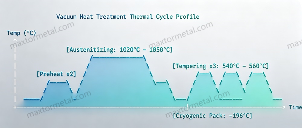
Để đạt được sự cân bằng thích hợp giữa khả năng chống mài mòn và độ bền cấu trúc, cần phải kiểm soát chính xác quá trình xử lý nhiệt. Chu trình tôi nhiệt tiêu chuẩn của Maxtor Metal dành cho dao cắt quay hợp kim cao cấp bao gồm:
Làm nóng sơ bộ hai giai đoạn: Các lưỡi dao được nung nóng từ từ đến 550℃ và sau đó đến 850℃ bên trong lò chân không cao (10-4 (mbar). Điều này giúp giảm thiểu sự chênh lệch ứng suất nhiệt và ngăn ngừa biến dạng trên toàn bộ hình dạng của cánh quạt.
Tôi hóa ở nhiệt độ cao: Nhiệt độ được nâng lên đến phạm vi austenit hóa đặc trưng của vật liệu (thường từ 1020℃ đến 1050℃ đối với hợp kim H13 cải tiến; lên đến 1180℃ đối với các biến thể PM) để hòa tan các nguyên tố hợp kim vào ma trận austenit ban đầu trong khi vẫn giữ được các ranh giới hạt mịn.
Làm nguội bằng khí có kiểm soát: Khí nitơ áp suất cao (4 bar đến 10 bar) được đẩy qua buồng để làm nguội nhanh các lưỡi dao, chuyển đổi austenit thành cấu trúc mactenxit cứng, không tôi luyện.
Tôi luyện ba lần dưới ngưỡng tới hạn: Để giảm ứng suất tôi luyện bên trong và tối ưu hóa độ dẻo dai, dao trải qua ít nhất ba chu kỳ ram riêng biệt ở nhiệt độ từ 540℃ đến 560℃. Quá trình này kích hoạt quá trình tôi cứng thứ cấp bằng cách kết tủa các cacbua hợp kim mịn và chuyển đổi austenit còn lại không ổn định thành mactenxit ram ổn định.
6.2 Cơ chế xử lý đông lạnh sâu
Xử lý bằng phương pháp đông lạnh sâu rất được khuyến nghị cho các hoạt động cắt xẻ hiệu suất cao. Ngay sau khi làm nguội bằng khí ban đầu, các lưỡi dao được làm lạnh dần bên trong một buồng đông lạnh chuyên dụng xuống đến -196℃ và giữ ở nhiệt độ này trong 24 đến 36 giờ.
Quá trình chuyển hóa Austenit hoàn toàn: Quá trình này thúc đẩy sự chuyển hóa austenit còn lại không ổn định thành mactenxit cứng, loại bỏ các điểm yếu về cấu trúc có thể gây ra sự biến dạng hoặc cong vênh trong quá trình hoạt động.
Kết tủa cacbua Eta (η): Quá trình xử lý bằng nhiệt độ cực thấp tạo ra các ứng suất vi cấu trúc, thúc đẩy sự kết tủa của các eta-cacbua siêu mịn, kích thước nano trong các giai đoạn tôi luyện tiếp theo. Điều này cải thiện đáng kể khả năng chống mài mòn vi mô của dụng cụ và giúp duy trì độ sắc bén của lưỡi cắt trong suốt quá trình sản xuất kéo dài.
6.3 Hồ sơ nitriding plasma kép
Đối với các ứng dụng cắt xẻ phức tạp, chẳng hạn như gia công thép silic mài mòn hoặc tấm thép carbon dày, lưỡi dao có thể được xử lý bằng phương pháp nitriding plasma kép. Được thực hiện trong buồng chân không sử dụng hỗn hợp khí hydro-nitơ ion hóa ở nhiệt độ dưới điểm tôi luyện (480℃ đến 500℃), quá trình này đưa nitơ nguyên tử vào mạng tinh thể bề mặt của thép.
Kiểm soát độ sâu trường hợp: Tạo ra vùng khuếch tán được kiểm soát chặt chẽ với độ sâu là 0,5 mm đến 0,10 mm.
Độ cứng từ bề mặt đến lõi: Quá trình này tạo ra một lớp vỏ bề mặt cứng có xếp hạng ở mức HV 900–1100, Trong khi đó, phần lõi vẫn duy trì độ bền cao và khả năng chống va đập (HRC 54–57). Thiết kế này đã giải quyết thành công thách thức kỹ thuật trong việc kết hợp khả năng chống mài mòn bên ngoài cao với khả năng hấp thụ va đập bên trong cao.
7.Hình học Dao & Kỹ thuật Lưỡi cắt
Độ chính xác của thao tác cắt rãnh quay phụ thuộc trực tiếp vào việc duy trì khe hở hình học và cấu hình cạnh chính xác:
7.1 Khe hở bên trục (Δx)
Khoảng cách ngang giữa mép cắt trên và mép cắt dưới là một thông số quan trọng.
Thép có độ dày tiêu chuẩn: Nằm giữa 8% và 12% là độ dày vật liệu.. Nếu khe hở quá nhỏ, các đường nứt trên và dưới sẽ cắt ngang nhau, gây ra hiện tượng cắt xé thứ cấp, ma sát vật liệu cao và mài mòn cạnh nhanh. Nếu khe hở quá lớn, vật liệu sẽ bị rách do kéo căng, tạo ra các gờ dày và nặng.
Thép siêu bền (UHSS): Khoảng hở bên phải phải được tăng lên. Từ 14% đến 18% là độ dày của tấm.. Vì các vật liệu có độ bền cao chống lại sự biến dạng dẻo, nên cần có khe hở rộng hơn để cho phép các vết nứt trượt lan truyền tự nhiên, ngăn ngừa các xung lực cực đoan có thể làm nứt hoặc vỡ lưỡi dao.
7.2 Độ chồng chéo xuyên tâm (h)o)
Độ sâu ăn khớp theo phương thẳng đứng của các lưỡi trên và dưới được điều chỉnh dựa trên độ dày và độ bền của vật liệu.
Vật liệu dạng dải mỏng (<0,5mm): Thông thường cần có sự chồng lấn dương nhỏ (Từ 2 mm đến 0,4 mm) để đảm bảo sự tách biệt hoàn toàn trên toàn bộ chiều rộng của vết cắt.
Tấm thép dày (≥3mm): Độ chồng lấp theo chiều dọc có thể được mở rộng lên đến 0 mm to ensure reliable material separation. This requires a highly rigid spindle system to prevent the knives from deflecting or backing off under load. For a full treatment of how overlap interacts with horizontal clearance across material families—including AHSS, aluminum, and stainless—see the rotary knife overlap settings guide.
7.3 Tạo hình cạnh và vát cạnh siêu nhỏ
Các cạnh sắc bén tiêu chuẩn, vuông góc 90° dễ bị sứt mẻ nhỏ khi chịu lực tác động mạnh. Để ngăn chặn điều này, Maxtor Metal sử dụng phương pháp xử lý cạnh chuyên biệt:
Mài siêu mịn: Lưỡi cắt được mài nhẹ bằng chất mài kim cương mịn để tạo ra bán kính đồng đều từ 5μm đến 15μm. Điều này giúp tăng cường độ chắc chắn cho lưỡi cắt, giảm sự tập trung ứng suất cục bộ mà không làm tăng sự hình thành bavia.
Vát mép nhỏ ở cạnh bên (vát mép bảo vệ 45°): Đối với các thao tác cắt xẻ tải nặng, một góc vát bảo vệ nhỏ 0,05mm*45° được mài vào góc cắt. Tính năng chuyển hướng này giúp hấp thụ lực tác động mạnh và ngăn ngừa hiện tượng sứt mẻ cạnh do sự biến đổi vật liệu hoặc rung động dây chuyền.
8.Quy trình Sản xuất & Kiểm tra Chất lượng
Mỗi lưỡi dao cắt xoay đều được sản xuất thông qua một chuỗi các thao tác chính xác để đảm bảo độ chính xác về kích thước và độ bền cấu trúc vượt trội:
8.1 Rèn vật liệu
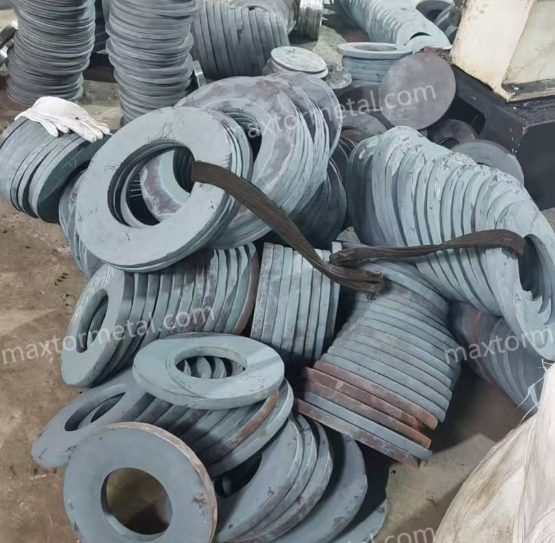
Rèn đa hướng: Các thỏi kim loại được rèn bằng máy ép thủy lực công suất lớn theo ba chiều, đạt tỷ lệ giảm rèn tối thiểu là 5:1. Điều này làm phá vỡ cấu trúc dạng nhánh cây và tinh chỉnh sự phân bố hạt.
8.2 Gia công thô và giảm ứng suất
Gia công tiện CNC: Các phôi rèn được gia công thô đến độ chính xác ±1,5mm so với kích thước cuối cùng, và các lỗ trung tâm được gia công trước.
Ủ nhiệt giảm ứng suất: Để loại bỏ ứng suất dư do quá trình rèn và gia công cơ khí nặng gây ra, các chi tiết được nung nóng đến 650℃, giữ trong 4 giờ và làm nguội từ từ trong lò. Điều này đảm bảo độ ổn định kích thước tuyệt vời trong quá trình xử lý nhiệt tiếp theo.
8.3 Xử lý nhiệt và xử lý đông lạnh (Vui lòng tham khảo Mục 6 để biết chi tiết đầy đủ về chu trình.)
Các phôi được tôi cứng bằng khí chân không và chu kỳ đông lạnh sâu đến -196℃, như được mô tả chi tiết trong Phần 6. Điều này giúp đạt được độ cứng mục tiêu đồng thời giảm thiểu ứng suất vật liệu bên trong.
8.4 Mài chính xác & Kiểm định đo lường
Mài bề mặt bằng máy quay: Bề mặt lưỡi dao được mài trên máy mài quay độ chính xác cao, trang bị trục chính thủy lực và hệ thống bù nhiệt tự động.
Mài lỗ: Lỗ tâm bên trong được mài với dung sai rất nhỏ (thường là H5, +0,011 / -0mm) để đảm bảo khớp chính xác với trục máy xẻ rãnh, giảm thiểu độ rơ hướng tâm.
Đánh bóng gương hai mặt: Các mặt bên của dao được xử lý bằng quy trình mài bóng tuần tự sử dụng dung dịch kim cương để đạt được độ nhám bề mặt Ra <0,2μm. Điều này loại bỏ các vết mài và tạo ra bề mặt bóng như gương, giúp giảm ma sát và ngăn ngừa sự bám dính vật liệu.
8.5 Quy trình kiểm tra chất lượng cuối cùng
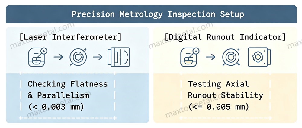
Kiểm tra kích thước: Độ dày và độ song song được kiểm tra bên trong phòng đo lường có điều hòa nhiệt độ (20℃±5℃) bằng cách sử dụng máy đo giao thoa laser và các thiết bị đo kỹ thuật số độ chính xác cao. Độ song song phải đo được dưới 0,003mm để đảm bảo khe hở cắt đồng đều.
Kiểm tra độ lệch trục: Dao sau khi hoàn thiện được gắn trên một trục chuẩn đã được chứng nhận và xoay dưới một thiết bị đo kỹ thuật số độ phân giải cao để xác minh rằng độ lệch trục vẫn ≤0,005mm.
Kiểm tra không phá hủy (NDT): Mỗi lưỡi dao đều trải qua quá trình kiểm tra bằng phương pháp từ tính (MPI) hoặc kiểm tra bằng chất thẩm thấu lỏng (LPI) trên toàn bộ cạnh cắt để xác nhận hoàn toàn không có vết nứt nhỏ hoặc vết cháy do mài.
9. Nghiên cứu tình huống / Case Studies thực tế
Nghiên cứu trường hợp 1: Khắc phục lỗi cạnh trong dây chuyền xẻ rãnh thép siêu cứng UHSS ngành ô tô
Dữ liệu sau đây đến từ dự án hỗ trợ của Maxtor Metal dành cho trung tâm dịch vụ thép ô tô, tên khách hàng đã được ẩn danh.
Hồ sơ khách hàng: Một trung tâm dịch vụ thép ô tô hàng đầu, chuyên xử lý các loại thép cường độ cao tiên tiến.
Thử thách: Nhà máy này sử dụng dao cắt quay D2/SKD11 thông thường để xẻ cuộn thép cường độ cao DP1180 dày 1,6mm. Lưỡi dao thường xuyên bị sứt mẻ nhỏ và gãy vỡ trên diện rộng dọc theo cạnh cắt, dẫn đến việc phải dừng dây chuyền để thay dao sau mỗi 12.000 mét sản lượng, gây ra hiệu suất thiết bị thấp và chi phí bảo trì cao.
Can thiệp kỹ thuật: Bộ phận kỹ thuật ứng dụng của Maxtor Metal đã phân tích ứng dụng và thay thế các lưỡi dao D2 dễ gãy bằng... Thép gia công nguội DC53 hàm lượng vanadi cao Lưỡi cưa được xử lý nhiệt đạt độ cứng HRC 60–62. Hệ thống mới bao gồm xử lý đông lạnh sâu để loại bỏ ứng suất vật liệu bên trong. Ngoài ra, khe hở cắt ngang đã được tăng từ tiêu chuẩn 10% lên đến... 16% của độ dày tấm để phù hợp với độ bền kéo cao của vật liệu.
Kết quả định lượng:
Kéo dài tuổi thọ dụng cụ: Khoảng cách cắt một đường thẳng tăng từ 12.000 mét lên hơn 25.000 mét trước khi cần phải mài lại.
Giảm thiểu sứt mẻ: Hiện tượng nứt vỡ lưỡi dao nghiêm trọng đã được loại bỏ hoàn toàn.
Tiết kiệm chi phí: Giảm chi phí dụng cụ hàng năm xuống 521 tấn và giảm số giờ ngừng hoạt động hàng tuần xuống 781 tấn. (Việc giảm thiểu các sự cố vỡ vụn nghiêm trọng đã loại bỏ tình trạng dừng dây chuyền sản xuất ngoài kế hoạch, điều này góp phần làm giảm thời gian ngừng hoạt động một cách không tương xứng so với việc kéo dài tuổi thọ dao.)
Nghiên cứu trường hợp 2: Khắc phục hiện tượng làm mềm cạnh và bavia trong quá trình xẻ rãnh thép silic
Dữ liệu sau đây đến từ dự án hỗ trợ của Maxtor Metal cho một nhà sản xuất tấm thép mỏng động cơ, tên khách hàng đã được ẩn danh.
Hồ sơ khách hàng: Nhà sản xuất máy biến áp điện hiệu suất cao và các tấm thép cán mỏng cho động cơ xe điện.
Thử thách: Nhà máy này đang xẻ các cuộn thép silic điện siêu mỏng, có độ mài mòn cao 0,35mm với tốc độ cao 250m/phút. Họ sử dụng lưỡi dao thép công cụ H13 tiêu chuẩn, loại lưỡi dao này bị mềm nhanh và mòn cạnh do nhiệt ma sát cao sinh ra trong quá trình hoạt động. Điều này dẫn đến hiện tượng gờ cạnh quá mức (>0,05mm), khiến các dải thép đã xẻ không đạt yêu cầu trong các bài kiểm tra cách điện.
Can thiệp kỹ thuật: Maxtor Metal đã triển khai một Vật liệu composite Mo+W được cải tiến H13 Thép dụng cụ được tôi cứng đến độ cứng HRC 58–60. Các lưỡi dao trải qua quy trình xử lý nhiệt chân không tiên tiến, tiếp theo là... Xử lý nitơ hóa bằng plasma sâu 0,8 mm Chu trình này tạo ra một lớp vỏ bề mặt cứng (HV 1000) bao phủ lõi cứng cáp. Bề mặt lưỡi dao cũng được đánh bóng gương đến độ nhẵn bề mặt Ra 0,15μm để giảm thiểu ma sát.
Kết quả định lượng:
Chất lượng cạnh: Các cạnh sắc nhọn được duy trì ổn định trong điều kiện 0,15 mm, Đã vượt qua tất cả các khâu kiểm tra chất lượng.
Khoảng thời gian mài lại: Khối lượng sản xuất liên tục giữa các lần mài lại lưỡi dao kéo dài từ 35.000 mét lên 210.000 mét. (Khoảng thời gian kéo dài phản ánh chế độ mài mòn đặc biệt mạnh của thép silic, trong đó xử lý bề mặt và lựa chọn hợp kim có tác động tổng hợp đến tuổi thọ dụng cụ.)
Giảm thiểu bụi: Các cạnh lưỡi dao được đánh bóng kỹ lưỡng giúp giảm thiểu ma sát, từ đó giảm đáng kể lượng bụi sắt trong không khí dọc theo đường cắt.
Các câu hỏi thường gặp (FAQ)
Câu 1: Tại sao chúng ta nên sử dụng thép công cụ H13 cải tiến thay vì thép D2/SKD11 thông thường để xẻ rãnh kim loại nặng?
A1: Thép D2/SKD11 thông thường có các cacbua crom lớn, giòn (M).7C37C3) lớn và giòn trong cấu trúc vi mô. Khi chịu lực nén và lực va đập chu kỳ cao trên các dây chuyền xẻ hiện đại, các hạt carbide lớn này đóng vai trò là điểm tập trung ứng suất, thường dẫn đến nứt đột ngột ở mép cắt hoặc hỏng lưỡi dao hoàn toàn. Thép H13 cải tiến sử dụng cấu trúc nền martensite dẻo dai và đồng nhất hơn, có khả năng chống nứt dưới tải trọng nặng, khiến chúng trở thành lựa chọn đáng tin cậy hơn nhiều cho các ứng dụng đòi hỏi khắt khe.
Câu 2: Việc bổ sung một lượng nhỏ vonfram (W) cải thiện hiệu suất của dao cắt H13 như thế nào?
A2: Vonfram kết hợp với cacbon trong quá trình xử lý nhiệt để tạo thành các hạt M mịn, cứng.6Các cacbua loại C. Các vi cacbua này làm tăng khả năng tôi cứng thứ cấp của vật liệu và duy trì độ cứng cao ở nhiệt độ cao, ngăn ngừa hiện tượng mềm lưỡi cắt do nhiệt ma sát trong quá trình xẻ tốc độ cao.
Câu 3: Niken (Ni) đóng vai trò gì trong các lưỡi cắt con lăn đường kính lớn?
A3: Niken làm tăng độ bền của ma trận thép thông qua quá trình tôi cứng dung dịch rắn, giúp tăng cường độ dẻo dai khi va đập ở nhiệt độ thấp và cải thiện các tính chất cơ học theo phương ngang. Đối với các loại dao có đường kính lớn (>400mm), độ dẻo dai bổ sung này giúp ngăn ngừa hiện tượng nứt dọc trục của dụng cụ dưới tác động của lực khóa ngang lớn.
Câu 4: Khi nào cần nâng cấp lên các loại thép luyện kim bột (PM) hiệu năng cao như ASP 23?
A4: Thép luyện kim bột (PM) rất được khuyến khích sử dụng cho các dây chuyền xẻ rãnh tự động, khối lượng lớn hoặc khi gia công các vật liệu mỏng, dễ mài mòn như thép silic điện, nơi chất lượng cạnh cắt là rất quan trọng. Quy trình luyện kim bột loại bỏ sự phân tách cacbua, tạo ra cấu trúc đồng nhất vượt trội, ngăn ngừa hiện tượng sứt mẻ nhỏ và kéo dài tuổi thọ dụng cụ từ 5 đến 10 lần so với thép thông thường.
Câu 5: Nguyên nhân chính gây ra hiện tượng mép cắt lượn sóng hoặc ngoằn ngoèo trên dải kim loại đã được xẻ rãnh là gì?
A5: Các cạnh lượn sóng thường do khe hở cắt không ổn định trong quá trình hoạt động, thường là do độ lệch trục vượt quá ≤0,005mm hoặc do sự thay đổi độ dày tích lũy trong cụm lưỡi dao và vòng đệm. Điều này khiến các lưỡi dao hơi rung lắc khi quay, làm cho khe hở ngang dịch chuyển động và gây ra hiện tượng cắt không đều.
Câu 6: Sự khác biệt về dung sai độ dày ảnh hưởng như thế nào đến hệ thống cắt nhiều dao?
A6: Trên trục xẻ rãnh có nhiều dao và miếng đệm, sai số độ dày riêng lẻ tích lũy dần trên toàn bộ cụm lắp ráp. Nếu dung sai của từng lưỡi dao không được giữ trong khoảng ±0,002mm đến ±0,005mm, tổng sai số tích lũy sẽ làm lệch dao trên và dao dưới, dẫn đến khe hở không nhất quán, chất lượng cạnh kém và làm tăng tốc độ mài mòn dụng cụ.
Câu 7: Tại sao thép siêu bền dùng trong ô tô lại cần khe hở cắt ngang rộng hơn?
A7: Vật liệu cường độ cao có điểm chảy cao và độ dẻo thấp. Nếu sử dụng khe hở tiêu chuẩn 10%, vật liệu sẽ không bị gãy gọn, gây ra sự tăng đột biến lớn về lực cắt, có thể nhanh chóng làm cùn hoặc sứt mẻ lưỡi dao. Tăng khe hở lên 14%–18% cho phép các vết nứt cắt gặp nhau một cách tự nhiên, đảm bảo sự tách rời gọn gàng với ít ứng suất hơn lên dụng cụ.
Câu 8: Xử lý đông lạnh sâu ở -196°C mang lại những lợi ích gì cho dao cắt quay?
A8: Xử lý bằng phương pháp đông lạnh chuyển hóa austenit còn lại không ổn định thành mactenxit tôi luyện ổn định và thúc đẩy sự kết tủa của các cacbua eta siêu mịn. Điều này cải thiện độ ổn định kích thước của dụng cụ, giảm ứng suất bên trong và đảm bảo khe hở cắt không bị thay đổi trong quá trình sản xuất tốc độ cao kéo dài.
Câu 9: Quá trình nitriding plasma trên lưỡi máy xẻ rãnh có mục đích gì, và liệu nó có làm cho dụng cụ trở nên giòn không?
A9: Quá trình nitriding plasma khuếch tán nitơ vào bề mặt lưỡi dao để tạo ra một lớp vỏ ngoài cứng, chống mài mòn (độ dày 0,05–0,10 mm, HV 900–1100) trong khi vẫn giữ được độ bền và khả năng chống va đập của lõi. Vì lớp nitriding mỏng và được hỗ trợ bởi một lõi chắc chắn, nó cải thiện đáng kể khả năng chống mài mòn mà không làm cho toàn bộ lưỡi dao trở nên giòn.
Câu 10: Bề mặt bên được đánh bóng như gương (Ra < 0,2 µm) giúp cải thiện hiệu suất cắt như thế nào?
A10: Bề mặt được đánh bóng như gương giúp loại bỏ các vết mài siêu nhỏ, nơi có thể hình thành vết nứt, giảm thiểu ma sát với dải kim loại đang chuyển động và giúp ngăn ngừa kim loại mềm bám dính vào dụng cụ. Nó cũng làm giảm lực cản ma sát và hạn chế sự tích tụ bụi sắt dọc theo dây chuyền sản xuất.
Câu 11: Có thể sử dụng lớp phủ DLC (carbon giống kim cương) khi xẻ thép cường độ cao không?
A11: Nhìn chung là không. Mặc dù lớp phủ DLC có hệ số ma sát cực thấp, nhưng chúng rất mỏng và cứng. Dưới lực nén cực mạnh cần thiết để cắt thép cường độ cao, ma trận thép bên dưới có thể bị biến dạng nhẹ, khiến lớp phủ DLC giòn bị nứt và bong tróc. DLC phù hợp nhất với các vật liệu mềm, dính như nhôm hoặc đồng.
Câu 12: Độ chồng chéo xuyên tâm theo phương thẳng đứng lý tưởng để xẻ tấm thép cacbon trung bình là bao nhiêu?
A12: Đối với các tấm thép cacbon tiêu chuẩn (dày từ 1,0mm đến 2,5mm), độ chồng chéo xuyên tâm theo chiều dọc tối ưu nằm trong khoảng từ 0,3 mm đến 0,6 mm. Độ sâu này giúp tạo ra vết cắt sạch mà không gây áp lực không cần thiết lên ổ trục chính của máy cắt.
Câu 13: Làm thế nào để ngăn ngừa hiện tượng sứt mẻ cạnh khi xẻ cuộn thép bị cong vênh hoặc không bằng phẳng?
A13: Các cuộn dây bị cong vênh tạo ra chuyển động ngang khó lường và lực tác động không đều khi chúng đi qua lưỡi dao. Trong những điều kiện này, thép công cụ H13 biến tính composite W+Ni được khuyến nghị, loại thép này cung cấp độ bền ma trận cao để hấp thụ các cú sốc đột ngột, kết hợp với một góc vát nhỏ bảo vệ trên cạnh cắt.
Câu 14: Tiêu chuẩn sản xuất không dung sai đối với kích thước cánh quạt không quan trọng là gì?
A14: Tất cả các kích thước không quan trọng hoặc không được ghi chú đều được sản xuất tuân thủ tiêu chuẩn ISO 2768-mK, đảm bảo chất lượng nhất quán trên mọi bộ phận.
Câu 15: Dao cắt quay cần được kiểm tra các vết nứt nhỏ bao lâu một lần trong quá trình bảo trì?
A15: Dao cần được làm sạch kỹ lưỡng và kiểm tra bằng phương pháp kiểm tra hạt từ tính (MPI) trong mỗi chu kỳ mài lại định kỳ. Việc mài trên các vết nứt nhỏ hiện có mà không loại bỏ hoàn toàn chúng có thể khiến các vết nứt sâu hơn, dẫn đến hỏng lưỡi dao đột ngột khi dụng cụ được đưa trở lại sử dụng.
Câu 16: Loại đá mài nào được khuyến nghị để mài lại lưỡi dao H13 đã được cải tiến?
A16: Nên sử dụng đá mài Cubic Boron Nitride (CBN) liên kết thủy tinh, kết hợp với chất làm mát tổng hợp hòa tan trong nước có lưu lượng cao. Tránh sử dụng đá mài oxit nhôm thông thường với tốc độ tiến dao lớn, vì nhiệt ma sát sinh ra có thể dễ dàng gây ra hiện tượng tôi luyện cục bộ và cháy mài trên thép dụng cụ.
Câu 17: Tại sao dung sai lỗ khoan nhỏ lại quan trọng đối với các dây chuyền xẻ rãnh tốc độ cao?
A17: Lỗ tâm thường được chế tạo với dung sai H5 để đảm bảo sự vừa khít và chính xác với trục máy cắt. Bất kỳ khe hở quá lớn nào giữa lỗ tâm và trục sẽ khiến dao quay lệch tâm một chút, dẫn đến những thay đổi tuần hoàn về độ chồng chéo xuyên tâm và tạo ra vết cắt không đều với các gờ không liên tục.
Câu 18: Nguyên nhân nào gây ra hiện tượng phát sinh nhiều bụi sắt xung quanh cụm máy xẻ rãnh?
A18: Lượng bụi sắt dư thừa thường do vật liệu cọ xát vào các cạnh lưỡi dao thô ráp (Ra >0,8μm) hoặc do khe hở quá nhỏ, làm mài mòn các cạnh đã cắt. Nâng cấp lên bề mặt lưỡi dao được đánh bóng như gương (Ra <0,2μm) sẽ giảm đáng kể ma sát này và hạn chế lượng bụi.
Câu 19: Làm thế nào để lựa chọn giữa thép nền (Caldie) và thép luyện kim bột (ASP 23)?
A19: Chọn thép ma trận nếu thách thức chính của bạn là hiện tượng nứt lưỡi hoặc các va đập cơ học mạnh từ các tấm thép dày và cứng. Chọn thép luyện kim bột nếu mục tiêu chính của bạn là khả năng chống mài mòn lâu dài và duy trì cạnh sắc bén, không có bavia trên các dây chuyền tốc độ cao.
Câu 20: Có thể sử dụng thép công cụ gia công nóng tiêu chuẩn cho các ứng dụng xẻ rãnh nguội không?
A20: Đúng vậy. Thép H13 tiêu chuẩn là loại thép dùng trong gia công nóng, nhưng độ bền va đập cao, độ dẻo tuyệt vời và khả năng chống mỏi nhiệt khiến nó trở thành vật liệu cơ bản đặc biệt cho các dây chuyền xẻ thép carbon cán nguội và cán nóng.
Đã được thẩm định kỹ thuật bởi: Chuyên gia luyện kim cao cấp tại Maxtor Metal.
Chọn Nam Kinh Metal công nghiệpcủa lưỡi cắt quay để sản xuất rạch kim loại hiệu quả và chính xác hơn, đồng thời tận hưởng sự đảm bảo về hiệu suất bền và chất lượng cao.
Tận hưởng sự tiện lợi của việc nhập khẩu liền mạch. Từ vận chuyển đến thông quan, chúng tôi xử lý toàn bộ quá trình. Tất cả những gì bạn cần làm là thanh toán VAT và chờ hàng đến công ty.
Giá Cả Cạnh Tranh
Chúng tôi đã chứng kiến lưỡi dao của mình xuất sắc trong vô số ứng dụng và sẵn sàng xử lý bất kỳ dự án nào bạn giao phó - mang lại độ chính xác, độ bền và mức giá cạnh tranh không đối thủ.
ODM & OEM Có Sẵn
Cho dù bạn cung cấp bản vẽ, phác thảo hay mẫu, chúng tôi đều có thể vẽ và sản xuất cho bạn. Chúng tôi cũng có khả năng hỗ trợ sửa đổi các thiết kế và thông số kỹ thuật hiện có để cải thiện hầu hết mọi ứng dụng dụng cụ công nghiệp. Vui lòng liên hệ với đội ngũ bán hàng chuyên trách của chúng tôi để thảo luận về các yêu cầu cụ thể của bạn.
Kiểm Soát Chất Lượng Nghiêm Ngặt
Một loạt các thử nghiệm và kiểm tra được thực hiện để kiểm soát chất lượng, bao gồm kiểm tra sản phẩm đầu tiên, kiểm tra nguyên vật liệu đầu vào và vật liệu được chứng nhận, kiểm tra chất lượng trong quá trình sản xuất, và kiểm tra chất lượng cuối cùng.
Mua Sắm Linh Hoạt, Hợp Tác Không Giới Hạn
Dù bạn là nhà nhập khẩu, nhà phân phối, nhà bán buôn hay người dùng cuối, chúng tôi đều chào đón bạn tham gia với MOQ tối thiểu, không rắc rối khi yêu cầu và tự do mua hàng hơn.
Giám Sát Nước Ngoài, Báo Cáo Tiến Độ Sản Xuất Thời Gian Thực
Trở thành người giám sát độc quyền của bạn, truyền tải thường xuyên mọi nút quan trọng trong dây chuyền sản xuất, dù ở xa đến đâu, tiến độ của sản phẩm sẽ được nắm bắt một cách tốt nhất có thể.








 English
  Spanish
 Italian
 French
 Portuguese
 Russian
 German
 Arabic
 Hindi
Hindi
 Vietnamese
 Indonesian
 Japanese
 Korean


