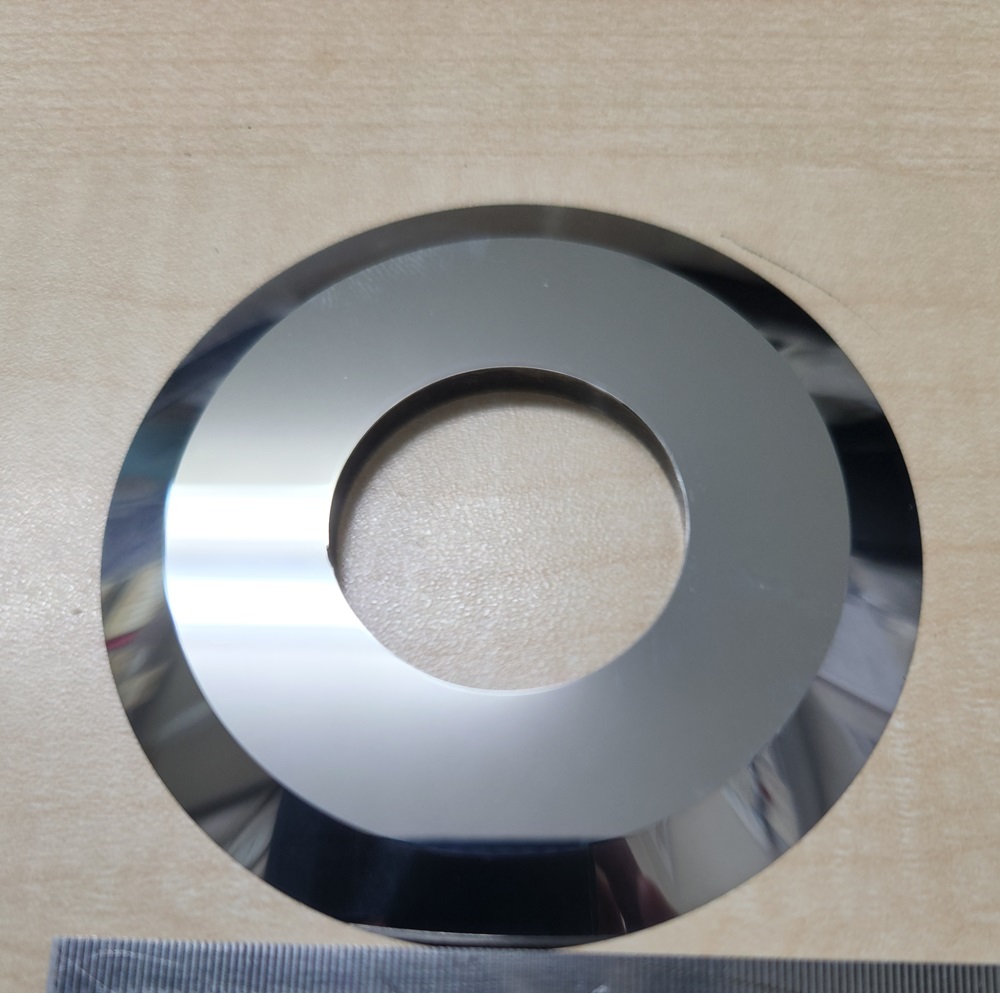
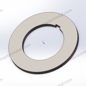
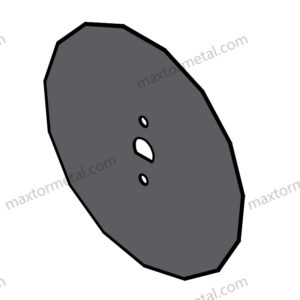
تستخدم سكاكين الشق الدائرية الدقيقة (المعروفة أيضًا باسم سكاكين الشق الدوارة أو شفرات الشق الدائرية) كينماتيكا دوران مستمرة بالاقتران مع سكين سفلية أنثى (القص بالمقص)، أو إعداد شفرة الحلاقة (الشق بالشفرة)، أو أسطوانة سندان صلبة (القص بالضغط/السحق) لتنفيذ عمليات الشق الطولي المستمر، أو التقطيع، أو إعادة اللف، أو التخديد للمواد المرنة المتحركة. تم تصميم هذه الأدوات الدوارة المتقدمة خصيصًا لآلات إعادة لف وتقطيع الورق وبكرات المواد عالية السعة، ومقاطع وخطوط تخديد الكرتون المضلع، وخطوط الشق الأوتوماتيكية لأقطاب بطاريات الليثيوم أيون.
1.1 OEM System Compatibility
This technical standard is engineered to meet or exceed the performance parameters of leading international slitting machinery manufacturers, including Kampf, Atlas, Goebel, Pasaban, Valmet, Dienes, Tidland, and ASHE.
1.2 Core Engineering Parameter Matrix
Engineering Parameter
Li-ion Electrode & Foil Classification
High-Speed Film, Tape & Paper
Heavy-Duty Silicon Steel & Slitting Lines
المواد الموصى بها
Sub-micron Tungsten Carbide (WC)
M2/M42 HSS, SK5, SK7, 1065 Carbon
DC53, LD, D2 (1.2379) / SKD11
Hardness Matrix
HRA 89 – 93
HRC 62 – 64 (HSS) / HRC 56 – 60
HRC 60 – 63 (DC53/LD)
Outer Diameter (OD) Range
40mm – 350mm
100mm – 680mm
80mm – 500mm
Inner Diameter (Bore) Tolerance
H7 / G6 Precision Slide Fit
H7 Standard Fit
H7 Precision Fit
تفاوت السماكة
± 0.001mm to ± 0.002mm
± 0.005mm
± 0.003mm
(التأرجح الجانبي)
< 0.005mm
< 0.015mm
< 0.010mm
Radial Runout (Out-of-Round)
≤0.010mm
≤0.020mm
≤0.015mm
Cutting Edge Roughness (Ra)
Ra < 0.4µm (Mirror Polish)
Ra < 0.8µm
Ra < 0.6µm
Side Face Roughness (Ra)
Ra < 0.8µm
Ra < 1.6µm
Ra < 1.2µm
Dimensional Standard
ISO 2768-mK
ISO 2768-mK
ISO 2768-mK
نظرة عامة على هندسة المنتج: كينماتيكا القص الدوار والتآكل التريبولوجي (الاحتكاكي)
In modern high-speed longitudinal slitting systems, the cutting edge of a circular blade experiences complex cyclic shear stress fields combined with high-velocity three-body abrasive wear. Because the tool rotates continuously, every discrete micro-segment along the blade’s circumference undergoes a rapid transition into and out of the material stress zone, rendering it highly susceptible to rolling contact fatigue.
2.1 Kinematics of the Shear Overlap Zone
In a synchronized shear slitting system (where the upper male blade overlaps and intersects with the lower female blade), the quality of the slit edge is governed by the configuration of the overlapping geometry:
Axial Side Clearance: For metallic foils, hard polymers, and silicon sheets, the physical horizontal gap between the upper and lower knives must be held strictly between 0.002mm and 0.01mm. If this clearance is exceeded, the substrate experiences localized bending and tensile elongation rather than true shear, generating catastrophic burrs. Conversely, an insufficient gap causes micro-rubbing, forcing an exponential increase in localized compressive stress and accelerating micro-chipping. For soft materials like paper and tissue, spring-loaded setups utilizing a constant pneumatic or mechanical axial preload are implemented to achieve a self-adjusting “zero-clearance” plane.
Overlap Depth: The vertical intersection depth of the male blade into the female channel must be calibrated between 0.5mm and 1.5mm. Excessive overlap depth increases the lateral friction contact area between the sides of the blades, transforming rotational kinetic energy into localized thermal energy, which softens the martensitic matrix of the cutting tip.
When a circular slitter runs at high linear velocities (e.g., 400–1200 m/min), any microscopic deviation in edge roughness (Ra) or structural homogeneity acts as a stress concentrator. As the blade dulls, the failure mode of the substrate shifts from clean shearing to compressive fracture. This transition creates micro-cracks in brittle coatings (such as battery cathode slurries) or fibers, discharging large quantities of microscopic debris and airborne dust. This dust can migrate onto the face of the blade, changing the friction coefficient (μ) and triggering a destructive thermal loop.
التطبيقات الصناعية: تحليل محدد حسب القطاع
3.1 Lithium-Ion Battery Electrode Slitting
Substrates: Copper foil, aluminum foil, and substrates double-coated with highly abrasive lithium iron phosphate (LFP) or nickel-manganese-cobalt (NMC) chemistries.
Engineering Requirements: The abrasive slurry contains hard ceramic-like particles that aggressively erode iron-based matrices. This application mandates Sub-micron Grain Tungsten Carbide (WC) with an HRA of 89–93. Thickness tolerances must be held to ±0.001mm to prevent axial tracking drift, which eliminates coating delamination and edge detachment on the current collector.
3.2 High-Velocity Polymer Film Conversion
Substrates: High-tensile BOPP, PET, and PI (Polyimide) films.
Machinery: Kampf, Goebel, and Atlas high-speed slitter rewinders.
Engineering Requirements: Thin polymer webs running at velocities exceeding 600 m/min are highly prone to static accumulation and frictional dragging. Thin-gauge circular blades made of SK5, SK7, or High-Carbon 1065 Spring Steel are specified. The cutting bevel must feature a mirror finish of Ra < 0.4µm to eliminate micro-grooves that pull on the polymer chains, preventing tensile tearing and static dust draw.
3.3 Silicon Steel & Transformer Core Slitting
Substrates: Oriented and non-oriented electrical silicon steel sheets with high silicon content.
Machinery: Heavy-duty rotary gang slitting lines.
Engineering Requirements: Silicon steel exerts extreme elastic deformation resistance, creating severe counter-reactive normal forces during shearing. Conventional D2/SKD11 blades frequently suffer from localized chipping under these cyclic shocks. DC53 or LD Steel (HRC 60–63) is mandatory here, leveraging its uniform carbide distribution to absorb high-impact mechanical stress.
3.4 Advanced Composite Prepreg Conversion
Substrates: Carbon fiber prepregs, fiberglass weaves, and resin-impregnated multi-layer textiles.
Machinery: Continuous-feed rotary cutter modules.
Engineering Requirements: Structural fibers possess extreme abrasive characteristics that blunt standard steel edges within hours. M2 or M42 High-Speed Steel (HSS) (HRC 62–64) enhanced with a physical vapor deposition (PVD) TiAlN coating is recommended. The coating acts as a thermal barrier, preserving the underlying edge hardness against continuous dry friction.
Substrates: Multi-layer aluminum-plastic laminates and sterile medical pouch films.
Machinery: Cleanroom-compliant slitting lines.
Engineering Requirements: To prevent web delamination and meet rigorous sanitary standards, blades must resist oxidation when exposed to humidity or sanitizing agents. High-chromium Martensitic Stainless Steels (420 or 440C) are selected and optimized to a hardness of HRC 48–56, achieving a stable balance between corrosion resistance and edge acuity.
Substrates: Heavy multi-wall corrugated board and linerboards.
Machinery: High-speed corrugated slitter scorers.
Engineering Requirements: The medium runs at high speeds and contains abrasive recycled fibers and silica particles. Tooling requires exceptional resistance to impact and abrasion. فولاذ عالي السرعة M2 is widely utilized, and the blades must be configured with an axial runout of <0.015mm to eliminate side-to-side wobble that causes crushed flutes or excess paper debris.
4.مشاكل الأعطال الشائعة والحلول الهندسية
4.1 Problem: Severe Slitting Dust Generation
Root Cause: Micro-nicks along the ground bevel or an uncalibrated axial side clearance force the blade to crush the substrate instead of shearing it. This mechanical crushing fractures fibers and coatings, generating significant debris.
Engineering Solution (Trade-Off Model): Specify a Super-Fine Mirror Polish on the blade bevels and faces, reducing the roughness to Ra < 0.1µm. While mirror polishing increases production cycle times and manufacturing costs by approximately 20%, it minimizes initial grinding micro-cracks and material dragging, reducing slitting dust by up to 80%.
Root Cause: High-hardness substrates (e.g., silicon steel, dense coatings) generate normal forces that exceed the fracture toughness of the blade’s alloy matrix. This issue is magnified by the presence of large, segregated primary carbides in standard cold-work steels like D2/SKD11.
Engineering Solution: Replace D2/SKD11 with DC53 or LD Tool Steel tempered to HRC 60–63. DC53 undergoes a refining process that yields a fine, uniform matrix with double the impact toughness of SKD11, preventing micro-chipping under cyclic loads.
Engineering Solution: Tighten the blade’s thickness tolerance to ±0.001mm and restrict the maximum allowable axial runout to <0.005mm via dynamic balancing and precision side grinding. Ensure the bore diameter follows an H7 or G6 slide-fit protocol to eliminate shaft eccentricity.
4.4 Problem: Adhesive Accumulation and “Galling” (Material Sticking)
Root Cause: When slitting pressure-sensitive adhesives, protective films, or soft aluminum foils, frictional heat causes adhesive polymers to melt or ductile metal to cold-weld onto the micro-roughness of the blade faces.
Engineering Solution: Implement targeted surface modification coatings. For adhesive-backed tapes, apply a Hydrophobic Fluoropolymer (PTFE/Teflon) Coating. For non-ferrous aluminum/copper slitting, apply a طلاء الكربون المشابه للماس (DLC). The extreme hardness and minimal friction coefficient of DLC stop material transfer at the atomic level. Note that coated blades cannot be conventionally resharpened on their faces; they require specialized edge-only grinding or recoating.
دليل هندسة المواد: الملامح الميتالورجية (الفيزيائية للفلزات)
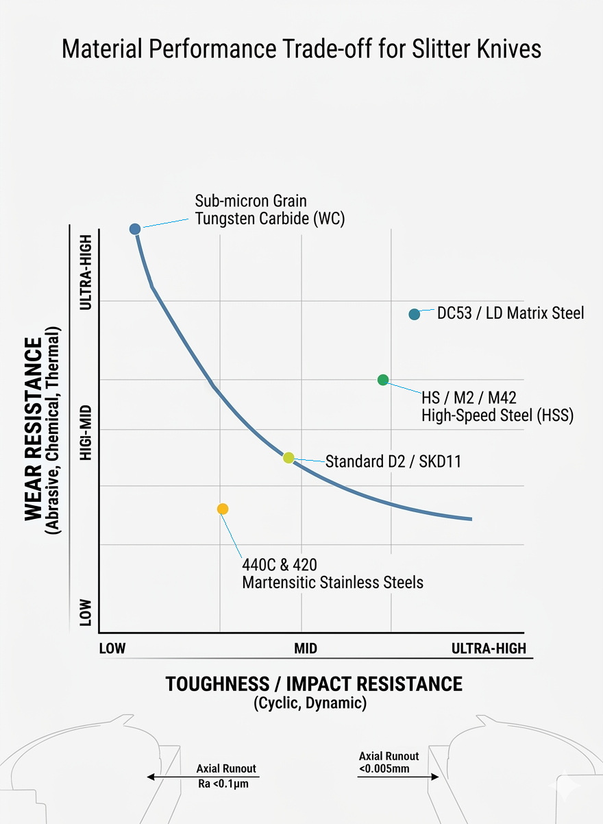
The rotational kinematics of circular cutting demand tool materials that offer balanced resistance to rolling contact fatigue, compression, and abrasive wear.
Sub-micron Grain Tungsten Carbide (WC)
Metallurgical Matrix: Composed of ultra-fine sub-micron tungsten carbide hard phases bonded within a high-toughness cobalt (Co) matrix, with an average grain diameter of ≤0.6μ m.
Mechanical Profile: Provides exceptional hardness (HRA 89–93) and excellent resistance to abrasive slurry wear. However, it exhibits low bending strength and high brittleness; any metal-to-metal collision or foreign body impact will cause catastrophic fracturing.
DC53 / LD Matrix Steel
Metallurgical Matrix: A cold-work tool steel designed to eliminate the coarse, segregated primary chromium carbides characteristic of traditional D2/SKD11 steels.
Mechanical Profile: Achieves a heat-treated hardness of HRC 60–63. Its uniform microstructure yields double the impact toughness of SKD11, making it highly effective at preventing edge chipping when shearing high-tensile metals or thick polymers.
M2 / M42 High-Speed Steel (HSS)
Metallurgical Matrix: Heavily alloyed with Tungsten (W), Molybdenum (Mo), Chromium (Cr), and Vanadium (V) to form a dense distribution of thermally stable M6C and MC secondary carbides.
Mechanical Profile: Possesses high “Red Hardness” (retaining structural integrity up to 500°C) and excellent impact resistance. This makes it suitable for high-speed corrugated paper and composite conversion lines experiencing high-frequency friction.
440C & 420 Martensitic Stainless Steels
Metallurgical Matrix: Contains 12%–18% Chromium, which forms a passive chromium oxide film upon thermal hardening, embedded within a tempered martensitic matrix.
Mechanical Profile: Delivers a controlled hardness of HRC 48–56. It provides reliable protection against oxidation, pitting, and chemical exposure in humid or sterile food and pharmaceutical converting facilities.
المعالجة الحرارية والصلادة: منطق التعديل الحراري
The dimensional stability and edge retention of a circular blade depend heavily on its internal crystalline matrix. Thermal processing errors will cause axial warping and distortion under high-speed rotation.
6.1 Multi-Stage Vacuum Gas Quenching & Tempering
To prevent decarburization and surface oxidation, all steel slitter blanks undergo heat treatment inside a high-vacuum furnace operating at 10-3mbar. The blades are brought up through multi-stage preheating cycles to eliminate thermal gradients and prevent warping in thin-disc configurations. They are austenitized at 1020℃-1100℃(depending on the alloy grade) and quenched using high-pressure, high-purity nitrogen gas (6–10 bar). This is followed by three distinct tempering cycles to minimize residual internal stresses.
6.2 Cryogenic Transformation for Ultra-Precise Tolerances
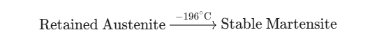
For high-specification applications requiring sub-micron thickness tolerances (±0.001mm), a comprehensive Deep Cryogenic Treatment (Sub-Zero Liquid Nitrogen Soaking at -196°C) is performed:
Cryogenic processing drives the near-total conversion of unstable retained austenite into hardened martensite while precipitating ultra-fine secondary \eta-carbides throughout the matrix. This provides two key engineering benefits:
Elimination of Thermal Distortion: It prevents microscopic dimensional shift or axial bowing when the blade warms up under high-speed friction, ensuring a true cutting line.
Extended Wear Life: Field performance data indicates that cryogenically treated slitter blades exhibit a 30% or greater increase in wear resistance compared to conventionally treated alternatives.
7.هندسة شكل الشفرة وحافة القطع
The geometric tolerances of a circular slitter directly impact its rotational stability. Even minor side-to-side variations can cause wavy cut paths or premature tool failure.
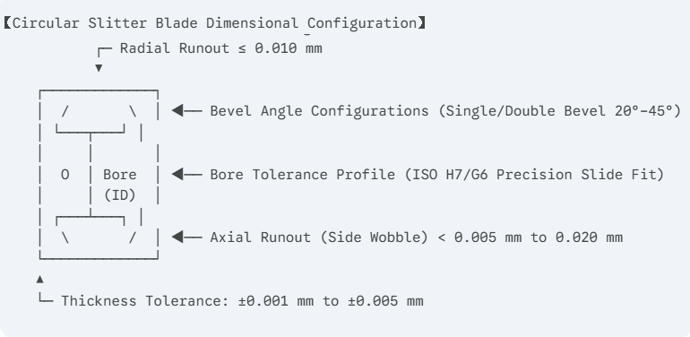
7.1 Geometric Tolerance Chains
Bore-to-Shaft Concentricity: The central bore must be finished to an ISO H7 or G6 tolerance class to establish a precise slide fit with the slitter shaft. A bore clearance error as small as 0.01mm introduces an eccentric rotation axis, magnifying the Radial Runout and causing uneven material engagement.
Axial Runout Control: Side wobble must be restricted to <0.005mm for high-precision applications and <0.020mm for general converting. Exceeding these limits causes the overlapping faces of the male and female knives to impact each other during rotation, generating micro-shocks that cause chipping, accelerated face wear, and ragged edges.
Blades can be ground to a Single Bevel, Double Bevel, or Compound Bevel configuration, with included angles ranging from 20° to 45°:
Acute Bevel Angles (20° – 25°): Minimize the specific cutting force (kج) and drag resistance. This configuration is suitable for delicate, non-woven materials and ultra-thin packaging films, though it offers lower structural edge strength.
Obtuse Bevel Angles (35° – 45°): Provide a robust wedge profile with excellent mechanical backing. This is the standard configuration for processing tough substrates like silicon steel or abrasive mineral-filled sheets.
8.عملية التصنيع وفحص الجودة
Ingot Metallurgy & Consolidation: High-purity tool steel blanks are processed via Electro-Slag Remelting (ESR). For tungsten carbide, blanks are produced using Hot Isostatic Pressing (HIP) vacuum sintering to ensure a void-free, homogeneous structure.
CNC Core Machining: Precision turning of the central bore, drive notches, and locating faces to satisfy H7/G6 specifications.
Vacuum Thermal Modification & Deep Cryogenics: Hardening and subsequent sub-zero processing at -196°C to eliminate residual stresses.
Double-Disc Parallel Grinding: Multi-pass grinding under constant-temperature coolant lubrication to achieve flat, parallel sides with a thickness tolerance down to ±0.001mm.
Rotary Edge Bevel Grinding: Using dedicated high-rigidity grinding centers equipped with vitrified diamond wheels to profile the cutting edge to a finish of Ra < 0.4µm.
Quality Control Protocol:
Laser Interferometric Axial Runout Verification: Every high-precision blade is evaluated across its entire circumference. Side wobble is mapped and documented to confirm compliance with the <0.005mm internal threshold.
Surface Profilometry: Direct stylus measurement of the bevel’s surface finish (Ra).
Multi-Point Rockwell Hardness Mapping: Verifies that the hardness variance across the blade face does not exceed 0.5 HRC.
دراسات الحالة: الأداء الميداني الموثق
Case Study A: Lithium-Ion Battery Anode Slitting (Graphite-Coated Copper Foil)
Client Profile: A tier-one manufacturer of electric vehicle battery cells.
Initial Problem: The client was utilizing commercial-grade carbide rotary blades with a thickness tolerance of ±0.005mm and an edge roughness of Ra 0.8µm. Abrasive graphite particles caused material to adhere to the blade faces, limiting linear slitting speeds to 200 m/min. Micro-chipping occurred after 15 hours of operation, causing coating delamination and micro-burrs along the copper foil.
Engineering Intervention: Installed Sub-micron Tungsten Carbide Blades featuring a mirror polish of Ra < 0.1µm and a thickness tolerance held strictly to ±0.001mm.
Quantifiable Outcomes: Face adhesion was eliminated, allowing production speeds to be increased from 200 m/min to 550 m/min (a 175% increase in throughput). Individual blade service life rose from 15 hours to 120 hours between grinds, while micro-dust emissions fell by 88%.
Case Study B: High-Frequency Electrical Silicon Steel Gang Slitting Line
Client Profile: A steel service center specializing in transformer core laminations.
Initial Problem: The line used standard D2 (SKD11) circular blades (HRC 58–60) to slit 0.35mm thick grain-oriented silicon steel. The material’s high deformation resistance caused micro-fractures along the blade edges within 32 operating hours. This dulling produced edge burrs exceeding 0.08mm, which caused electromagnetic performance loss in the final transformer stacks.
Engineering Intervention: Transitioned to DC53 Matrix Steel Circular Blades subjected to vacuum quenching and deep cryogenic stabilization, achieving a uniform hardness of HRC 61–62.
Quantifiable Outcomes: The high fracture toughness of DC53 eliminated micro-chipping. The required resharpening interval was extended from 32 hours to 145 hours of continuous operation. Slit edge burrs were maintained below ≤0.015mm, reducing sheet rejection rates by 92%.
الأسئلة الشائعة: مرجع الهندسة والمشتريات
لماذا يُعد تفاوت السُمك أمرًا بالغ الأهمية عند إعداد نظام الشق المتعدد (gang-slitting) باستخدام حلقات التباعد (Spacer collars)؟
في تجميعة الشق المتعدد متعددة الشفرات، تتراكم تفاوتات السُمك الفردية عبر عمود الدوران. يمكن أن يؤدي تباين طفيف قدره ±0.01 مم لكل شفرة إلى إزاحة محور مجمعة تزيد عن 0.1 مم عبر إعداد مكون من 10 شفرات. تغير هذه الإزاحة الخلوص الجانبي الأفقي المعاير بين الحواف العلوية والسفلية، مما يتسبب في حدوث رايش (burrs) شديد أو تصادم الشفرات. إن تضييق التفاوتات الفردية إلى ±0.001 مم يقلل من هذا الخطأ التراكمي إلى الحد الأدنى.
ما الذي يميز البنية الميتالورجية للكربيدات في فولاذ DC53 عن فولاذ D2/SKD11 التقليدي؟
يحتوي فولاذ الأدوات D2 التقليدي على كربيدات كروم أولية كبيرة ومنفصلة (غالبًا ما يكون قطرها ≥20 ميكرومتر) تشكل شبكات هشة أثناء التجمد. يمكن أن تتشقق هذه الكربيدات الكبيرة تحت تأثير القوى العمودية العالية الناتجة عند شق فولاذ السيليكون (صلب السليكون). يخضع فولاذ DC53 لتعديل كيميائي دقيق وروتين معالجة يستبدل هذه التكتلات الكبيرة بكربيدات ثانوية ناعمة ومشتتة بشكل متساوٍ، مما يضاعف متانة الصدمات (toughness) للمادة.
يعاني خط الشق لدينا من تموج الشريط المتحرك (web weaving) وحواف ممزقة في فيلم BOPP عند سرعة 800 متر/دقيقة. ما الذي يجب علينا التحقق منه أولاً؟
ابدأ بفحص الارتجاج المحوري (التأرجح الجانبي) للشفرات العلوية باستخدام مؤشر قرصي عالي الدقة أو مقياس ليزر. إذا تجاوز الارتجاج 0.020 مم، فسوف تتأرجح الشفرة أفقيًا عبر مسار الشريط، مما يتسبب في تموج ملف الحافة. بعد ذلك، تحقق من أن خشونة الحافة أقل من Ra 0.4 ميكرومتر؛ إذ يمكن للحواف الأكثر خشونة أن تشتبك مع سلاسل البوليمر عند السرعات العالية، مما يتسبب في تمزق موضعي.
هل يمكن إعادة شحذ سكاكين الشق الدائرية المصنوعة من كربيد التنجستن بنجاح؟ وما هي القيود الرئيسية؟
نعم، يمكن إعادة شحذ السكاكين الدائرية المصنوعة من الكربيد (المعدن الصلد)، ولكنها تتطلب آلة تجليخ عالية الصلابة مجهزة بحجر تجليخ ماسي برابط راتنجي ونظام تبريد غامر مستمر وعالي التدفق. يؤدي التجليخ الجاف أو غير المستقر إلى خلق تدرجات حرارية موضعية شديدة تسبب شقوقًا دقيقة على طول مصفوفة الكربيد الهشة، مما يؤدي إلى فشل الحافة المبكر على خط الإنتاج.
يقضي الصقل المرآتي على حواف وأثلام التجليخ المجهرية الموجودة على حواف الأدوات القياسية. يقلل هذا السطح الأملس من معامل الاحتكاك (μ) بين وجه الشفرة ومادة الشريط المتحرك. وبدون وجود خشونة دقيقة تخدش المادة أو تسحبها، يظل الفصل الميكانيكي عبارة عن قص نظيف، مما يقلل من انبعاثات الغبار.
ما هو نظام "التحميل المسبق الدقيق" (micro-preload) المحمل بنوابض، ومتى يجب تطبيقه؟
بالنسبة للأشرطة المتحركة الرقيقة والمرنة مثل المناديل الورقية (tissue)، أو ورق السجائر، أو أفلام التغليف الرقيقة، قد يكون من الصعب ضبط خلوص جانبي مادي ثابت باستخدام فواصل صلبة. يستخدم نظام التحميل المسبق الدقيق آلية هوائية أو نابضًا معايرًا لتطبيق قوة جانبية ثابتة، مما يحافظ على مستوي قص خلوص صفري يمنع المادة الرقيقة من الانطواء بين الشفرات.
هل الموازنة الديناميكية ضرورية لجميع شفرات الشق الدائرية؟
تصبح الموازنة الديناميكية ضرورية عندما تتجاوز سرعة خط الشق 1000 متر/دقيقة. عند هذه السرعات، فإن أي عدم تماثل طفيف في الكتلة على طول محيط الشفرة يولد اهتزازات طرد مركزي عالية التردد بشكل كبير. يؤدي هذا الاهتزاز إلى تدهور استقرار مستوى القص، مما يسرع من تأكل الحافة ويتسبب في جودة شق غير متناسقة.
متى يجب أن أختار طلاء التفلون بدلاً من طلاء DLC لتطبيق الشق؟
اختر طلاء الفلوروبوليمر (التفلون) عند شق المواد اللاصقة الحساسة للضغط، أو أشرطة النقل، أو الضمادات الطبية، لأنه يوفر مقاومة ممتازة للالتصاق اللاصق. ومع ذلك، فإن التفلون يتميز بصلابة ميكانيكية منخفضة. بالنسبة لشق المعادن غير الحديدية مثل رقائق الألومنيوم أو النحاس، اختر طلاء الكربون الشبيه بالماس (DLC)؛ حيث تقاوم صلابته العالية التآكل الكاشط وتمنع انتقال المعادن واللحام البارد.
لماذا يُفضل صلب السرعات العالية M2/M42 على كربيد التنجستن في عمليات تحويل الورق ذات الحجم الكبير؟
تواجه خطوط تحويل الورق عالية السرعة بشكل متكرر تقلبات في شد الشريط، والوصلات (splices)، والملوثات الخارجية العرضية. في حين أن كربيد التنجستن يوفر مقاومة ممتازة للتآكل، فإن متانة الكسر المنخفضة تجعله عرضة للتحطم تحت صدمات الشد المفاجئة. يوفر صلب السرعات العالية (HSS) M2/M42 صلابة حمراء عالية إلى جانب متانة تأثير ممتازة، مما يسمح له بتحمل الصدمات الميكانيكية دون فشل هيكلي.
كيف يؤدي التركيز العالي للأوستنيت المتبقي إلى تدهور الأداء الميداني لسكين الشق الدقيق؟
الأوستنيت المتبقي هو طور بلوري غير مستقر وعالي الطاقة في درجة حرارة الغرفة. وتحت تأثير الإجهاد الميكانيكي الدوري وحرارة الاحتكاك المتولدة أثناء الشق، يمكن أن يتحول إلى مارتنسيت. ويصاحب هذا التحول تمدد حجمي موضعي، يمكن أن يغير المقطع المستوي للشفرة، مما يؤدي إلى زيادة الارتجاج المحوري وفقدان دقة القص.
لماذا تظهر شفرات الفولاذ المقاوم للصدأ 440C تآكلاً متسارعاً عند شق المواد المركبة الكثيفة؟
إن 440C هو فولاذ مقاوم للصدأ مارتن سيتي صُمم أساساً لمقاومة التآكل الكيميائي (الصدأ). وللحفاظ على خصائصه المقاومة للصدأ، تظل نسبة كبيرة من الكروم داخل مصفوفة المحلول الصلب، مما يترك كمية أقل من الكربون الحر وعناصر السباكة لتشكيل كربيدات الفاناديوم أو الموليبرنيوم الصلبة. وبناءً على ذلك، فإن ذروة مقاومته للتآكل الكاشط تكون أقل من فولاذ الأدوات المتخصص مثل DC53 أو صلب السرعات العالية (HSS) M2.
ما هي عواقب تجاوز تفاوت استدارة التجويف الداخلي في تجميع عمود سكين الشق؟
إذا تجاوز تفاوت التجويف الداخلي مواصفة H7/G6، ستستقر الشفرة بشكل فضفاض على عمود الشق، مما يخلق محور دوران غير مركزي (مائل). يؤدي هذا اللامركزية إلى ارتفاع الارتجاج الشعاعي (النبض الدائري)، مما يعني أن الشفرة ستدخل في المادة بأعماق متغيرة طوال دورانها، مما يتسبب في تآكل دوري وأعماق قص غير متسقة.
ما هي الخصائص التي تجعل Prepregs الألياف الزجاجية كاشطة للغاية لحواف الأدوات؟
تتكون الألياف الزجاجية من خيوط السيليكا غير المتبلورة ذات الصلابة الفيزيائية العالية. وأثناء الشق، تعمل هذه الخيوط كعوامل كاشطة دقيقة ضد حافة القص. إذا كانت مادة الشفرة تفتقر إلى حجم أو صلابة كافية من الكربيدات الثانوية، فإن الألياف المارة سوف تأكل المصفوفة بسرعة، مما يؤدي إلى تدوير مقطع الحافة (فقدان حدتها).
ما هو حد الصيانة الموصى به لجدولة عمليات شحذ الشفرات أثناء فترات التوقف؟
يجب جدولة الشفرات لإعادة الشحذ عندما يتآكل نصف قطر الحافة الدقيقةβ(rβ)ليصبح بين 0,1 مم و0,2 مم، أو عندما يتجاوز ارتفاع الرايش (البروز) في المنتج حدود الجودة. إن الانتظار حتى حدوث تكسر كبير في الحافة أو تبلد شديد يتطلب إزالة كمية كبيرة من المواد أثناء إعادة التجليخ، مما يقلل من العدد الإجمالي لدورات الشحذ ويخفض العمر الافتراضي الإجمالي للأداة بنسبة تصل إلى 60%.
ما هو الفرق الرئيسي بين تكوين الشطبة الأحادية (Single Bevel) والتكوين المركب (Compound Bevel)؟ a single bevel and a compound bevelconfiguration?
تتميز الشطبة الأحادية بمستوى مائل مستمر واحد يؤدي إلى حافة القطع، مما يمنحها مقطعاً حاداً ومقاومة قطع منخفضة. أما الشطبة المركبة، فتقوم بإدخال شطبة دقيقة ثانوية (micro-bevel) عند طرف الحافة تماماً. تعمل هذه الشطبة الدقيقة على تقوية حافة القطع ضد القوى العمودية العالية وضد التكسر، مما يطيل عمر الأداة في التطبيقات الشاقة مع زيادة طفيفة فقط في مقاومة القطع.
استمتع براحة الاستيراد السلس. من النقل إلى التخليص الجمركي، نحن نتعامل مع العملية بأكملها. كل ما عليك فعله هو دفع ضريبة القيمة المضافة وانتظار وصول بضائعك.
أسعار تنافسية
لقد رأينا شفراتنا تُستخدم في عدد لا يحصى من التطبيقات وهي جاهزة للتعامل مع أي مشروع تطرحه علينا - حيث توفر الدقة والمتانة والتسعير التنافسي الذي لا مثيل له.
سواء قدمت رسومات أو مسودات أو عينات، نحن قادرون على الرسم والتصنيع لك. لدينا أيضًا القدرة على المساعدة في تعديل التصميمات والمواصفات الحالية لتحسين أي تطبيق للأدوات الصناعية تقريبًا. يرجى الاتصال بفريق المبيعات المخصص لدينا لمناقشة متطلباتك المحددة.
مراقبة الجودة
يتم إجراء سلسلة من الاختبارات والفحوصات للتحكم في الجودة، بما في ذلك فحص العينة الأولى، فحص المواد الواردة والمواد المعتمدة، فحص الجودة أثناء العملية، وفحص الجودة النهائي.
شراء مرن، تعاون غير محدود
سواء كنت مستوردًا أو موزعًا أو تاجر جملة أو مستخدمًا نهائيًا، نرحب بك للانضمام إلينا بحد أدنى للكمية المطلوبة (MOQ)، وبدون متاعب للاستفسار، ومزيد من الحرية في الشراء.
مراقبة خارجية، تقرير في الوقت الفعلي عن تقدم الإنتاج
كن مراقبك الحصري، ونقل منتظم لكل نقطة مهمة في خط الإنتاج، بغض النظر عن المسافة، للسيطرة على تقدم المنتج قدر الإمكان.