

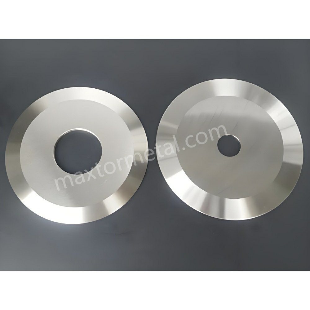
يحدث القطع الثعباني (والذي يُسمى أيضاً انحراف أو جرف خط التقطيع) عندما لا تستطيع الحافة المقطوعة الحفاظ على مسار مستقيم ومكرر: حيث "تتحرك" المسارات أو تتذبذب أو تنزاح تدريجياً، مما يؤدي إلى عدم تراكب طبقات اللفافة الملتفة في المركز. تعامل مع هذه المشكلة باعتبارها خللاً في استقرار نظام التقطيع واللف بأكمله—وليس كعيب ناتج عن عنصر واحد فقط.
تعكس قائمة التحقق هذه الطريقة التي تعتمدها معظم فرق الصيانة والعمليات لمعالجة المشكلة في الموقع. وهي تستند إلى تسلسل التشخيص الذي يستخدمه فريق الهندسة الميدانية في Maxtor Metal عند استكشاف الأخطاء وإصلاحها لسبب تدهور استقرار القطع عند السرعات العالية رغم ظهوره بشكل ممتاز أثناء الإعداد.
أهم النقاط الرئيسيةإذا كانت مسارات الثعبان تتغير بتغير السرعة أو بناء التدحرج أو موقع المسار، فابدأ بعزلها. من أين تأتي القوة الجانبية (قوى السكين مقابل ميكانيكا الشبكة مقابل الهواء/الكهرباء الساكنة) قبل أن تبدأ في "تدوير المقابض".“
يُعد هذا النهج التشخيصي القائم على الأنظمة هو الإطار الذي يطبقه فريق هندسة التطبيقات في Maxtor Metal عند تقديم الدعم للعملاء في خطوط تقطيع الأغشية والأقمشة غير المنسوجة، حيث استمر انحراف المسارات malgré المحاولات القائمة على تعديل متغَيّر واحد.
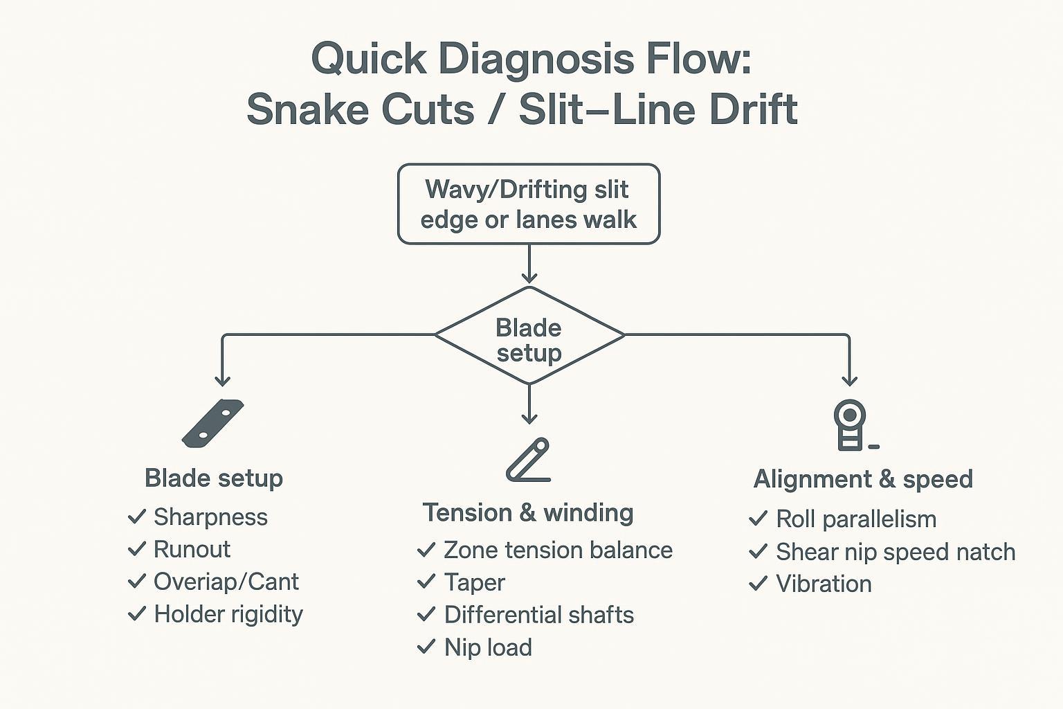
مسار التشخيص السريع
متى يجب الاشتباه في وجود مشاكل في الشفرة؟
- المشكلة هي خاص بالمسار (انجراف مسار أو مسارين بينما يحافظ الجيران على مواقعهم).
- بداية الانجراف مباشرة عند نقطة الشق, ، حتى عند السرعات المنخفضة.
- لقد قمت مؤخرًا بتغيير السكاكين أو الفواصل أو الحوامل أو نقل مجموعة السكاكين.
- يتميز الانحراف بطابع متكرر "مرة واحدة لكل دورة" (غالباً ما يرتبط بالخروج عن المسار أو بمقعد غير مستقيم).
فحوصات سريعة:
- تحقق من نظافة مجموعة السكاكين (لا يوجد غشاء عالق، أو مادة لاصقة، أو نتوءات على الأسطح).
- فحص انحراف مؤشر القياس على أسطح المحور/السكين في الممرات التي تنحرف.
- تأكد من أن التداخل/التعشيق والميل/الاتجاه ضمن النطاق المتوقع لطريقة القطع.
متى يُشتبه في وجود شد/لف
- يزداد الانجراف سوءًا مع يزداد قطر اللفة.
- ينتقل العيب من حارة إلى أخرى مع الموقع الأساسي أو تغييرات البرج.
- هل ترى التلسكوب, ، أو الحواف غير المحكمة، أو اختلاف الصلابة من حارة إلى أخرى.
- يتحسن الانجراف فورًا عندما يقلل أو تغيير نقاط ضبط التوتر.
فحوصات سريعة:
- قارن توترات مناطق فك اللف/منتصف الشبكة/إعادة اللف (الفعلية مقابل نقطة الضبط).
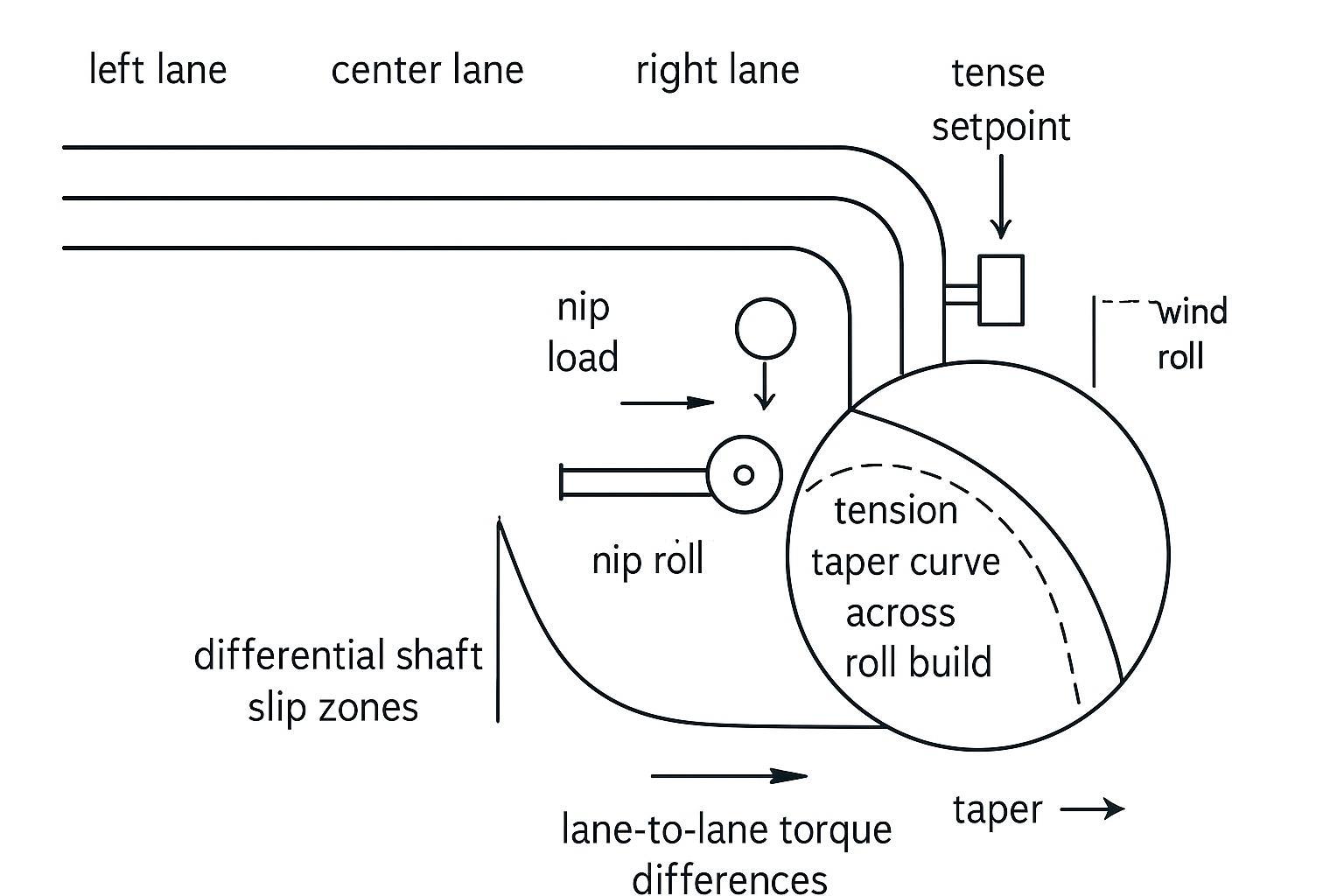
- تحقق من سلوك الشد المخروطي عبر عملية بناء اللفة.
- تأكد من أن انزلاق عمود التروس التفاضلية يعمل بشكل صحيح في كل حارة على حدة (لا توجد عناصر عالقة).
متى يجب الاشتباه في محاذاة/سرعة المحرك؟
- يزداد الانحراف سوءًا بعد الصيانة أو استبدال المحامل أو التعرض لصدمة/حمل زائد.
- تتتبع الشبكة مسار التيار بشكل جيد، ثم تتغير بعد لفة أو انقباض معين.
- تسمع/تشعر بالاهتزاز، أو ترى علامات النمط، أو تلاحظ تذبذب دليل الحافة.
فحوصات سريعة:
- توازي اللف وتوازن الضغط؛ ابحث عن أي انحراف واضح أو تآكل غير متساوٍ.
- مطابقة السرعة عند نقطة القص (سرعة السكين مقابل سرعة الشريط).
- صحة المحامل والاهتزاز (درجة الحرارة، الضوضاء، الطيف إن وجد).
قطع الثعبان مصفوفة السبب الجذري
استخدم هذا الجدول كمرجع سريع للفرز قبل تعديل أي إعدادات.
| نمط الأعراض | النظام الفرعي الأكثر احتمالاً | التحقق الأول |
|---|---|---|
| الانحراف الخاص بكل مسار، يبدأ من نقطة التقاطع، ويحدث عند السرعات المنخفضة | الشفرة / الحامل | احسب نسبة الانعكاس الكلي عند أسطح الأشجار والسكاكين في الممرات المتأثرة؛ قارنها بالممرات المستقرة |
| يزداد الانزلاق سوءًا مع ازدياد الميلان؛ ويتحسن عند انخفاض السرعة | لفّ الشد / اللف التفاضلي | الشد الفعلي مقابل الشد المحدد في كل منطقة؛ عزم انزلاق العمود التفاضلي |
| ظهر الانحراف بعد الصيانة أو عطل ميكانيكي | المحاذاة / المحمل | توازي البكرات؛ درجة حرارة المحمل وطيف الاهتزاز |
| يختلف الانحراف باختلاف موقع اللفة الأصلية أو موقع المسار (الحافة مقابل المركز) | شكل المادة / المقياس | تباين سماكة الشبكة؛ ارتباط صلابة كل مسار بموضع الأسطوانة الأصلية |
| يزداد الانزلاق سوءًا مع زيادة السرعة، ويتحسن عند زيادة ضغط التوجيه. | سحب الهواء / ثابت | اختبار تخفيض السرعة؛ فحص استمرارية خرج المؤين والتأريض |
ضبط الشفرة والتفاوتات المسموح بها
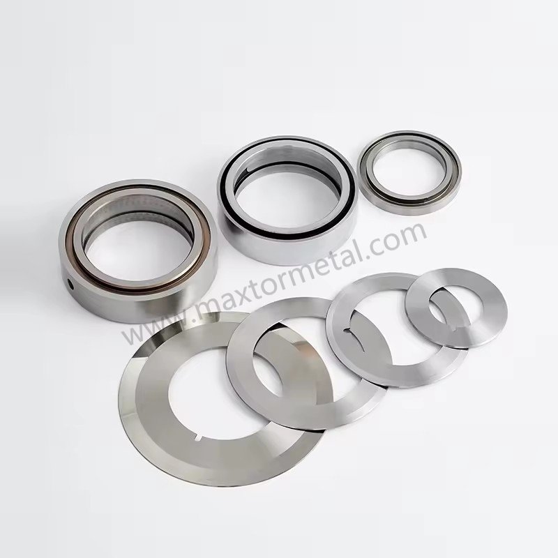
الحدة، الانحراف، التداخل، الميل
غالباً ما تبدأ انحرافات مسار السهم بانحياز جانبي صغير ومتكرر. في العديد من المسارات، أسرع طريقة لإثبات أو دحض الانحراف الناتج عن حركة السكين هي قياس المسافة بين نقاط الانطلاق في المواضع المهمة.
- حدة: الحافة غير الحادة تزيد من قوة القطع ويمكنها "توجيه" الشبكة، خاصة في الأغشية الرقيقة عند السرعات العالية.
- مسافة الدوران (TIR)افحص أكتاف المحور، وأسطح الفواصل، وأسطح الشفرات - وليس نقطة واحدة ملائمة فقط. حافظ على إجمالي الانحراف المحدد ضمن ≤0.025–0.050 مم (0.001–0.002 بوصة) في جميع أنحاء المجموعة. تسجل سجلات فحص المواد الواردة في Maxtor Metal نسبة الانحراف الكلي الداخلي (TIR) عند كل من وجه السكين وسطح تلامس المحور لكل دفعة، بحيث يمكن مقارنة القياسات الميدانية ببيانات المصنع الموثقة عند ظهور مشكلة انحراف بعد تغيير السكين. للاطلاع على معالجة الانحراف الكلي الداخلي المحوري والقطري - بما في ذلك بروتوكولات التحقق من الانحراف من البارد إلى الساخن وآليات العيوب التي ينتجها كل نمط من أنماط الانحراف - انظر أكسيالانحراف الكلي، والانعكاس الكلي الداخلي الديناميكي، وجودة حافة الشق.
- التداخل / المشاركةاضبط قيمة التداخل على الحد الأدنى المستقر لطريقتك ومادتك (عادةً ما تبدأ من 0.5–1.2 مم / 0.020–0.045 بوصة (للقص القياسي للأغشية الرقيقة). قد يؤدي التداخل الزائد إلى إخفاء مشكلة ميكانيكية مؤقتًا مع إضافة الحرارة والحمل الجانبي. بالنسبة للأغشية الرقيقة (PE/PP/PET < 50 ميكرومتر)، يستخدم فريق الهندسة الميدانية في Maxtor Metal نطاق 0.50-0.75 مم كنطاق ابتدائي، ويُعدّله بناءً على جودة الحافة واتجاه قوة القطع. للاطلاع على شرح كامل لكيفية تفاعل التداخل وزاوية الميل والحمل المسبق الزنبركي أثناء الإعداد، انظر إعداد زنبركي لقص القطع بدون خلوص: التحكم في التداخل وزاوية الميل والتحميل المسبق.
- كانت / ترامحافظ على زوايا الميل ضمن مواصفات الشركة المصنعة (عادةً 0.25°–0.5°). إذا لم يتم ضبط الآلة بشكل صحيح، فقد تحصل على قطع يبدو مقبولاً عند الإعداد ولكنه يصبح غير مستقر مع ازدياد القوى مع السرعة.
بالنسبة لمراجع القطع بالقص، يُعد دليل DIENES المرجعي للقطع بالشق أساسًا مفيدًا لكيفية التعامل مع التداخل كمتغير مُتحكم فيه بدلاً من كونه إعدادًا قائمًا على مبدأ "كلما زاد كان أفضل" (انظر دليل ديينز المرجعي للشق، الطبعة الثانية (PDF)).
بالنسبة للخطوط التي تخضع فيها خيارات الطلاء للمراجعة أيضًا - لا سيما ما إذا كانت طلاءات DLC أو PTFE تؤثر على سلوك الانحراف وفترات التنظيف - انظر دليل اختيار طلاءات DLC مقابل PTFE لشفرات الشق الدائرية: التآكل مقابل انتقال المواد.
صلابة الحامل والحمل الجانبي
حتى مع السكاكين الجيدة، فإن الحامل المرن أو المجموعة التي تسمح بتغير الحمل الجانبي ستتحول إلى انحراف عند السرعة.
الشيكات التي عادة ما تؤتي ثمارها:
- تأكد من أن الحوامل مثبتة بشكل مسطح ومثبتة بشكل متسق عبر المجموعة.
- افحص وجود علامات التآكل أو الاحتكاك أو التلف التي تشير إلى حركة دقيقة تحت الحمل.
- تحقق من أن الفواصل لا تتسبب في "تراكم التفاوتات" في انحياز جانبي (خاصة في عمليات البناء متعددة المسارات).
- انتبه لزيادة الأحمال الجانبية التي ترتبط بزيادة حجم اللفائف أو ارتفاع درجة الحرارة.
غالباً ما تعود مشاكل تراكم الفواصل إلى دقة ملاءمة التجويف. للاطلاع على منطق اختيار الملاءمة وفقاً لمعيار ISO 286 الذي يحدد دقة تحديد موقع التجويف بالنسبة للمحور، وكيفية التحقق من استقامة الشفرات الكلية المجمعة قبل دخول مجموعة الشفرات مرحلة الإنتاج، انظر التفاوت في قطر التجويف المركزي والانحراف: تحسين تركيبات ISO 286 لسكاكين القطع عالية السرعة.
تؤثر جودة المواد الموردة على استقرار الإعداد أكثر مما يدركه معظم الفرق. فمجموعات السكاكين ذات الصلابة غير المتناسقة أو التباين في الأبعاد تُدخل متغيرًا يبدو وكأنه مشكلة في الإعداد ولكنه لا يستجيب لتعديلات الإعداد.
يوثق برنامج Maxtor Metal الصلابة، والفحص البُعدي، وسجلات تتبع الحرارة/الدفعة لجميع شحنات سكاكين القطع الدائرية - لذلك عندما تظهر مشكلة انحراف بعد تغيير السكين، يمكن أن يبدأ التحقيق من البيانات التي تم التحقق منها حول الدفعة الواردة بدلاً من العمل بشكل عكسي من الأعراض.
بالنسبة لمشاريع OEM/ODM حيث يجب أن تتطابق السكاكين مع الحوامل القديمة أو المحاور أو الرسومات الهندسية، فإن Maxtor Metal توفر دعمًا كاملاً للمواصفات المخصصة لتجنب تحويل استبدال السكين البسيط إلى دورة تجريبية من الأخطاء الهندسية.
للاطلاع على حسابات التراكم التي تحكم كيفية تراكم اختلاف سمك كل سكين في خطأ عرض الشق عبر إعداد متعدد المسارات، ومنهجية مطابقة الفواصل لتقليل الإزاحة المحورية عند التغيير، انظر التحكم في التفاوت التراكمي في السماكة في عملية القطع متعددة الشفرات.
خيارات القص مقابل الشفرة مقابل السحق
قم بمطابقة طريقة القطع مع المادة والعيب الذي تحاول إصلاحه:
قبل اختيار طريقة القطع، يجب أن تتوافق هندسة الشطف مع صلابة الركيزة؛ فالشطف الأحادي الذي يُناسب أغشية البولي إيثيلين الرقيقة سيختلف أداؤه على رقائق البولي إيثيلين تيريفثالات. للاطلاع على إطار عمل لاختيار القطع بناءً على الصلابة، والذي يشمل الشطف الأحادي والمزدوج والمركب، انظر شطفات مفردة ومزدوجة ومركبة لسكاكين القطع الدائرية.
- القص والقطعيُعدّ هذا الخيار الأمثل عندما تحتاج إلى جودة حواف ثابتة مع إمكانية الحفاظ على هندسة القطع (الانحراف، التداخل، الحمل الجانبي). ويكون مستقرًا عادةً عندما تكون البنية الميكانيكية الأساسية صحيحة.
- شق بشفرة حلاقةبسيط ونظيف على الأغشية الرقيقة، ولكنه حساس لحالة الشفرة، وموضع الأخدود، وثبات الشريط. يُعد موضع الأخدود مهمًا: فإذا كان الأخدود ضحلًا جدًا مقارنةً بسُمك الشريط، تنحرف الشفرة جانبيًا تحت تأثير شد الشريط، ويتغير مسار القطع مع تغير سرعة الشريط؛ أما إذا كان عميقًا جدًا، فيلتف الشريط حول حواف الأخدود، ويصبح التتبع حساسًا لأي تباين في الشد الجانبي. كما يمكن أن يظهر الانحراف بسرعة عندما يتحرك الشريط على طبقة هوائية بسرعة، أو عندما يزيد الشحن الساكن من الالتصاق الجانبي بأسطح التوجيه.
- سحق وشق: يمكن أن يكون متسامحًا في بعض الإعدادات ولكنه قد يزيد أيضًا من الانحراف عندما تختلف ظروف المطاط/السندان أو عندما تتراكم الحرارة.
| فئة الركيزة / الفيلم | الطريقة الموصى بها | الميزة الرئيسية | عامل خطر الانجراف |
|---|---|---|---|
| البولي أوليفين الرقيق (BOPP / PE) | شفرة حلاقة في أخدود / مقص | حافة شق نظيفة، غبار قليل | انحراف الشفرة، والطفو في الهواء |
| صلب / ذو معامل مرونة عالٍ (PET، PVC) | القص والقطع | هندسة قطع دقيقة، حواف نظيفة | انحراف السكين، عدم محاذاة الزاوية |
| أغشية سميكة / مغلفة | القص / السحق الشديد | قدرة عالية على تحمل قوى القص | تفاوت التحميل الجانبي، تآكل الشفرة |
للاطلاع على إطار عمل قائم على تصميم التجارب يوضح كيفية تفاعل عمق التداخل والخلوص الجانبي عبر فئات الركائز هذه - بما في ذلك نموذج مقايضة باريتو بين جودة الحافة وعمر السكين - انظر تحسين عمق تداخل السكين الدائري والخلوص الجانبي.
إذا كنت ترى قطعًا تشبه الثعبان فقط على بعض وحدات التخزين، فأعد تقييم ما إذا كانت الطريقة تتناسب مع سمك الفيلم، ومعامل المرونة، ومعامل الاحتكاك، ونطاق السرعة.
التحكم في الشد واللف
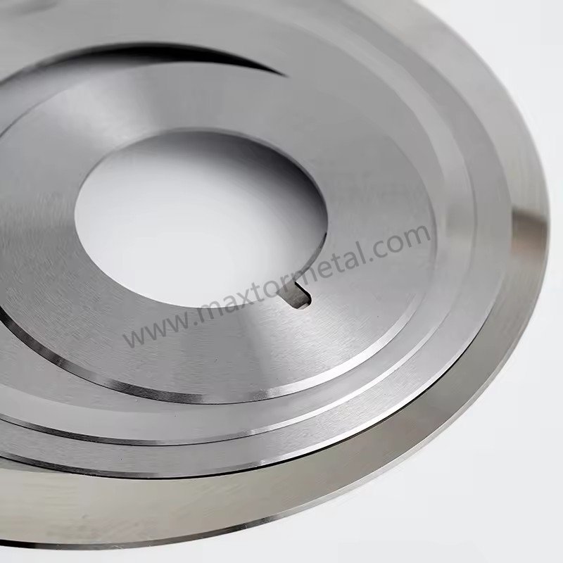
نقاط الضبط والملفات الشخصية
التوتر ليس مجرد رقم، بل هو نمط يتغير عبر المناطق وعلى مدار الزمن. يعتمد مسار الشق المستقر على حالة إجهاد مستقرة للشبكة.
قواعد عملية لا تزال قائمة:
- حافظ على استقرار التوتر عبر فكّ ← معالجة ← إعادة لف, والتحقق من قياسات خلية الحمل الفعلية مقابل نقاط ضبط وحدة التحكم. تغيرات الشد التي تتجاوز ±5%–8% غالباً ما تكون الانحرافات عن الهدف كافية لإحداث انزلاق جانبي في الشبكة وبدء انحراف خط الشق. يستخدم فريق Maxtor Metal الميداني هذا النطاق ±5%–8% كعتبة للإشارة عند مراجعة سجلات الشد أثناء التحقيقات اللاحقة للانحراف على خطوط العملاء.
- استخدم شد التناقص بشكل مقصود؛ فمع زيادة القطر، غالباً ما يكون من الضروري تقليل الشد لتجنب التداخل أو انبعاج الحواف أو سحق النوى.
للحصول على نقطة انطلاق قائمة على المعايير فيما يتعلق بتوجيهات شد الأشرطة، تنشر TAPPI وثائق توجيهية للشد مثل: TAPPI TIP 0200-01:2021 (إرشادات شد الويب).
أعمدة تفاضلية ونقطة تلامس
غالباً ما يكون التفاوت في اللف هو الفرق بين "المسارات التي تتصرف" و "المسارات التي تنحرف". عندما تكتسب المسارات قطراً بمعدلات مختلفة قليلاً، يحتاج النظام إلى طريقة مضبوطة لمعادلة عزم الدوران حتى لا يترهل أحد المسارات ويبدأ في الانحراف.
التحقق:
- تأكد من أن العناصر التفاضلية تنزلق بالفعل تحت نطاق عزم الدوران المتوقع.
- تحقق من توازن حمل الضغط عبر سطح الأسطوانة؛ حيث يمكن أن يؤدي الضغط غير المتساوي إلى اختلافات في السحب بين المسارات.
- راجع الشد التدريجي جنبًا إلى جنب مع الإعدادات التفاضلية؛ فإذا قمت بزيادة الشد مع زيادة القطر، فقد يؤدي ذلك إلى زيادة الحمل على مسار واحد وتزعزع استقرار التتبع.
المراحل الانتقالية وقوة السحب
العديد من القطوع المتعرجة هي “عيوب انتقالية”:
- التسارع إلى سرعة الإنتاج
- مرور الوصلة
- انتقال البرج
- تغير صلابة اللفة مع زيادة القطر
أثناء المراحل الانتقالية:
- تأكد من اتساق سحب مسار الشريط (عدم حدوث انزلاق مفاجئ عند أسطوانة معينة).
- قلل السرعة لفترة وجيزة كإجراء تشخيصي. إذا قل الانحراف فورًا، فابحث في ديناميكيات الهواء/السحب/الكهرباء الساكنة قبل تغيير السكاكين.
- تعامل مع تذبذب موجه الحواف كعرض—غالبًا ما يكون ناتجًا عن تذبذب الشد، أو عدم المحاذاة، أو السحب غير المستقر.
المحاذاة ومطابقة السرعة
الأسطوانات، والأعمدة، وتوازن الضغط
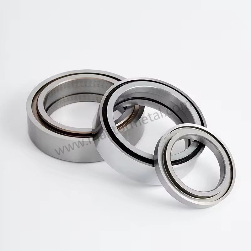
إذا كان الشريط يُجبر على الانحراف جانبًا بسبب الهندسة الهيكلية للمسار، فلن تتمكن أي إعدادات للسكين من “إبقائه مستقيمًا” بشكل مستمر.
- تحقق من توازي الأسطوانات بالنسبة لخط منتصف الآلة.
- افحص أسطح الأسطوانات بحثًا عن التدرج، أو التآكل، أو التلوث، أو التلف.
- تحقق من توزيع ضغط التلامس؛ حيث يمكن أن يؤدي الضغط غير المتساوي إلى توجيه الشريط.
مرجع عملي حول أساسيات تتبع خط المنتصف وأسباب الحركة الجانبية هو تجميعة Walker في مجتمع معالجة الأشرطة (انظر Web Lines: Walker on Web Handling (ملف PDF تجميعي 2003–2014)).
فرق السرعة عند نقطة تلامس القص
بالنسبة للقص الدائري، يمكن أن يؤدي عدم تطابق السرعة إلى توليد قوة جانبية عند موضع القطع.
قائمة التحقق:
- تحقق من مطابقة السرعة السطحية للسكين مع سرعة الشريط حيثما تتطلب طريقة القص ذلك.
- تأكد من أن قارنة المحرك/خلوص التروس لا تسبب تباينًا دوريًا في السرعة.
- إذا كان الانحراف يتناسب مع السرعة وليس الشد، فاشتبه في مطابقة السرعة والاهتزاز.
سلامة المحامل والاهتزاز
تتنكر مشاكل المحامل والاهتزاز دائمًا في صورة “مشاكل قص”.
- قارن درجات حرارة المحامل بين الجانبين الأيسر والأيمن.
- استمع لأي ضوضاء دورية؛ وتحقق من وجود علامات نمطية متكررة.
- إذا كان لديك نظام مراقبة الاهتزاز، فقم بتسجيل أطياف الاهتزاز عند رأس القص ووحدة إعادة اللف.
تأثيرات المادة والهواء
ملف السُمك والتباين
يؤدي تباين السُمك عبر الشريط والتقوس إلى إجهاد غير متساوٍ عبر المسارات. وسيتجه الشريط عمومًا نحو الجانب الأكثر شدًا.
التحقق:
- تحقق من اتساق ملف اللفة الواردة وصلابتها.
- ابحث عن الاختلافات بين المسارات التي ترتبط بموضع اللفة الأم (الحافة مقابل المركز).
- إذا كان الانحراف يحدث فقط في دفعات معينة، فقم بتسجيل معرف الدفعة وبيانات ملف السُمك في سجلك.
انحباس الهواء والضغط السطحي
يعتبر الهواء “عنصرًا ميكانيكيًا” حقيقيًا عند السرعات العالية. فإذا كان الشريط يسير على طبقة رقيقة من الهواء، تتغير قوة السحب ويمكن أن ينحرف القطع.
التحقق:
- راقب الرفرفة وضعف الضغط السطحي عند إعادة اللف.
- استخدم أسطوانة الضغط/التلامس بفعالية (ضمن حدود الآلة) لتقليل الهواء المحتبس.
- كإجراء تشخيصي، قلل السرعة بشكل طفيف وانظر ما إذا كان الانحراف يقل.
الارتباط بين الكهرباء الساكنة وعيوب الحواف
يمكن للشحنات الساكنة أن تجذب الفيلم نحو الموجهات/الأسطوانات، وتجذب الغبار، وتجعل نقاط الفصل غير مستقرة—خاصة في الأفلام الرقيقة عند السرعات العالية.
التحقق:
- تحقق من استمرارية التأريض/الربط عند الأسطوانات الرئيسية.
- افحص قضبان التأيين للتأكد من نظافتها وكفاءة تشغيلها.
- تتبع ما إذا كان العيب يزداد سوءًا في ظروف الرطوبة المنخفضة.
When static-attracted dust is itself a product quality problem—not just a trigger for tracking instability—the blade-level root causes of dust generation (Ra, carbide microstructure, overlap-induced secondary rubbing) require a separate analysis. See تحليل السبب الجذري لتوليد غبار الشق الطولي: خشونة جانب الشفرة Ra، البنية المجهرية للكربيد وتفاوتات الضبط.
FAQs:
س: ما الذي يسبب القطع الثعباني أثناء تقطيع الأغشية؟
ج: ينجم القطع الثعباني عادةً عن عدم الاستقرار الجانبي: القوى المؤثرة على الشفرة (انحراف الشفرة، التداخل، حركة حامل الشفرة)، أو ميكانيكا الشريط (عدم توازن الشد، مشاكل اللف التفاضلي)، أو الهندسة (عدم المحاذاة، ضغط الدف غير المنتظم)، أو الديناميكيات (احتباس الهواء والكهرباء الساكنة). أسرع طريقة للحل هي تحديد ما إذا كان الانحراف يبدأ عند الشفرة أم يظهر أثناء عملية اللف.
س: كيف أعرف ما إذا كان انحراف خط التتقطيع ناتجاً عن مشكلة في الشفرة أم في الشد؟
ج: إذا كانت المشكلة محصورة في مسار واحد محدد وتبدأ مباشرة عند وحدة التقطيع حتى عند السرعات المنخفضة، فمن المرجح أن تكون المشكلة في الشفرات أو الانحراف (Runout) أو حاملات الشفرات. أما إذا تفاقمت المشكلة مع زيادة قطر اللفافة، أو تحسنت عند تغيير الشد، أو تحركت مع تغيير موضع البكرة (Core)، فالمشكلة تعود إلى الشد أو اللف التفاضلي.
س: هل يمكن أن يتسبب انحراف الشفرة (Runout) في انحراف مسارات التقطيع؟
ج: نعم. حتى الانحراف الضئيل يمكن أن يخلق قوة جانبية متكررة تؤدي إلى إزاحة مسار التقطيع. قم بفياس الانحراف عند عمود الدوران (Arbor)، وأسطح الفواصل (Spacers)، وأسطح الشفرة باستخدام مؤشر قياس دقيق (Dial indicator)، وقارن المسارات "الصلحة" بالمسارات "التالفة".
س: ما هي إعدادات الشد التي تساعد في إيقاف انحراف خط التقطيع على آلة التقطيع وإعادة اللف (Slitter Rewinder)؟
ج: ابدأ بتثبيت الشد في كل منطقة والتحقق من الشد الفعلي عن طريق القياس. ثم استخدم ملف تعريف الشد المستدق (Taper profile) الخاضع للتحكم حتى لا يتراكم الشد مع زيادة القطر. يمكن أن تساعدك إرشادات TAPPI المنشورة في اختيار النطاق الأولي، ثم قم بالتعديل بناءً على صلادة اللفافة واستقرار المسارات.
س: هل تمنع أعمدة الدوران التفاضلية (Differential shafts) انحراف المسارات وحدوث التداخل التلسكوبي (Telescoping)؟
ج: تساعد هذه الأعمدة عندما تنمو أقطار المسارات بشكل غير متساوٍ، حيث يعمل الانزلاق الخاضع للتحكم على موازنة عزم دوران الشد حتى لا يرتخي أي مسار أو ينحرف. ومع ذلك، إذا انحشرت عناصر الاحتكاك أو تم ضبط عزم الدوران بشكل خاطئ، فقد تستمر الفروق في صلادة اللفافات بين المسارات وانحرافها.
س: لماذا يتفاقم انحراف خط التقطيع عند السرعات العالية؟
A: Höhere Geschwindigkeiten verstärken den Lufteinschluss, vergrößern Vibrationen und lassen geringfügige Fehlausrichtungen stärker ins Gewicht fallen. Nimmt das Auswandern beim Verlangsamen der Anlage rasch ab, liegt die Ursache wahrscheinlich in der Luftdynamik, der Traktion oder der Statik, bevor Sie die Messergeometrie verändern.
س: كيف يمكنني تقليل احتباس الهواء عند لف الأغشية؟
ج: قم بتحسين فاعلية بكرة الضغط/اللامس (Lay-on/Nip) ضمن حدود الآلة، وتأكد من هندسة مسار الشريط نحو إعادة اللف، واضبط الشد/التطابق المستدق (Taper) بحيث يتكيف الشريط مع اللفافة بدلاً من الركوب على طبقة رقيقة من الهواء. يُعد اختبار تقليل السرعة طريقة سريعة للتحقق مما إذا كان الهواء هو السبب في عدم الاستقرار.
س: أين يجب تسجيل البيانات لمنع تكرار ظاهرة التقطيع المموج (Snake cuts)؟
ج: قم بالتسجيل حسب معرف اللفافة (Roll ID) والمسار: تجميعة طقم الشفرات (القطر الخارجي للشفرة، السمك، الفواصل)، قراءات الانحراف (Runout)، إعدادات التداخل (Overlap) وزاوية الانحراف (Cant angle)، الشد حسب المنطقة وملف التدرج المستدق (Taper)، نوع وإعدادات عمود إعادة اللف، السرعة، حالة التخفيف من الرطوبة/الكهرباء الساكنة، وما إذا كان الانحراف قد تغير مع السرعة أو زيادة قطر اللفافة.
الخاتمة
يتطلب القضاء على القطع الثعباني (Snake cuts) التخلي عن الضبط العشوائي القائم على التجربة والخطأ، واعتماد نهج تشخيصي منهجي قائم على الفيزياء. من خلال التحقق المنهجي من هندسة الشفرة وصلابة الحامل (مع الحفاظ على مؤشر الانحراف الكلي TIR ≤ 0.050 مم والتداخل وزاوية الميل المناسبين)، وتثبيت مخططات شد الشريط عبر مناطق اللف، وإزالة عدم محاذاة بكرات الآلة واحتباس الهواء عند السرعات العالية، يمكن لخطوط تحويل الشريط تحقيق استقرار فوري لخط التقطيع.
لتحويل قائمة التحقق هذه إلى مكاسب التشغيلية دائمة، يجب على المصانع صياغة هذه الفحوصات ضمن إجراءات التشغيل القياسية (SOP). إن تطبيق ورقة إعداد معيّنة — تشتمل على موافقات إجبارية لقراءات الانحراف (Runout)، والتداخل (Overlap)، وقراءات الشد — وإرساء جدول زمني صارم للصيانة الوقائية (PM) لحوامل الشفرات والأعمدة والمحامل، يقلل بشكل كبير من تباين عمليات التغيير والإعداد.
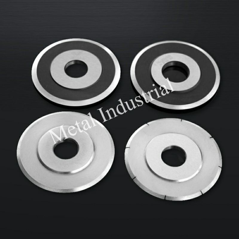
بالنسبة للمصانع التي تعمل على توحيد المعايير الفنية للأدوات عبر خطوط تقطيع متعددة، توفر Maxtor Metal شفرات القص الدائرية مع توثيق كامل للأبعاد والصلادة لكل دفعة، بالإضافة إلى تقديم دعم OEM/ODM عندما تتطلب الشفرات التوافق مع المخططات الهندسية الحالية للأعمدة وحوامل الشفرات. السكاكين الدائرية والشفرات من Maxtor Metal كمرجع للأشكال الهندسية والمواصفات.
في النهاية، يرجع قياس نجاح عناصر التحكم في الاستقرار هذه إلى مؤشرات الأداء الرئيسية. وتتبع عمليات التحويل عالية الأداء خمسة مؤشرات أداء رئيسية أساسية للتحقق من أداء القص لديها:
- معدل الخردة والهدر (%): خفض مباشر في هدر الفيلم المقصوص واللفات المرفوضة غير المطابقة للمواصفات.
- فعالية المعدات الإجمالية (OEE): Higher running speeds and sustained cut stability.
- Unplanned Downtime: Fewer line stops caused by web breaks or mid-run adjustments.
- Blade Service Life: Extended tool durability resulting from minimized side loading and optimal overlap.
- Customer Quality Complaints: Lower incidence of edge weaves, telescoping, or slitting defects in finished roll shipments.
Author / Technical Reviewer
جيري تشو | Technical Support Specialist (After-sales Service)
Maxtor Metal
Jerry brings 10+ years of cross-industry application experience across paper manufacturing, plastic recycling/crushing, metal slitting, and wood processing. Specializing in resolving real-world slitting challenges—such as cutting burrs, excessive dust, and edge instability—he works directly with field engineering teams to optimize tooling performance and operational reliability.
- الشهادات: Certified Maintenance & Reliability Professional (CMRP), Project Management Professional (PMP®)
- Specialties: On-site slitting troubleshooting, custom blade geometry design, and preventive maintenance SOP development

 English
  Spanish
  Italian
  French
  Portuguese
  Russian
  German
  Arabic
  Hindi
Hindi  Vietnamese
  Indonesian
  Japanese
  Korean