

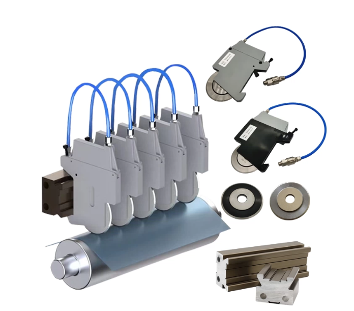
إذا كنت تشق الأفلام رقيقة السُمك أو الأقمشة غير المنسوجة بسرعة عالية، فإن الشق الطولي بالقص يتوقف عن كونه "مجرد إعداد للسكين" ويبدأ في التصرف كمشكلة استقرار: حيث يتحول أي انحراف بسيط، أو تلامس غير متسق، أو تذبذب في ضغط التحميل المسبق الهوائي لحامل السكين إلى عيوب في الحواف وتوقف عن العمل.
تم كتابة هذا الدليل بالنهج العملي الميداني الذي تستخدمه Maxtor Metal عند دعم العملاء في خطوط شق الأفلام والأقمشة غير المنسوجة: تحديد خطوط الأساس من البيانات المقاسة، والتحقق باستخدام الأجهزة، وتوثيق الإعدادات بحيث تكون النتيجة قابلة للتكرار عبر المشغلين وفترات العمل (الورديات)—وليس محبوسة في رأس شخص واحد.
For background on circular knife formats and blade families used in slitting, see Maxtor Metal circular knives and blades (linked here only as a reference point for terminology and typical configurations).
- Who this guide helps: managers, maintenance, process engineers
- What spring-loaded, zero-clearance shear slitting solves: it stabilizes the cut point by maintaining controlled contact as conditions change (speed, tension, thermal growth, minor shaft motion).
- Outcomes: cleaner edges, longer life, higher uptime
أهم النقاط الرئيسية: In high-speed shear slitting, you don’t “set knives.” You control a system: geometry + rigidity + preload + verification. This is the principle Maxtor Metal’s field team applies across all slitting line commissioning and troubleshooting work.
ملاحظات التطبيق والتحقق من الصحة
The setpoints and “baseline windows” in this guide are intended as practical starting points for experienced operators and maintenance teams.
Typical fit (where this guide works best): shear slitting (rotary shear) of thin films and nonwovens on lines using spring-loaded or pneumatic knifeholders, where repeatability at speed depends on controlled overlap/cant/preload and verified runout.
Validate on your line: Knife diameter, holder design (spring vs pneumatic vs hybrid), web structure, speed, tension, temperature growth, and shaft dynamics can shift the stable window. Use short, controlled trials and document results.
If your process differs: crush slitting, score slitting, very low-speed converting, thick/rigid webs, or unusual coatings/adhesives may require different geometry and force strategy—use your OEM guidance as the primary reference.
ملاحظة تتعلق بالسلامة: This article is general guidance and does not replace your OEM manual, site-specific LOTO procedures, or EHS requirements.
المبادئ الهندسية

Spring-loaded setup only works when the fundamentals are right: stable geometry, controlled overlap and cant angle, and mechanical rigidity.
Shear geometry and cut point stability
Shear slitting is a scissor action between overlapping circular knives. In practice, “clean cutting” depends less on how sharp the knives are and more on whether the cut point stays stable as the line accelerates, warms up, and sees tension variation.
This is where a spring-loaded shear slitting setup earns its keep: it helps maintain consistent contact and loading at the cut point with less operator chasing.
What destabilizes the cut point most often:
- Axial runout (wobble) that modulates overlap every revolution.
- الانحراف الشعاعي that changes effective penetration and creates periodic edge signatures.
- Knifeholder compliance (or inconsistent spring/air preload) that lets contact unload at speed.
A fast way to think about it: if the knife pair is not meeting the web the same way at 0°, 90°, 180°, and 270° of rotation, your edge can’t stay consistent.
Overlap and cant angle baselines
Use baselines as starting points, then tune with a controlled trial cut.
Overlap (intersection depth) baselines for rotary shear slitting overlap setting:
- Thin plastic films: ~0.50–0.75 mm (≈0.020–0.030 in)
- Nonwovens: ~0.75–1.0 mm (≈0.030–0.040 in)
For a full DOE-based treatment of how overlap depth and side clearance interact across substrate types—including Pareto trade-offs between edge quality and knife life—see تحسين عمق تداخل السكين الدائري والخلوص الجانبي.
These ranges reflect the practical starting points Maxtor Metal’s engineering team uses when commissioning new slitting lines or troubleshooting unstable edge quality in film and nonwoven converting projects. If overlap is too low, you’ll see incomplete separation, tearing, or intermittent edge defects. If overlap is too high, you’ll see “plowing,” scalloped edges, excess dust, and accelerated wear.
Quick field signals (overlap too low vs too high):
- Too low: intermittent separation, edge starts to “zipper” at speed, defects worsen with tension variation.
- Too high: rising dust, visible scallop/wave signature, faster heat build-up and polish bands on the knife contact zone.
Cant angle baselines for cant angle shear slitting film setups:
- Plastic film: ~0.25–0.5°
- Nonwovens: ~0.75–1.0°
Maxtor Metal’s field experience across BOPP, PE, and PET slitting projects consistently shows that exceeding 0.5° cant angle on thin films accelerates bevel wear at the nip contact zone—validating the conservative upper bound of this window. If cant angle is too low, the knives tend to rub (heat/dust) and traction at the nip becomes unreliable. If cant angle is too high, the nip becomes overly aggressive and blade wear (and sometimes edge nicking/chipping) increases.
Quick field signals (cant angle too low vs too high):
- Too low: rubbing/heat, adhesive pickup, dust without clean separation.
- Too high: faster wear, edge damage risk increases, and the cut can become “grabby” at the nip.
A useful cross-check is to confirm your setup logic against an established industry slitting reference guide. These references typically summarize the practical relationships among overlap, shear angle, and measurable outcomes—useful for aligning your team on a common starting baseline.
Mounting rigidity and runout targets
If you want a stable zero-clearance shear slitting setup, you need targets that your maintenance team can actually measure.
Practical runout targets (typical baselines):
- Axial TIR (knife face/edge): aim around 0.002 in
- Radial TIR (knife OD): aim around 0.004 in
These numbers come from runout target baselines commonly cited in industry slitting setup references and are useful as a starting point for maintenance. For the bore-fit logic that underpins these targets—including ISO 286 H7/h6 vs H7/g6 selection and assembled TIR verification routines—see التفاوت في قطر التجويف المركزي والانحراف: تحسين تركيبات ISO 286 لسكاكين القطع عالية السرعة.
How to measure (quick method):
- Lock bottom knives to the driven shaft.
- Place a dial indicator on the knife edge (axial) and rotate slowly; repeat on the OD (radial).
For shear slitting, holder bearing condition also matters. A common diagnostic is to confirm the knifeholder bearing does not show excessive radial/axial runout; many industry shear-slitting maintenance guides emphasize the same troubleshooting logic: mechanical condition first, then process adjustments.
المعايرة والإعداد المحمل بنوابض

The goal of spring-loaded knifeholders is to make “contact” a controlled variable, not something that drifts with temperature, minor shaft movement, or operator feel.
Zero-clearance contact and verification
مدخل: clean arbors/bores/spacers, sharp knives, guarded access, and a runout measurement baseline.
فعل:
- Clean and inspect mating surfaces (arbor shaft, spacer faces, knife bores). One trapped chip can become runout.
- Assemble with rigidity in mind: minimize spacer count per pocket; keep the largest spacer nearest the knife where possible.
- Bring knives to zero-clearance contact at the intended cut point using your holder’s adjustment method.
Verify (done when…):
- You can confirm consistent contact around rotation (no “high spot only” contact).
- Your axial/radial runout is within your plant target window before you tune parameters.
If you need a repeatable method for documenting these checks, keep a simple setup sheet that records: knife OD, overlap, cant angle, preload/air pressure, speed, tension, and a quick edge-quality score.
Setting overlap and micro-preload pressure
Zero clearance does not mean “maximum force.” For thin webs, the best setup is usually minimum effective force that keeps the nip stable.
Overlap:
- ابدأ بـ 0.030–0.040 in overlap for nonwovens and similar compliant webs.
- Start slightly lower for many films, then increase only if separation is unstable.
Micro-preload (airflow/pressure):
- Use the holder’s air assist as a micro-preload, not a clamp.
- A common working window is 20–60 psi at the holder supply (actual force at the knife depends on cylinder area, regulator accuracy, and friction losses).
Quick field signals (preload too low vs too high):
- Too low: contact unloading at speed, lane-to-lane inconsistency, defects increase as speed ramps.
- Too high: unnecessary friction/heat, faster polishing wear bands, and potential web damage (especially on softer structures).
Verify (done when…):
- يمكنك التشغيل بالسرعة المستهدفة دون فقدان التلامس (لا تزداد تكرارية عيوب الحافة مع زيادة السرعة).
- نمط تآكل السكين متساوٍ (لا توجد أشرطة لامعة موضعية تشير إلى تلامس متقطع).
الضبط المباشر والتوثيق
الضبط المباشر هو العملية التي تحول بها خطوط الأساس إلى إجراءات تشغيل قياسية (SOP) قابلة للتكرار. يستخدم فريق الهندسة الميدانية في Maxtor Metal تسلسلاً متسقًا للإجراءات لتجنب التعامل مع متغيرات متعددة في وقت واحد.
تسلسل الإجراءات (حافظ على اتساقه):
- قم بإجراء تجربة قصيرة بسرعات الإنتاج مع تثبيت إعدادات خط الأساس لديك.
- يُعدِّل متغير واحد في كل مرة—التداخل أولاً، ثم زاوية التميل (cant angle)، ثم التحميل المسبق. لا تقم أبدًا بتغيير متغيرين في وقت واحد.
- بعد كل تعديل، أعد فحص الحافة وسجّل التغيير قبل المتابعة.
ما يجب تسجيله (كحد أدنى):
- نقطة ضبط التداخل، وزاوية التميل، ونقطة ضبط ضغط الهواء، وسرعة الخط، وشَدّ الشريط (web tension)، وجرعة المادة (material batch).
- رمز عيب سريع لكل تجربة: التوبر (fuzzing) / التسنن الدقيق (feathering) / التمزق (tearing) / التموج (scallop) / التغبير (dusting).
Verify (done when…):
- يمكن لعمّال تشغيل اثنين إعادة إنتاج نفس جودة الحافة في ورديات مختلفة باستخدام نفس الإعدادات المسجلة دون الحاجة إلى تسليم شفهي.
احتفظ بنموذج الإعداد (انظر أدناه) ممتلئًا لكل تشغيل تجريبي. بمجرد أن تؤكد ورديتان متتاليتان استقرار جودة الحافة، تصبح الإعدادات الحالية هي خط الأساس المعتمد لتلك المادة.
قوائم مراجعة إجراءات التشغيل القياسية (SOP) (قابل للطباعة)
قائمة التحقق قبل البدء (قبل إجراء التلامس بين السكاكين)
- التحقق من حالة إجراءات إغلاق المصادر وحظر التشغيل (LOTO)/ الحماية والدخول المحكوم.
- تنظيف عمود الدوران (arbor)/ الثقوب/ أوجه الفواصل؛ وإزالة المواد اللاصقة والرقاقات العالقة.
- التأكيد على مخطط تجميع الفواصل (تقليل الفواصل النحيفة؛ وضع الفاصل الأكبر بالقرب من السكين قدر الإمكان). للحصول على الحسابات الرياضية للتجميع وانضباط مطابقة الفواصل الذي يمنع انزياح المحور من التراكم عبر المجموعة، راجع التحكم فيالتفاوت التراكمي للسمك في عملية التقطيع متعدد السكاكين.
- التحقق من حالة قفل/محرك السكين السفلي وسلامة محامل الحامل.
- قياس وتسجيل خط الأساس للحيود الداخلي/الخارجي (الحيود المحوري/القطري TIR).
قائمة التحقق من القطع التجريبي (أول 5–10 دقائق بسرعات الإنتاج)
- ابدأ من خط الأساس للتداخل/التميل/التحميل المسبق؛ قم بتغيير متغير واحد في كل مرة.
- افحص الحافة للتأكد من خلوها من التسنن الدقيق، والتمزق، والتموج، وتناثر الغبار.
- راقب العيوب المرتبطة بالسرعة (على سبيل المثال، العيوب التي تظهر فقط فوق حد سرعة معين).
- التأكد من استقرار إمداد الهواء تحت الحمل الديناميكي (بدون انخفاض في الضغط).
قائمة التحقق من القبول (التشغيل “جيد بما يكفي لتثبيته”)
- الحافة مستقرة من بدء التشغيل حتى الوصول إلى حالة الاستقرار الحراري.
- عدم وجود نمط عيوب دوري مرتبط بمدار محيط السكين/دوران العمود.
- نمط التآكل متساوٍ عبر شريط التلامس (لا توجد نطاقات صقل موضعية).
- تسجيل الإعدادات (التداخل، التميل، التحميل المسبق، السرعة، الشد، وجرعة المادة).
قائمة التحقق عند تغيير الورديات / تغيير اللفات (التحكم في إمكانية التكرار)
- إعادة فحص نقطة ضبط الهواء وسلوك مقياس الضغط.
- فحص بصري سريع للتأكد من عدم تراكم المواد اللاصقة أو الغبار.
- فحص عشوائي لمحطة واحدة للتأكد من اتساق التلامس (تجنب التلامس في “النقاط العالية فقط”).
- تسجيل أي انحراف والإجراء التصحيحي المتخذ.
قالب نموذج الإعداد (نسخ/لصق)
استخدم سجلاً بسيطًا من صفحة واحدة لجعل النتائج قابلة للتكرار بين جميع المشغلين.
- التاريخ / الورديّة / المشغّل:
- الخط / المحطة / معرف المسار:
- المادة والجرعة: (فيلم/أقمشة غير منسوجة، الهيكل، السمك)
- القطر الخارجي للسكين OD / السمك / تفاصيل الشطب:
- نوع الحامل: (نابضي / نيوماتيكي / هجين) والموديل:
- نقطة ضبط التداخل: ____ (in / mm)
- نقطة ضبط زاوية التميل: ____ (درجة)
- نقطة ضبط إمداد التحميل المسبق (الهواء): ____ (psi / bar)
- سرعة الخط: ____ (m/min)
- شد الشريط (Web tension): ____ (نيوتن N أو وحدتك)
- خط الأساس للحيود (Runout baseline):
- الانحراف المحوري الإجمالي (Axial TIR): ____
- الانحراف الشعاعي الإجمالي (Radial TIR): ____
- تقييم جودة الحافة (1–5) + رموز العيوب: التنسيل / الترييش / التمزق / التموج / التغبير
- ملاحظات (ما الذي تغير، متغيّر واحد في كل مرة):
الأداء والمقاييس
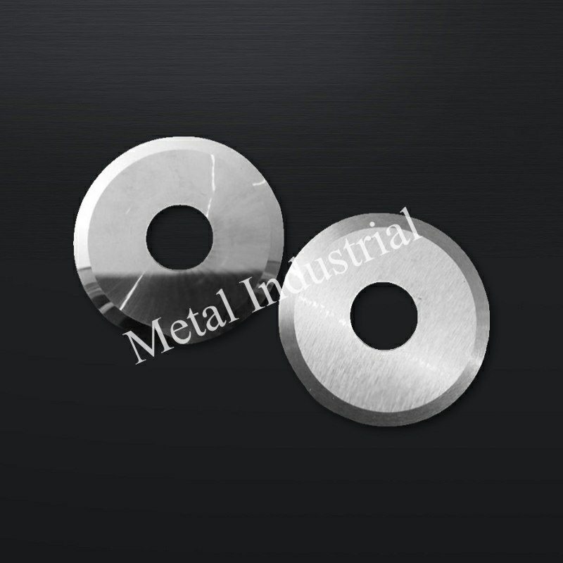
عند السرعات العالية، لا تعتمد جودة الحافة على ضبط “مثالي” واحد بقدر ما تعتمد على بقاء النظام ضمن نطاق تشغيل مستقر.
تتبّع النتائج المرتبطة مباشرة بالتكلفة:
- معدل قبول الحافة (مقبول/مرفوض لكل لفة).
- تكرار العيوب (عدد العيوب لكل 1,000 متر أو لكل لفة).
- وقت التغيير (الدقائق المستغرقة للوصول إلى أول لفة مقبولة).
- حياة السكين (زمن التشغيل أو الأمتار الطولية لكل عملية إعادة تجليخ/تغيير).
إذا ظهرت عيوب الحافة بمسافات دورية تطابق محيط السكين أو دوران المحور، فتعامل معها كدليل على وجود انحراف/نقص في الصلابة—وليس “مشكلة في خامة المادة”.”
نقاط الضبط الموصى بها حسب المادة الركيزة
استخدم هذه النقاط كبدايات عملية، ثم تحقق منها بناءً على خامتك وديناميكيات خط الإنتاج لديك.
نقاط الضبط الابتدائية الموصى بها من Maxtor Metal حسب نوع المادة الركيزة للشق بالقص بدون خلوص والمدعوم بنوابض:
| المادة الركيزة | زاوية الميل (Cant Angle) | تداخل | التحميل الهوائي المسبق (الإمداد) |
|---|---|---|---|
| رقائق البلاستيك الرقيقة (PE/PP/PET، <50 μm) | ~0.25–0.5° | ~0.020–0.030 بوصة (0.50–0.75 مم) | ابدأ بقيمة منخفضة: 20–35 psi؛ وزدها فقط إذا انفصل التلامس |
| الأنسجة غير المنسوجة / الشباك الألياف المرنة | ~0.75–1.0° | ~0.030–0.040 بوصة (0.75–1.0 مم) | نطاق متوسط: 35–55 psi للحفاظ على نقطة تلامس (nip) مستقرة |
| الرقائق المركبة / الشباك المغطاة | أقرب إلى خط الأساس للرقائق (~0.25–0.5°) | اضبط لتقليل التغبير؛ وتجنب كشط الطبقة المغطاة | ابدأ بقيمة منخفضة؛ حيث تسرّع بقايا الطلاء من التآكل إذا كان التحميل المسبق مفرطاً |
نصيحة احترافية: إذا اضطررت لزيادة التحميل المسبق “لإيقاف العيوب”، فتوقف وأعد فحص الانحراف وصلابة مجموعة الفواصل أولاً. يجب أن يعوض التحميل المسبق التغيرات الديناميكية الصغيرة، لا أن يغطي على الأعطال الميكانيكية.
اختيار خامات الشفرات والطلاءات
عمر الشفرة يتعلق بنوع التآكل: التآكل بالاحتكاك، والالتصاق، والحرارة، والتآكل الكيميائي، والتشقق الدقيق لا تتأثر جميعها بنفس نوع الصلب أو الطلاء.
منطق الاختيار الشائع (الممارسة الصناعية العامة):
- صلب الأدوات (مثل D2): يُختار غالباً عند الحاجة إلى مقاومة التآكل وحواف مستقرة في الشباك الكاشطة أو المحشوة.
- الصلب سريع القطع (مثل M2): يُختار غالباً عند الحاجة إلى المتانة وثبات الحافة تحت أحمال حرارية أعلى.
- كربيد: يُستخدم عندما يكون التآكل الاحتكاكي هو السائد مع القدرة على التحكم في مخاطر الهشاشة (المحاذاة والاهتزاز).
للحصول على إطار عمل قائم على الصلابة لاختيار هندسة الشطب الأحادي أو المزدوج أو المركّب قبل البدء في الضبط المدعوم بنوابض، راجع شطفات مفردة ومزدوجة ومركبة لسكاكين القطع الدائرية.
تُختار الطلاءات عادةً لتعديل سلوك الاحتكاك والحرارة والالتصاق:
- TiN / TiCN / CrN عائلات: تُستخدم لتحسين مقاومة التآكل وتقليل التحزيز في العديد من تطبيقات تشكيل المعادن والتحويل.
- محتوى قابل للتنزيل: ذات أهمية خاصة في عمليات الشق بالقص عالية السرعة والمدعومة بنوابض للرقائق الرقيقة، حيث يعني تقليل احتكاك السطح عند نقطة التلامس بقاء الحد الأدنى للتحميل المسبق الفعال منخفضاً—مما يقلل الحرارة وتآكل الصقل، ويوفر نطاق تشغيل مستقر وأوسع عند السرعات العالية. تطبق Maxtor Metal طلاء DLC على السكاكين الدائرية للقص للعملاء الذين يشغلون رقائق PE/PP بسرعة تتجاوز 400 m/min حيث يكون الالتصاق وتدور الحواف الناتج عن الاحتكاك هما نمطا التآكل الأساسيان.
يعتمد العمر الافتراضي الطويل للسكين في نظام التثبيت بالنوابض على الاتساق عبر الشحنات، وليس فقط على الحدة الابتدائية. تحافظ Maxtor Metal على إمكانية تتبع رقم التشغيلة/الصبة لجميع شفرات الشق بالقص، مع توفر سجلات توثيق الصلادة والفحص الأبعادي لكل دفعة. وهذا يعني أنه بمجرد ضبط الإعدادات وتحقيق أداء ممتاز، ستعمل طلبية الشفرات التالية بنفس الطريقة—دون الحاجة إلى جولة جديدة من ضبط المعلمات.
دراسة حالة ميدانية: حامل السكين المحمل بنوابض يعيد الشق الطولي بالقص المستقر ذي الخلوص الصفري
تم التعامل مع الحالة التالية بواسطة الفريق الفني لخدمة ما بعد البيع في Maxtor Metal، برئاسة Jerry Chu، بالتعاون مع مصنع لرقائق التغليف المرنة. ويتم مشاركتها كمثال واقعي لحل المشكلات. تم تجهيل تفاصيل العميل والموقع؛ قد يختلف نطاق الاستقرار الدقيق لديك—تحقق من ذلك على خط الإنتاج لديك.
تطبيق
- مادة: رقائق التغليف BOPP, 30–40 ميكرومتر
- طريقة الشق: الشق بالقص النيوماتيكي المدعوم بنوابض (تلامس بدون خلوص)
- سرعة الخط: 450–650 م/دقيقة (ظهرت العيوب بشكل أساسي فوق ~550 م/دقيقة)
- وضع التشغيل: إنتاج مستمر بنظام ورديات مدتها 12 ساعة؛ حوامل سكاكين قص علوية متعددة على سكة خطية
- إمداد الهواء: حوالي 5–6.0 bar (لوحظ استقراره عند ~5.8 ±0.05 بار)
الأعراض الأولية
بعد حوالي أسبوع واحد من الإنتاج المستمر:
- حواف تقطيع مشرشرة متقطعة
- انبعاثات دورية للغبار الناعم
- خروج مسار تقطيع واحد عن السكين السفلي كل 15–20 دقيقة
- تغير جودة الحواف دون تعديل معايير الإعداد
تسلسل الفحص (الميكانيكي أول
- قياس انحراف السكين (مؤشر القياس الدقيق):
- الانحراف الدائري الكلي (TIR) للسكين السفلى: 008 مم
- الانحراف الدائري الكلي (TIR) للسكين العليا: 010 مم
- كلاهما ضمن الحدود المقبولة للفريق
- فحص مصفوفة الفواصل: أسطح نظيفة، خالية من الرايش، واتساق العرض ممتاز
- فحص المحامل: دوران سلس؛ لا يوجد خلوص غير طبيعي أو ارتفاع في درجة الحرارة
- التحقق من التغذية الهوائية: ضغط مستقر؛ لم يتم العثور على أي تسريبات
السبب الجذري
تحول التركيز إلى آلية حامل السكين المحمّل بزمبرك:
- كان أحد الحوامل يتمتع بقوة سحب يدوي أقل بشكل ملحوظ من الحوامل المجاورة.
- أظهر التفكيك وجود زنبرك إرجاع مجهد جزئياً, contamination في آلية التوجيه، و شوط تعشيق غير منتظم.
عند السرعات العالية، كان الحامل يفقد أحياناً الحمل الجانبي الثابت ضد السكين السفلى. وتنفصل السكين العليا لحظياً ثم تعود للتعشيق، مما ينتج عنه تشرشف دوري، وتدفقات غبار، وانحراف خط التقطيع.
الإجراءات التصحيحية
- استبدال زنبرك الإرجاع المجهد
- تنظيف وتزييت آلية التوجيه
- إعادة ضبط التداخل وإعادة فحص شوط التعشيق
- خفض ضغط هواء الحامل قليلاً بعد التأكد من استقرار تلامس السكين (لتجنب الاحتكاك غير الضروري)
- التحقق من اتساق الحمل الجانبي عبر جميع حوامل السكاكين قبل إعادة التشغيل
النتائج (ورديتا إنتاج)
- حدوث حواف مشرشفة: متقطع كل 15–20 دقيقة ← لم يُلاحظ
- غبار التقطيع: تدفقات مرئية متكررة ← يكاد لا يُلاحظ
- حوادث انحراف السكين: عدة مرات في الوردية ← لم يتم تسجيل أي منها
- الفاصل الزمني لخدمة السكين العليا: الخط المرجعي ← أطول بنسبة ~15–20% قبل إعادة التجليخ (بشكل رئيسي نتيجة تقليل الاحتكاك غير الضروري)
Why lower pressure can extend knife life: once stable contact is maintained, excess pneumatic preload mainly increases sliding friction and heat—accelerating polish wear and edge rounding without improving separation.
Practical lessons learned
- Stable zero-clearance shear slitting depends on consistent side-load, not maximum air pressure.
- If runout, spacers, bearings, and air supply look normal, inspect the holder mechanism (spring condition, guide contamination, engagement stroke).
- A structured order—runout → spacer stack → bearings → pneumatic supply → holder mechanism—reduces wasted blade changes and downtime. For a measurement-first approach to axial and radial TIR diagnosis—including cold-to-hot drift checks—see الانحراف المحوري، والانعكاس الكلي الداخلي الديناميكي، وجودة حافة الشق.
- On adhesive-coated webs where spring-loaded preload is used to maintain zero-clearance contact, adhesive transfer to the blade face is an additional failure mode — one governed by heat-contact feedback rather than geometric drift. For the diagnostic sequence and coating selection logic specific to PSA and adhesive-sensitive constructions, see تراكم المواد اللاصقة على شفرات الشق الدائرية: التغذية الراجعة للتلامس الحراري، واختيار الطلاء، وبروتوكول التشخيص متعدد الطبقات.
- Key calibration steps to standardize SOPs: verify runout/rigidity first, then set zero-clearance contact, set overlap, set micro-preload, and only then tune cant angle and tension with one-variable changes.
- Parameter windows for thin films/nonwovens: films often stabilize around ~0.020–0.030 in overlap and ~0.25–0.5° cant angle, while nonwovens often need ~0.030–0.040 in overlap and ~0.75–1.0° cant angle—then fine-tune for your exact web and speed.
- Next actions: verify runout, log settings, review TCO
If you want to standardize the knife and blade side of that SOP across lines, keep the internal reference for your team here: circular knives and blades for slitting applications.
استكشاف أخطاء الإعداد وإصلاحها
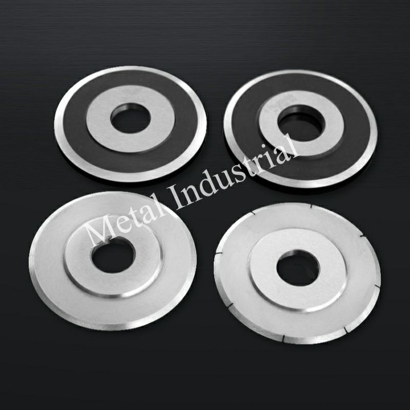
Edge defects and corrective levers
One-page decision tree (symptom → checks → levers)
Use this to keep troubleshooting consistent and avoid “turn everything up.”
1) Is the defect periodic (spacing matches knife circumference or shaft rotation)?
- Yes → Treat as mechanical first:
- Check axial/radial runout → spacer stack cleanliness/rigidity → arbor fit → bearing play
- No → Go to process window checks.
2) Does the defect appear only above a speed threshold?
- Yes → Suspect contact unloading / holder compliance / vibration sensitivity:
- Verify preload stability under dynamic load
- Inspect holder mechanism consistency lane-to-lane
- Re-check engagement stroke and side-load behavior
3) Pick the dominant symptom and adjust one variable at a time (after mechanical checks):
- Feathering/fuzzing → overlap slightly up, cant modestly up (within window), verify tension stability
- Tearing/intermittent separation → overlap up, verify contact unloading, re-check axial runout
- Scallop/plowing signature → overlap down, preload down, verify knives aren’t forcing the web
- Excess dust/heat → verify cant not too low, overlap not excessive, check sharpness and pickup
Use defect-driven adjustment instead of “turn everything up.”
- Feathering / fuzzing (common in nonwovens):
- Increase overlap slightly within your window.
- Increase cant angle modestly if the nip isn’t establishing a clean separation line.
- Verify tension stability at the slitting point.
- Tearing / intermittent separation:
- Check overlap is not too low.
- Check for contact unloading (preload too low, air instability).
- Re-check axial runout; overlap may be oscillating.
- Scalloped / wavy edge (“plowing” signature):
- Reduce overlap.
- Reduce preload (if excessive) and confirm knives aren’t forcing the web into the bottom band.
- Excess dusting:
- Check cant angle is not negative/too low (rubbing).
- Check overlap is not excessive.
- Confirm knife sharpness and surface condition.
Mechanical faults and fixes
When troubleshooting slitting edge defects, separate parameter issues from mechanical ones.
If you need a tighter shorthand for the work order queue, label this block as “slitting edge defects troubleshooting: mechanical checks first.”
Mechanical checks that pay back quickly:
- Verify axial and radial runout against your plant targets.
- Inspect spacer stack: too many thin spacers increases cumulative tolerance error.
- Check knife bores and arbor fit: loose fit or damage will show up as periodic defects.
- Check bearings: play or roughness becomes vibration at speed.
If you need an external reference for measurement practice, follow the same core logic used in many slitting maintenance manuals: lock the driven shaft, measure axial TIR at the knife face/edge and radial TIR at the OD, and record results at a consistent location so trends are comparable over time.
Air system and continuity checks
Stop-and-recheck triggers (don’t “tune through” these)
If you see any of the following, stop changing multiple process knobs and go back to mechanical verification first:
- You have to keep increasing preload just to hold edge quality.
- Defects are periodic with spacing tied to knife circumference or shaft rotation.
- One lane behaves differently from adjacent lanes with the same recipe.
- Edge quality is stable at low speed but collapses above a threshold speed.
These are strong signals of runout, spacer stack issues, bearing condition, or holder mechanism inconsistency (spring fatigue, contamination, engagement stroke).
If your spring-loaded system uses pneumatics, treat air quality and stability as part of process control.
Continuity checklist:
- Regulator holds setpoint under flow (no pressure droop during dynamic load).
- Filter/dryer condition is acceptable (water/oil carryover increases variability).
- No audible leaks; fittings and hoses are secure.
- Gauge accuracy is verified on a schedule.
Done when… you can run from start-up to thermal steady state without needing to “chase” preload.
If setup variables are confirmed correct but lane drift persists, the failure mode has likely shifted to tension, alignment, or air dynamics. For a multi-subsystem diagnostic that sequences these checks, see Stopping Snake Cuts in Film Slitting: A Systems Checklist.
الصيانة والامتثال

Daily to quarterly SOPs
A simple cadence prevents “mystery failures.”
يوميًا:
- Clean knives/holders and check for adhesive pickup.
- Record: overlap, cant angle, preload setpoint, speed, and edge outcome.
أسبوعي:
- Inspect spacer faces and knife bores for nicks and fretting.
- Verify regulator and gauge function.
شهريا:
- Dial-indicator check of arbor runout at a consistent measurement location.
- Confirm bearing condition (noise, heat, play).
Quarterly:
- Review logs: correlate edge defects and knife life to settings.
- Re-validate baseline settings for your top 3 substrates.
Safety and LOTO essentials
Slitting lines store energy (rotational inertia, pneumatic pressure, nip points). Your SOP should align to OSHA requirements for hazardous energy control and guarding.
Two authoritative starting points:
⚠️ تحذير: Zero-clearance setup requires controlled access near rotating elements. Treat stored energy and unexpected restart as first-order hazards, not paperwork.
Traceability and material compliance
If you’re trying to stabilize knife life across quarters (not just across shifts), traceability matters.
Practical expectations to build into procurement and QC:
- Lot/heat identification that ties finished knives back to the source material.
- Documented inspection practices (dimensions, hardness, runout checks) that are consistent between batches.
- Material and substance compliance evidence when required by your end market.
For compliance context:
- REACH overview and legal basis: ECHA’s “Understanding REACH” و EUR-Lex Regulation (EC) No 1907/2006 (REACH)
- RoHS overview and legal basis: European Commission RoHS Directive overview و EUR-Lex Directive 2011/65/EU (RoHS)
(For many converting operations, these frameworks show up as customer flow-down requirements and supplier declarations, even when the slitting line itself is not an electrical product.)
الخاتمة
Spring-loaded setup for zero-clearance shear slitting is a systems problem, not a single-parameter adjustment. The consistent finding from Maxtor Metal’s field engineering work across film and nonwoven converting lines is that edge quality problems almost always trace back to one of four root categories: runout exceeding plant targets, spacer stack compliance, holder mechanism condition (spring fatigue, guide contamination, engagement stroke), or air supply instability under dynamic load.
The practical sequence that works: verify mechanical condition first, establish zero-clearance contact, set overlap and micro-preload to the minimum effective level, then tune cant angle one variable at a time. Log every change. Lock the baseline when two operators can reproduce the same result on different shifts.
Knife and blade material selection sits downstream of this setup discipline—DLC-coated or high-speed steel blades cannot compensate for unstable contact or misaligned runout. When the mechanical system is right, blade life and edge consistency follow. For Maxtor Metal’s blade and coating options for shear slitting applications, see circular knives and blades for slitting applications.
FAQs:
س: ما هو إعداد الشق الطولي بالقص المحمل بنوابض، ومتى تحتاجه؟
ج: يستخدم الإعداد المحمل بنوابض قوة محكومة (نابض أو نيوماتيكي/هوائي) للحفاظ على تلامس مستقر لزوج السكاكين أثناء تشغيل الخط. تحتاجه عادةً عندما تتغير جودة الحافة مع السرعة، أو الإحماء، أو تغير شد اللف من لفة إلى أخرى.
س: كيف أقوم بضبط التداخل (Overlap) على آلة الشق الطولي بالقص الدوار للأفلام الرقيقة؟
ج: ابدأ بحوالي 0.020-0.030 بوصة وزد القيمة فقط حتى يصبح الفصل مستقرًا. إذا تعمقت أكثر من اللازم، فسترى غالبًا حوافًا مموجة (مشرشرة)، وغبارًا إضافيًا، وتآكلًا أسرع للسكين.
س: ما هي زاوية الميل (Cant angle) التي يجب أن أستخدمها لشق الأفلام البلاستيكية بالقص؟
ج: نطاق البدء الشائع هو حوالي 0.25-0.5 درجة. الزاوية المنخفضة جدًا تؤدي إلى الاحتكاك وتوليد الحرارة/الغبار، بينما تؤدي الزاوية العالية جدًا إلى تآكل أسرع. قم بالتحقق من ذلك من خلال تجربة قصيرة بسرعة الإنتاج الكاملة.
س: لماذا أحصل على حواف وبرية (Fuzzy edges) عند شق الأقمشة غير المنسوجة؟
ج: توبير الحواف (Fuzzing) غالبًا ما يكون علامة على أن نقطة التلامس (Nip) لا توفر خط فصل نظيفًا. يمكن أن يساعد زيادة التداخل قليلاً (غالبًا ~0.030-0.040 بوصة) ونطاق زاوية ميل أعلى (~0.75-1.0 درجة)—إذا كان الانحراف (Runout) والشد تحت السيطرة بالفعل.
س: ما هو الانحراف (Runout) المقبول للشق الطولي بالقص عالي السرعة؟
ج: كخط أساس عملي، تستهدف العديد من الإعدادات حوالي 0.002 بوصة من المؤشر الإجمالي لقصور المحور (Axial TIR) و0.004 بوصة من المؤشر الإجمالي لقصور القطر (Radial TIR) عند السكين. إذا تكررت العيوب بتباعد دوري يتطابق مع الدوران، فأعد فحص الانحراف قبل تغيير معلمات العملية.
س: ما مقدار ضغط الهواء الذي يجب أن أستخدمه على حامل السكين النيوماتيكي (الهوائي) المحمل بنوابض؟
ج: استخدم الحد الأدنى من الضغط الذي يمنع انفصال التلامس (Contact unloading) عند السرعات العالية. نافذة التوريد الشائعة هي 20-60 psi، ولكن القوة الفعالة تعتمد على تصميم الحامل واستقرار المنظم، لذا قم بالتحقق من ذلك من خلال جودة الحافة ونمط التآكل.
س: ما هي أسرع طريقة لاستكشاف أخطاء عيوب الحواف وإصلاحها في الشق الطولي بالقص؟
ج: تعامل مع الأمر كشجرة قرار: تأكد من الانحراف/الصلابة أولاً، ثم تحقق من التداخل، ثم زاوية الميل، ثم التحميل المسبق، ثم الشد والتعامل مع الزوائد (الهوالك). تغيير متغيرات متعددة في وقت واحد عادة ما يخفي السبب الحقيقي.
المؤلف / المراجعة الفنية
جيري تشو — Technical Support Specialist, After-sales Service, Maxtor Metal
- 10 years of hands-on technical support experience across industries including papermaking, plastics recycling/crushing, metal coil slitting, and woodworking
- Focus areas: resolving real production issues such as slit-edge burrs and excessive dust generation
- Field methods: dial-indicator runout measurement, holder mechanism checks, and SOP-style setup logging for repeatability
- Certifications: PMP, CMRP

 English
 Spanish
 Italian
 French
 Portuguese
 Russian
 German
 Arabic
 Hindi
 Vietnamese
 Indonesian
 Japanese
 Korean