

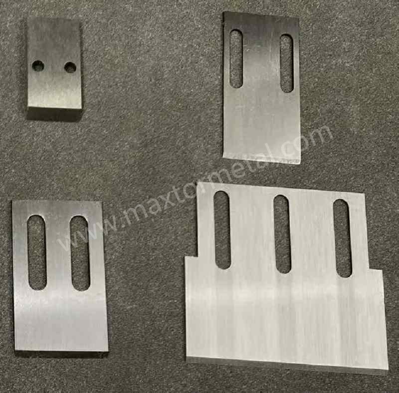
مقدمة
تحوّل الألياف الزجاجية عملية تشغيل البولي أوليفين العادية إلى ملاط كاشط. وتتصرف كل شعيرة مقطوعة كمبرد مجهري، مما يسرع من تآكل واستدارة حواف الشفرات ويحفر أخاديد دقيقة في وجه قالب البثق. النتيجة؟ زيادة في الجزيئات الدقيقة والذيول، واهتزاز متزايد، وتغيير الشفرات أو إعادة شحذها بشكل متكرر. في عمليات تحبيب PP/PE تحت الماء أو بحلقة مائية بنسبة ألياف زجاجية تتراوح بين 10–40%، يظهر هذا التآكل بشكل أسرع ويكلف أكثر من حيث وقت التوقف الضائع وإعادة تهيئة القالب مقارنة بعمليات التشغيل غير المملوءة بالألياف.
الكشط ليس سوى نصف القصة؛ إذ تلعب كيمياء المياه، واستقرار درجة الحرارة، والمحاذاة دوراً أيضاً في تحديد سرعة تلمّم الحواف أو تشققها. وإذا انحرفت هذه المتغيرات، فستدفع الثمن مرتين—مرة في جودة الحبيبات وأخرى في التكلفة الإجمالية للطن.
يركز هذا الدليل على خيارات عملية ومثبتة ميدانياً للأنظمة تحت الماء: مواد الشفرات والطلاءات المقاومة لكشط الألياف الزجاجية، وكيفية مواءمة الشفرة مع لوحة القالب، وخطوات الإعداد والصيانة التي تحافظ على انخفاض الجزيئات الدقيقة وحماية وجه القالب. ونستند في جميع التوصيات إلى مصادر مصنعي المعدات الأصلية وعلم المعادن، مع استخدام الكلمة المفتاحية الرئيسية بشكل طبيعي: شفرات تحبيب البلاستيك المقواة بالألياف الزجاجية.
إذا كانت مهمتك هي الحصول على عمر خدمة أطول وتكلفة أقل للطن، فإن تحسين شفرات تحبيب البلاستيك المقواة بالألياف الزجاجية هو الأداة الأكثر مباشرة التي تتحكم بها.
أهم النقاط
يزيد البولي بروبيلين/البولي إيثيلين (PP/PE) المملوء بالزجاج من التآكل الكاشط، لذا ابدأ بمواد أساسية يمكنها تحمل ذلك. توفر كربيدات المعادن وصلب أدوات مساحيق المعادن (PM) عالي الفاناديوم أطول عمر خدمة؛ اختر الكربيد لأقصى عمر مقاومة للتآكل عندما تكون المحاذاة ممتازة، أو صلب PM عندما تحتاج إلى المتانة وسهولة إعادة الشحذ. في غرف التحبيب تحت الماء، تساعد طبقات PVD الرقيقة المقاومة للتآكل (على سبيل المثال، قاعدة من CrN مع طبقة علوية منخفضة الاحتكاك) في التحكم في الاحتكاك والتآكل—فقط تأكد من معايير التجليخ مع جهة الطلاء حتى يمكن إعادة شحذ الحواف دون حدوث تقشر. وأخيراً، حافظ على توازن النظام: زاوج بين مواد الشفرات والقوالب المتوافقة، وحافظ على استواء وتشطيب وجه القالب، واعتمد أخف تلامس مستمر، وثبّت درجة حرارة/تدفق المياه والفلترة، وحافظ على فترات فحص وشحذ منتظمة وصارمة باستخدام محاور ذاتية المحاذاة حيثما توفرت.
ما يجب قياسه (لتكون التوصيات قابلة للاختبار)
تتبع مجموعة صغيرة من مؤشرات الأداء الرئيسية في كل دورة تشغيل، واربط التعديلات بالإشارات المرئية بدلاً من “التقدير الشخصي”. عادةً ما يكون السجل البسيط الذي يتضمن العناصر أدناه كافياً لتحديد ما إذا كنت تواجه تآكلاً في الشفرات، أو مشكلة في حالة وجه القالب، أو المحاذاة، أو تلوث دورة المياه.
| مؤشر الأداء الرئيسي المطلوب تتبعه | سبب أهميته في تشغيل PP/PE المملوء بالزجاج | إشارة التنبيه العملية (غير الرقمية) |
|---|---|---|
| عمر الشفرة بين عمليات إعادة الشحذ / الاستبدال | المحرك المباشر لوقت التشغيل والتكلفة للطن | زيادة نصف قطر الحافة؛ الحاجة إلى زيادة ضغط التلامس بشكل متكرر؛ زيادة الذيول عند نفس الإعدادات دون تغيير |
| مستوى الجزيئات الدقيقة (جزء في المليون أو % بالغربال) | الشكوى الرئيسية المتعلقة بجودة الحبيبات في تطبيقات البلاستيك المقوى بالألياف الزجاجية | زيادة الغبار أثناء النقل؛ امتلاء مجمع الجزيئات الدقيقة بشكل أسرع؛ ظهور المزيد من “الندف الثلجية” في التعبئة والتغليف |
| معدل ظهور الذيول / الشعيرات | يشير إلى قطع غير كامل أو وجود أخاديد في وجه القالب | ذيول مرئية على الحبيبات؛ شكاوى جمالية من العملاء؛ انسداد الغرابيل في المراحل اللاحقة |
| الفترة الفاصلة لإعادة تهيئة وجه القالب | الأخاديد هي مسرع التآكل الذي يفرض استخدام ضغط أعلى | تعمق الأخاديد؛ تركز علامات الاحتكاك؛ ظهور حزوز في الحبيبات أو تفاوت في أحجامها |
| اتجاه اهتزاز / ضوضاء القاطع | مؤشر على عدم التوازن، أو التلامس غير المتساوي، أو تآكل السرة | زيادة الاهتزاز عند سرعة دوران ثابتة (rpm)؛ سماع صوت طقطقة أثناء القطع |
| فرق الضغط (ΔP) ونقاء فلترة دورة المياه | تؤدي الحبيبات الرملية المعاد تدويرها إلى تكوين الأخاديد وتلمّم الحواف | امتلاء الفلاتر بشكل أسرع؛ تحول الماء إلى عكر؛ تراكم الرواسب على وجه القالب |
نصيحة تشغيلية: عندما ينحرف أحد مؤشرات الأداء الرئيسية، قم بتغيير متغير واحد فقط في كل مرة (معدل التغذية، سرعة الدوران rpm، درجة حرارة المصهور، درجة حرارة/تدفق المياه، الفلترة) ووثق الحالة قبل وبعد التغيير حتى تتمكن من تحديد نطاق الإعدادات الأمثل لتلك التركيبة.
مواد الشفرات التي تدوم طويلاً
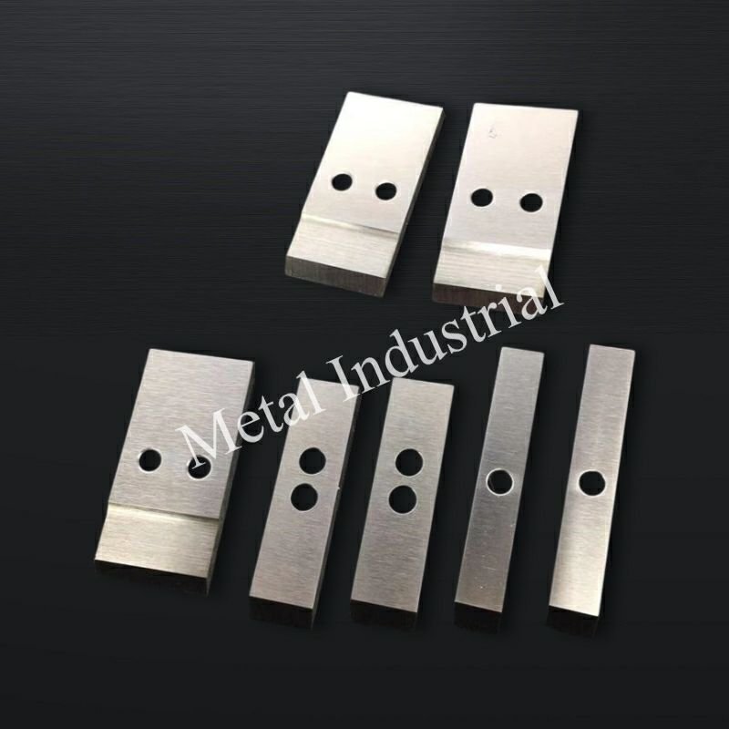
إن اختيار المادة الأساسية المناسبة هو العامل الأكبر الوحيد لإطالة عمر الخدمة في التطبيقات الكاشطة للمواد المملوءة بالزجاج. اعتبر اختيار المادة بمثابة تحديد “الحد الأقصى” لعمر الشفرة بين عمليات التجليخ، بينما تحدد الطلاءات وطريقة الإعداد مدى اقترابك من هذا الحد الأقصى.
خيارات كربيد التنجستن
للحصول على أقصى مقاومة للتآكل الكاشط، يأتي كربيد التنجستن (بما في ذلك السكاكين ذات الأطراف الكربيدية) في المقدمة. وتتحمل أطواره الكربيدية الصلبة الاحتكاك الناتج عن القطع والانزلاق ضد المصهور المحمل بالألياف، خاصة في دورات التشغيل الطويلة والمستقرة حيث يتم التحكم في المحاذاة بشكل جيد. والمقايضة هنا هي انخفاض متانة الكسر: ففي ظل الضغط الزائد، أو عدم المحاذاة، أو الصدمات أثناء بدء التشغيل، يمكن أن تتعرض حواف الكربيد لتشظيات دقيقة. كما أن الكربيد لا يتحمل التلامس العنيف بين الشفرة والقالب.
لا يقتصر استخدام الكربيد على الشفرات فحسب—بل تعتمد العديد من وجوه القوالب وقطع التآكل المدرجة في عمليات تحبيب البولي أوليفين على الكربيدات الهندسية لإبطاء تشكل الأخاديد وتقليل تكرار عمليات إعادة التهيئة، كما ينعكس ذلك في محفظة قوالب التحبيب من Kennametal وطبقات تغطية أجزاء التآكل المخصصة لمقاومة الكشط/التعرية. انظر مناقشة التصليد السطحي أدناه ونظرة عامة من المورد حول حلول قوالب الكربيد في مجال البولي أوليفينات في المصدر التالي: قوالب التحبيب ومواد التآكل من Kennametal (تم الدخول إليه في 2026).
متى تختار شفرات الكربيد: دورات الإنتاج الطويلة بتركيبات ثابتة، والتحكم الدقيق في المحاذاة، والأولوية القصوى لأطول فترات ممكنة بين عمليات إعادة التجليخ أو تغيير الشفرات.
لفرق المشتريات التي تقارن بين الخيارات، يوضح هذا الدليل الداخلي حول “شفرات تحبيب البلاستيك ذات الأطراف الكربيدية” التطبيقات والمفاضلات في معالجة البلاستيك: نظرة عامة على منتج شفرات تحبيب البلاستيك.
صلب أدوات عالي الفاناديوم بتقنية ميتالورجيا المساحيق (PM)
يعمل صلب أدوات عالي الفاناديوم بتقنية ميتالورجيا المساحيق (PM) — الشبيه بـ CPM 10V/15V وعائلات الصلب عالي السرعة مثل M4 — على تشتيت كربيدات الفاناديوم الصلبة في مصفوفة دقيقة، مما يوفر مقاومة ممتازة للتآكل الاحتكاكي مع هامش متانة كبير مقارنة بالكربيد الكامل. في تطبيقات الألياف الزجاجية (GF) تحت الماء، تساعد هذه المتانة في مقاومة تشقق الحواف أثناء التلامس العابر أو الانحراف الطفيف في المحاذاة، مع الاستمرار في التفوق في العمر الافتراضي على صلب M2/D2 التقليدي.
توثق أوراق البيانات التمثيلية من Uddeholm التوازن بين مقاومة التآكل والمتانة:
- يظهر Vanadis 8 SuperClean مقاومة عالية جداً للتآكل الاحتكاكي في تطبيقات العمل على البارد مع متانة محسنة مقارنة بـ D2. انظر الورقة الفنية لـ Uddeholm Vanadis 8 (تم الدخول إليه في 2026).
- يوسع كل من Vanadis 23 و 60 عائلة صلب السرعات العالية بتقنية ميتالورجيا المساحيق (PM HSS) عالي المقاومة للتآكل، حيث يصل Vanadis 60 إلى أعلى مستويات مقاومة التآكل ضمن فئته وفقاً لمخططات Uddeholm المقارنة: فاناديس 60 سوبر كلين (تم الدخول إليه في 2026).
متى تختار صلب PM: عندما تحتاج إلى عمر افتراضي طويل بالإضافة إلى إمكانية إعادة شحذ موثوقة وحماية ضد التشقق. تجد العديد من خطوط الألياف الزجاجية (GF) تحت الماء أن صلب PM عالي الفاناديوم (high-V) هو الحل الوسط الأفضل من حيث التكلفة الإجمالية.
M2 و D2 كمعايير أساسية
يظل M2 و D2 من المعايير الأساسية الشائعة، ولكن توقع عمراً افتراضياً أقصر في تطبيقات الألياف الزجاجية (GF) بنسبة 10–40%. تعمل كربيدات الكروم في D2 على تحسين مقاومة التآكل مقارنة بصلب الأدوات البسيط، ومع ذلك فإن درجات PM عالية الفاناديوم (high-V) تتفوق عليه عادةً في ظل التآكل الشديد. يوفر صلب السرعات العالية M2 صلادة جيدة في درجات الحرارة المرتفعة، ولكنه يأتي بعد صلب PM عالي الفاناديوم والكربيد في مقاومة التآكل الاحتكاكي في البولي أوليفينات المملوءة بالزجاج. إذا كانت الميزانية تتطلب استخدام M2/D2، ففكر في استخدام الطلاءات الواقية وتقريب فترات الشحذ.
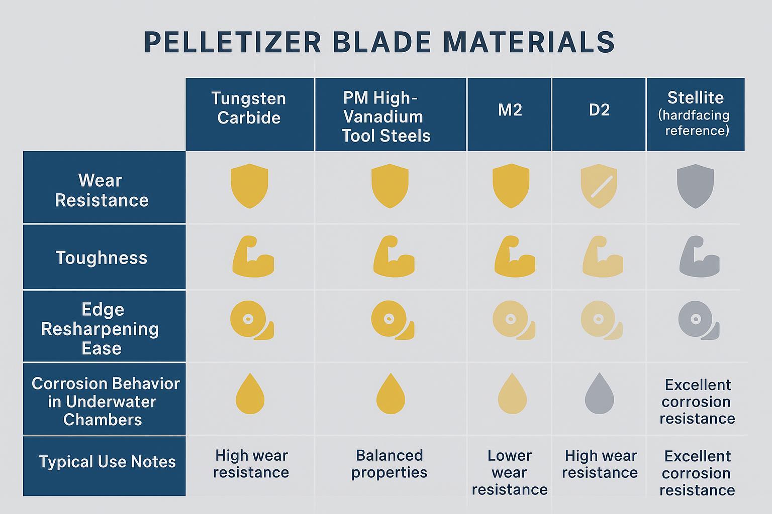
مقارنة سريعة لتسهيل اختيار المواد:
| مادة | Relative wear resistance | Relative toughness | Resharpening ease | Wet/corrosion behavior | Typical use note |
|---|---|---|---|---|---|
| كربيد التنغستن | أعلى | أدنى | Moderate (special wheels) | Good with proper binder; inert surface | Long, steady GF campaigns where alignment is tight |
| PM high‑V tool steels | عالية جدًا | Medium–high | High (standard grinding) | Good; benefits from protective PVD | Balanced choice for GF where chipping risk exists |
| د2 | واسطة | Medium–low | عالي | Moderate; may pit without protection | Budget baseline; pair with coating and tighter cadence |
| م2 | Medium–low | واسطة | عالي | Moderate; hot hardness helps | Shorter runs; step-up from basic tool steels |
| Stellite (hardfacing) | N/A (overlay) | غير متوفر | Reconditioned as surface | Good corrosion/erosion resistance | Die-face/wear overlays to delay grooving |
Surface engineering upgrades
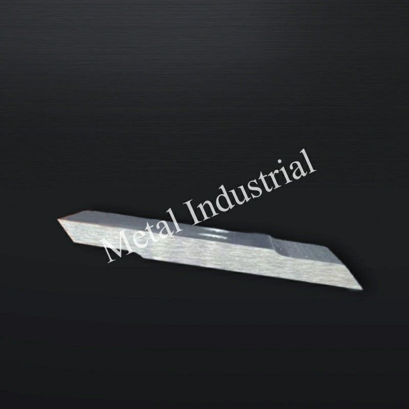
Surface engineering fine-tunes friction, corrosion behavior, and edge stability in wet, abrasive service. Two families dominate: thin-film PVD/CVD on blades and hardfacing overlays on dies and wear surfaces.
PVD/CVD coatings for wear control
In underwater chambers, coatings that manage both abrasion and corrosion perform best. Practical stacks often start with a corrosion-aware base (e.g., CrN) for adhesion and chemical stability, with a low-friction, wear‑resistant top (e.g., DLC variants or TiAlN depending on grind and temperature). Industry leaders note PVD’s role in harsh, corrosion/erosion-prone environments; for example, Oerlikon reports coating solutions for demanding wet service applications in its investor and annual communications: Oerlikon investor presentation on advanced PVD applications (2024) (تم الدخول إليه في 2026).
Ionbond highlights Tribobond series for corrosive/wear service and describes layer strategies, including pre‑treatments, that support durability in wet environments: Ionbond coating families for corrosive environments (accessed 2026). While not blade‑specific, these sources align with field experience in wet pelletizing chambers.
Use thin films (≈2–4 μm) on cutting edges to preserve geometry and allow controlled resharpening. Always confirm wheel spec, coolant, and feeds with your coater to avoid delamination during grinding.
Hardfacing overlays (e.g., Stellite)
Hardfacing protects the surfaces that must not wear fast—primarily the die face and any wear rings or inserts around the cutting zone. Cobalt‑based Stellite and tungsten carbide overlays are common to slow groove formation from glass fiber abrasion and micro‑entrained particulates. Kennametal’s Conforma Clad documentation describes Stellite 720 and WC-based overlays for abrasion/erosion control in severe industrial environments: Kennametal Conforma Clad — slurry-based cladding overview (تم الدخول إليه في 2026).
Coating and sharpening compatibility
- Keep coatings thin and uniform near the edge; avoid overly thick CVD films on sharpened edges unless validated for regrind.
- Coordinate sharpening parameters (wheel type, grit, coolant, pressure) with the coating vendor. Some DLC stacks prefer specific wheel chemistries and low-pressure passes.
- Recoat scheduling should align with your sharpening cadence; track edge geometry so the film is renewed before functional thickness drops below target.
Match blade and die plate
Proper pairing prevents the vicious cycle of grooves → tails → more pressure → faster wear.
Hardness pairing and metallurgy
Avoid extreme hard–hard pairings that risk scoring both components. A slight hardness offset and compatible metallurgies help the system wear in a controlled way. In practice, this means combining a wear‑resistant blade substrate (carbide or PM high‑V) with a die face whose finish and flatness are maintained meticulously, using hardfacing where appropriate. Where available, follow your OEM’s hardness and material pairing guidance rather than adopting generic numbers.
Die-face finish and flatness
Die-face condition is a top predictor of fines and tails. Grooves act like tracks that pull the blade edge, raising load and creating uncut whiskers. Keep the die face flat and smooth; recondition (grind/polish) before grooves propagate. Davis‑Standard’s troubleshooting guidance links poor die-face condition to pellet defects and recommends surface restoration as a corrective action. See: Davis‑Standard troubleshooting for pellet quality issues (2021).
Underwater vs strand considerations
Underwater (die‑face in water) cuts the melt while it’s still soft, lowering mechanical cutting load compared to strand pelletizing—useful with glass-filled compounds that would otherwise punish blade edges when fully solid. Plastics Technology’s overview of underwater pelletizing issues reinforces that water management and temperature balance are central to quality and longevity in these systems: Plastics Technology — mitigating and troubleshooting underwater pelletizing (2020).
For further reading on underwater-specific blade considerations, see this internal overview: underwater pelletizer blades choices guide.
Setup for glass-filled runs
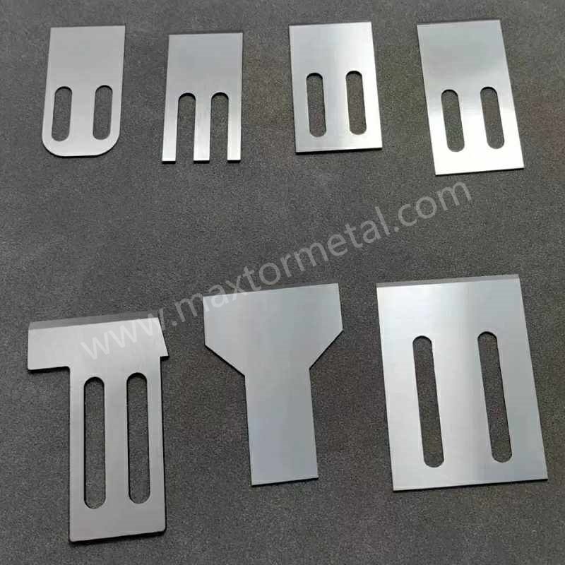
Safety & validation note: Follow your pelletizer OEM’s lockout/tagout and service procedures for any blade change, hub adjustment, or die-face reconditioning. Treat OEM settings as the governing reference. For coated blades, confirm the coating supplier’s approved grinding wheel, coolant, and pass strategy before resharpening to reduce delamination risk.
Dialing in contact, clearance, speed, and thermal balance is where many plants win or lose the fines battle. A small change in one variable can ripple through cut quality and wear rates—so document settings and change only one thing at a time. How do you know which lever to pull first? Start where risk is highest: contact pressure and alignment.
Contact and clearance control
- Set blade advance to achieve clean slicing with the lightest consistent contact. Excess pressure accelerates die-face grooving, especially with glass fibers.
- Verify flat, even contact across the arc. Uneven contact produces localized wear tracks and chipping.
- If your system supports it, use self‑aligning cutter hubs and position monitoring to maintain consistent contact through thermal expansions and minor runouts. MAAG’s catalog covers MAP (manual), EAC (electronic), and other hub designs that help maintain uniform blade‑to‑die positioning in production: MAAG EAC electronically adjustable pelletizer (2026) و MAAG MAP manually adjustable pelletizer (2024).
Speed, load, and heat
- Coordinate cutter speed with melt temperature and die pressure. Cutting too fast on a cool melt raises mechanical load, nudging edges toward rounding or micro‑chipping.
- If you observe “smearing” or tails at constant pressure, consider modestly adjusting cutter rpm or melt temperature to improve cut firmness without overloading the edge.
Cooling and water management
- Keep water temperature and flow within your OEM’s typical PP/PE range (often no need to exceed ~70 °C). Stability matters more than chasing a single number. Rapid quench can create voids or brittle skins that crumble into fines; too warm encourages chaining or stickiness.
- Filter the loop aggressively. Entrained grit (including glass fragments) re‑circulates to the die face and blades, deepening grooves.
- Watch water chemistry (pH, hardness) to limit corrosion that undercuts coatings or promotes deposit formation on the die face.
Maintenance that prevents fines
Illustrative example (not a performance guarantee)
A mid-to-high throughput underwater pelletizing line running PP with ~30% glass fiber begins to see a steady rise in fines and intermittent “tails,” even though the operator keeps increasing blade advance to maintain a clean cut. Inspection shows concentrated witness marks across the cutter arc and early groove formation on the die face.
What was changed (one lever at a time):
- Mechanical: verified hub self-alignment and corrected uneven contact so the blade sweeps the die face more uniformly.
- Process: reduced contact load to the lightest consistent setting, then fine-tuned cutter rpm to stop chatter without smearing.
- Water loop: improved filtration discipline (more frequent element changes and closer ΔP tracking) to reduce recirculated grit.
- Wear parts: switched from a baseline tool steel to a tougher, wear-resistant substrate (often a PM high-vanadium grade in this duty), and used a thin, corrosion-aware PVD stack validated for regrinding.
How success was judged:
- Fines trend stabilized (by sieve checks) and tails became visually rare.
- The required blade advance per shift stopped “creeping up,” indicating slower edge rounding.
- Die-face groove growth slowed, extending the interval before reconditioning.
Note: Your results will depend on formulation, throughput, cutter hub design, die-face metallurgy/finish, and water chemistry. Use the KPI table above to validate changes and document your own settings window.
Preventive routines turn unpredictable chipping and grooving into scheduled touch‑ups. Here’s the deal: don’t wait for fines ppm to spike—use visual and positional indicators to trigger actions earlier.
Inspection and sharpening cadence
Define your sharpening cadence by tracking hours, throughput, and fines ppm. PM high‑V steels often stretch intervals versus M2/D2 in GF service; carbide can run longest if alignment is excellent. Use the lightest practical grind to restore edge geometry and keep coating stacks intact when applied, and plan recoating on a multiple of your sharpening interval. For safe, step-by-step changeovers and service, reference this internal SOP: how to replace pelletizer die face blades safely and efficiently.
Alignment checks and self-aligning hubs
Confirm even contact across the arc at every planned stop; any concentrated witness marks signal misalignment. Verify self‑aligning hub function where equipped; worn pivots or springs defeat constant-pressure intent and drive localized grooving. OEM literature on underwater systems emphasizes these mechanisms because they stabilize blade position under thermal and hydraulic loads: MAAG underwater pelletizing systems category (تم الدخول إليه في 2026).
Diagnose wear modes and fixes
Common patterns tell you what to adjust next.
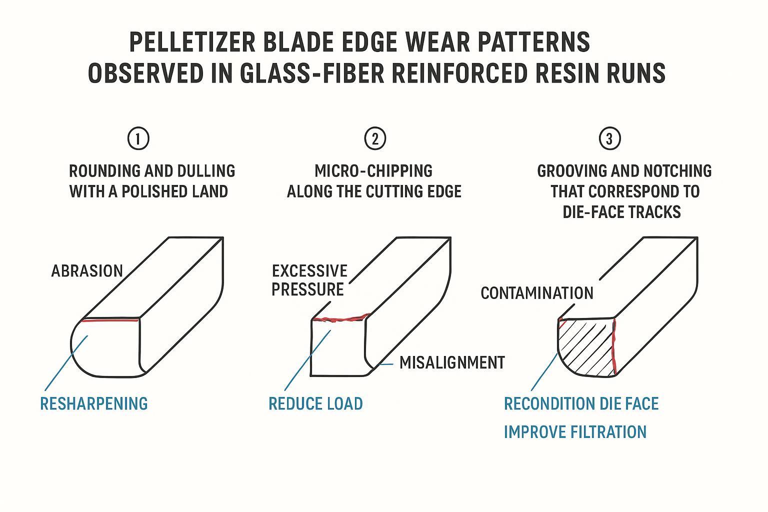
Rounding/polished land typically calls for a slight increase in advance or a resharpen, and sometimes a small rpm or melt-temperature adjustment. Micro‑chipping points to excessive contact pressure or misalignment; reduce load, verify alignment, or select a tougher substrate or different thin‑film stack. Grooving/notching is a die‑face and filtration story first—recondition the face, improve filtration, confirm even contact, and revisit your hardfacing/coating plan.
الخاتمة
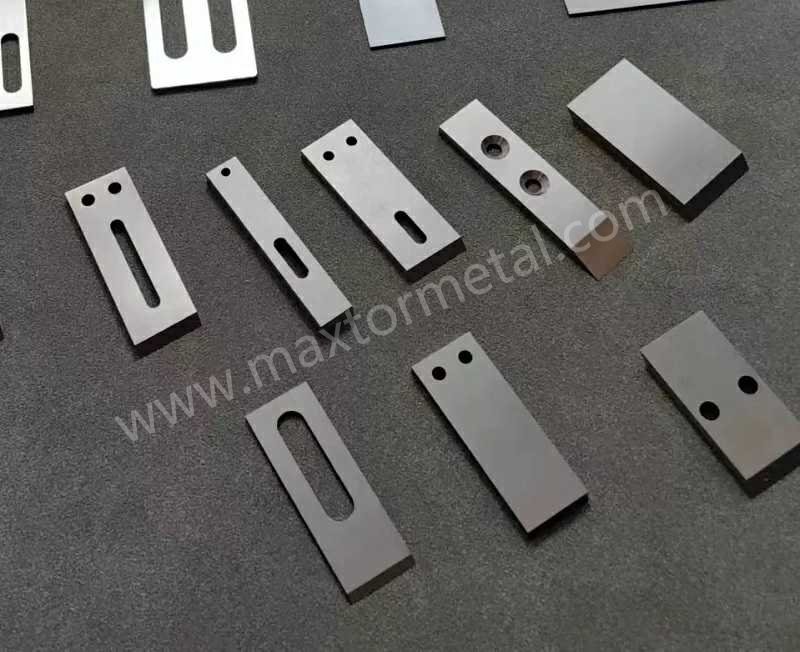
Abrasive glass fibers punish edges and die faces—but with the right substrate, surface engineering, and disciplined setup/maintenance, you can push longer, steadier campaigns at lower cost per ton. In practice, the winning combo for many underwater PP/PE lines is PM high‑vanadium steel or carbide blades, thin corrosion‑aware PVD stacks where appropriate, immaculate die‑face condition, and alignment systems that hold contact steady.
Checklist — choices that extend blade life and cut fines
- Material: choose carbide for maximum wear life with tight alignment, or PM high‑vanadium steel for toughness plus long life in GF duty.
- Coatings: consider CrN‑based stacks with low‑friction tops; keep films thin and confirm regrind parameters with the coater.
- Blade–die pairing: avoid extreme hard–hard combos; maintain die-face flatness/finish; apply hardfacing where grooves tend to start.
- Setup: set the lightest consistent contact; balance cutter rpm with melt temperature; stabilize water temperature/flow and filtration.
- Maintenance: define sharpening cadence by throughput and fines ppm; verify self‑aligning hub function; diagnose wear patterns early and act.
Tommy Tang is a Senior Sales Engineer at Nanjing METAL with 12 years of experience supporting underwater (die-face/water-ring) pelletizing operations and wear-part selection for abrasive, glass-filled compounds. Credentials: CSE, CME, Six Sigma Green Belt, PMP.
Method note: Recommendations in this guide prioritize OEM manuals, metallurgical datasheets, and observable wear modes (rounding, chipping, grooving). Always validate final blade–die pairing, coating stack, and grinding parameters with your pelletizer OEM and coating supplier.
Further reading and sources
- OEM troubleshooting on pellet defects and die-face condition: Davis‑Standard — troubleshooting common pellet quality issues (2021).
- Underwater system tuning and issues: Plastics Technology — mitigating underwater pelletizing issues (2020).
- Carbide die/wear surface approaches: Kennametal — pelletizing dies overview.
- PM high‑V steels and wear data: Uddeholm — Vanadis 8 technical sheet و فاناديس 60 سوبر كلين.
- PVD stacks in harsh, wet service: Oerlikon — investor presentation on advanced coating applications (2024) و Ionbond — coating families for corrosive environments.

 English
 Spanish
 Italian
 French
 Portuguese
 Russian
 German
 Arabic
 Hindi
 Vietnamese
 Indonesian
 Japanese
 Korean
ردود 4
I think this site has some very superb information for everyone : D.
شكرًا!
Nice post. I be taught something more difficult on totally different blogs everyday. It is going to always be stimulating to read content material from other writers and practice just a little something from their store. I’d want to use some with the content material on my weblog whether you don’t mind. Natually I’ll give you a hyperlink in your net blog. Thanks for sharing.
Thank you. Of course you can.