High‑filler masterbatch (glass fiber, CaCO3, talc, TiO2) is unforgiving on rotary cutters. Hard particulates plough the edge, accelerate rounding and micro‑chipping, and magnify any error in clearance, run‑out, or parallelism. The result is rising fines, tails, and unstable pellet geometry that drags down throughput and downstream yield.
This guide focuses on extending life, reducing fines/tails, and stabilising pellet shape through the entire chain: materials, coatings, edge geometry and finish, set‑up tolerances, metrology, maintenance windows, and a simple ROI model. We use SI units throughout and present practical ranges that should be validated against your specific pelletiser OEM manual.
Conclusiones clave
- Target uptime first: a disciplined tolerance stack (clearance, run‑out, parallelism) typically lifts mean time between regrinds/changes (MTBR) by ≥40% while holding fines ≤0.5% once stabilised.
- For abrasive duty, PM tool steels at HRC ~60–64 or carbide inserts with a controlled hone outperform D2/M2 in wear while protecting against micro‑chipping.
- Prefer thin, tough PVD coatings (TiAlN/TiN) or DLC where low friction is needed; pair coatings with an edge hone of 5–25 µm and a face finish Ra <0.2 µm.
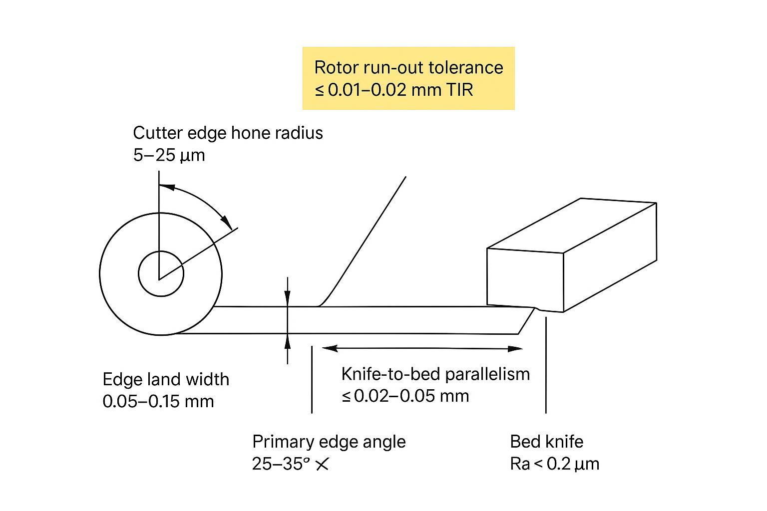
- Start clearance at 0.05–0.15 mm for high‑filler lines; hold rotor run‑out to ≤0.01–0.02 mm and knife‑to‑bed parallelism to ≤0.02–0.05 mm; verify with 0.002 mm‑class indicators.
- Lock in documentation: traceable materials/heat‑treat/hardness/tolerance reports and a regrind log are non‑negotiable for predictable cost‑per‑tonne.
Failure modes in high-filler duty
Abrasive wear mechanisms
Abrasive fillers embed and slide at the tool–polymer interface, eroding the primary edge and widening the land. As the edge radius grows, shear transitions toward crushing, which elevates cutting forces and fines. PM steels with dense vanadium carbides resist this rounding far better than D2; Crucible’s CPM‑class data document markedly higher abrasion resistance versus D2 in ASTM testing, with typical hardness windows of 60–65 HRC for these PM grades (see Crucible CPM 10V technical data).
Micro-chipping and impact factors
Misalignment, run‑out spikes, or hard particulate clusters cause intermittent impacts that initiate micro‑fractures along the edge. Excessively sharp, un‑honed edges are most vulnerable. A deliberate micro‑hone (5–25 µm) supports the cutting wedge and suppresses micro‑chipping at minimal penalty to sharpness; this range aligns with cutting‑tool best practice explained by Sandvik Coromant’s edge‑preparation guidance.
Thermal and corrosion effects
Insufficient strand drying and recirculating fines promote smearing and thermal spikes that soften edges and foul the land. OEM literature for strand pelletisers repeatedly ties residual moisture and abrasive duty to premature wear and dust generation; for example, MAAG’s strand pelletiser brochures highlight drying/handling as key to cut quality (see MAAG PRIMO series brochure, 2024, qualitative guidance).
Materials and hardness choices
D2/M2 tool steels
Conventional D2 (high‑carbon, high‑chromium) remains common for general polymers but struggles in high‑filler abrasion. Hardenability to ~58–62 HRC is typical. M2 offers hot‑hardness benefits but still lags PM steels for abrasive wear life.
PM steels for abrasive loads
Powder‑metallurgy grades like CPM 10V increase vanadium carbide volume, delivering markedly higher wear resistance at HRC ~60–64 while retaining usable toughness. For abrasive masterbatch, CPM 10V is a pragmatic starting point (Crucible CPM 10V).
Carbide and bed-knife pairing
Tungsten carbide (WC–Co) inserts shine under extreme abrasion. K20–K30‑equivalent grades typically test around HRA 90–92 with 6–10% Co, well suited to cutting filled polymers; see vendor overviews such as Hyperion’s Tiger•carbide grades (2023). Pair very hard rotors (PM/carbine) with bed knives in a slightly lower HRC band (≈58–62) to avoid brittle damage transfer. Label this as industry practice to be validated per OEM.
Coatings and edge support — boosting rotary cutter durability in high‑filler masterbatch
TiN/TiAlN trade-offs
Thin, tough PVD layers extend life without overly dulling the edge. TiN (≈1–5 µm; ~2300 HV; moderate COF) is versatile; TiAlN (≈2–6 µm; typically harder with stronger hot‑hardness) often outlasts TiN in heat‑prone runs. For representative, publicly posted coating specs, see Ionbond TiN (PVD) y Ionbond TiAlN (PVD) (typical thickness ranges and application notes vary by deposition route and tool geometry).
DLC for low friction
Diamond‑like carbon (a‑C:H) reduces friction dramatically (COF ~0.05–0.2 at ≈1–3 µm) and can lower fines where polymers tend to smear or stick. In PP/PE + CaCO₃ lines, DLC is most useful when pickup/smearing is a repeatable issue and cut temperatures are controlled; when heat is elevated (poor drying, heavy recirculating fines, or aggressive contact), nitrides like TiAlN are often the safer default. See Ionbond DLC (PACVD) y Oerlikon Balzers BALINIT C (DLC).
Edge prep and surface finish
Polymer cutting rewards a keen but supported edge. Start with a micro‑hone radius of 5–25 µm, a land width of 0.05–0.15 mm, and finish the cutting face to Ra <0.2 µm. For PP/PE with CaCO₃, a slightly larger hone within this range can reduce micro‑chipping when run‑out or filler agglomerates create intermittent impacts, while an overly large hone may raise cutting force and fines—so adjust in small steps and confirm with fines and pellet‑geometry data. These values stem from cutting‑tool practice and polymer‑cutting field experience; verify against your process targets.
Set-up and tolerances
Getting the tolerance stack right is the single best lever for rotary cutter durability in high‑filler masterbatch. Below are practice‑based starting windows that should be validated per OEM model and chamber size. These are also practical phrases to standardize on your SOPs if you want to target “run‑out tolerances pelletizer” alignment across sites.
Quick troubleshooting map (symptom → likely cause → what to check)
| Symptom on PP/PE + CaCO₃ lines | Causa probable | What to check first |
|---|---|---|
| Fines rising steadily over days | Edge rounding + clearance drift | Clearance setting, witness mark evenness, fines sampling method |
| Sudden fines spike after a change | Chips/burrs under seats; clamp distortion | Seat cleanliness, clamp torque repeatability, run‑out (TIR) |
| Periodic “tail” pattern (cyclic) | Run‑out or eccentric mounting | Run‑out at mounting diameter, hub/seat damage, indicator setup |
| Uneven pellet length across strands | Knife‑to‑bed parallelism error | Parallelism end-to-end and mid-span under torque |
| Smearing/pickup on edge/land | Moisture/poor drying; heat spikes | Strand drying performance, recirculating fines, cooling and cleanliness |
| Micro‑chipping on edge | Impact from misalignment or agglomerates | Hone size, run‑out spikes, clearance too tight for current truth |
Clearances and contact method
Begin with knife‑to‑bed clearance in the 0.05–0.15 mm range for abrasive compounds. For PP/PE with CaCO₃ (common in high‑filler masterbatch), the lower end of this window often helps keep a clean shear as the edge rounds—but only if run‑out/parallelism are tightly controlled and the knife seats are spotless. Tighter clearances sustain clean shear as edges wear but demand high rotor truth and bed flatness. Avoid hard “rubbing contact” as a normal condition; aim for a light, even skim that produces a consistent, bright witness across the length during set‑up, then back off to the target clearance.
Neutral, spec‑led example (MAXTOR METAL): When specifying traceable cutters and bed knives for high‑filler lines, engineers often request PM tool‑steel rotors and optional carbide inserts, supplied with full dimensional and heat‑treat documentation. As an example, MAXTOR METAL PM/carbide rotary and bed knives can be ordered to the following verifiable parameters for a strand pelletiser:
- PM rotor knife: CPM‑class grade (e.g., CPM 10V‑equivalent), hardness HRC 60–63; micro‑hone radius 0.005–0.02 mm; cutting‑face Ra <0.2 µm.
- Bed knife: tool steel at HRC 58–62 (or WC–Co insert per application), flatness/parallelism report ≤0.02–0.05 mm.
- Set‑up targets (to validate per OEM): clearance 0.05–0.15 mm; rotor run‑out (TIR) ≤0.01–0.02 mm; knife‑to‑bed parallelism ≤0.02–0.05 mm.
- Documentation pack: material certificate, heat‑treatment report, hardness scan, dimensional tolerance report, and batch trace code matching the serial on each blade.
This example is provided for specification context only; always reconcile with the machine manual and plant quality targets. For a deeper overview of strand‑cutting hardware and inspection practices, see MAXTOR METAL’s masterbatch pelletizer blades guide.
Geometry, run-out, parallelism
- Rotor run‑out: hold ≤0.01–0.02 mm TIR at the mounting diameter. Correct any stack‑up from hub burrs, chips on seats, or distorted clamps.
- Knife parallelism: ≤0.02–0.05 mm across the working length; verify at both ends and mid‑span under clamp torque.
- Edge angles: 25–35° primary edge angle is common for polymer strands; steeper angles add robustness against micro‑chipping but may raise cutting force.
Recommended metrology (example specifications)
| Instrument | Objetivo | Resolution/accuracy (SI) |
|---|---|---|
| Test indicator (e.g., Starrett 711 or Mahr MarTest) | Run‑out/parallelism checks | 0.002 mm graduation |
| Surface roughness probe | Verify Ra on cutting face/land | ≤0.05 µm resolution |
| Torque wrench (±3%) | Repeatable clamp load on knife seats | ±3% of set torque |
If you need example indicator specs, one representative page is Starrett’s 711MFSZ test indicator.
Cooling and cleanliness
Dry, clean strands reduce smearing and heat spikes at the cut. Maintain efficient dewatering/air‑knife performance and keep knife seats immaculate. OEM brochures emphasise drying and handling as levers for fines and tool life in strand pelletisers; see the qualitative guidance in MAAG’s M‑ASG literature.
Maintenance, life, and ROI
Regrind windows
Define objective triggers to avoid running blunt or chipped edges that inflate fines and accelerate wear elsewhere:
- Wear‑land/edge recession reaching ~0.2–0.5 mm.
- Sustained fines above 0.5% by weight over a defined production lot.
- Alignment drift outside run‑out/parallelism targets.
Log each grind’s material removal to manage remaining life, and always preserve geometry (edge angle, land width, hone radius, Ra target) on regrind.
Traceability and documentation
Require a pack that ties every blade to its manufacturing record: material certificate, heat‑treat report, hardness scan, coating batch (if any), dimensional tolerance report, and batch/serial trace code.
Cost-per-tonne model
Here’s a conservative, reproducible way to quantify gains while you pursue higher rotary cutter durability in high‑filler masterbatch.
Inputs (example):
- Baseline blades: D2 at HRC 60; cost: €220 each; life: 3,000 kg between regrinds; 3 regrinds; changeover downtime cost: €600 per event; fines: 1.0%.
- Upgrade: PM steel at HRC 61 with TiAlN; cost: €360; expected life multiplier 1.5–2.5× (use a conservative band and validate with your own A/B data; PM grades like CPM‑class steels show materially higher abrasion resistance than D2 in supplier wear charts); 4 regrinds; downtime unchanged per event; fines: 0.5%.
Worked result (per 30,000 kg campaign):
- Baseline blade spend + regrinds: assume 10 cycles → ≈€2,200 blades + €X regrinds; downtime 10×€600 = €6,000; yield loss from fines = 1.0% of material value (insert your €/kg).
- PM upgrade: ≈4.5 cycles → ≈€1,620 blades + €X regrinds; downtime 4.5×€600 = €2,700; yield loss halves at 0.5%.
Even before valuing the fines reduction, the MTBR lift (roughly ≥40% in most stabilised lines) cuts downtime materially; include sensitivity bands for life multiplier (±20%) and fines (±0.2 pp) to set realistic expectations. Replace € with your local cost basis; the structure carries over.
A/B trial and log checklist (minimum viable)
- Run at least 2–3 full change/regrind intervals per blade option (baseline vs. upgrade) on the same line, with identical geometry and set‑up method.
- Record per interval: material (polymer + filler type/loading), throughput, strand count, cooling/drying notes, knife‑to‑bed clearance setting, measured run‑out (TIR), knife‑to‑bed parallelism, edge hone (µm), cutting‑face Ra (if available), fines % (by weight) with sampling method, pellet geometry notes, downtime minutes per change, and cumulative regrind stock removal.
- Evaluate: MTBR (hours or tonnes), fines % trend, and cost‑per‑tonne using the same downtime and material-value basis.
Conclusión
- Procurement parameters to specify and verify: steel or carbide grade; final hardness band; edge geometry (angle, hone radius, land width); cutting‑face Ra; coating type and thickness; knife‑to‑bed clearance target; rotor run‑out and knife parallelism limits; delivered inspection pack (material, heat‑treat, hardness scan, dimensional report, batch/serial).
- Practical steps to stabilise cut quality and uptime: hold clearance at 0.05–0.15 mm, run‑out ≤0.01–0.02 mm, and parallelism ≤0.02–0.05 mm; use 5–25 µm hone and Ra <0.2 µm; dry strands thoroughly; keep seats immaculate; verify with 0.002 mm‑class indicators and a torque routine.
- Trial plan to validate life and cost‑per‑tonne gains: run paired A/B lots over multiple regrind cycles using your current blade vs a PM or carbide upgrade with identical geometry; log MTBR, fines %, pellet shape tolerance, and downtime; aim for ≥40% MTBR improvement while holding fines ≤0.5%.
Autor
Tommy Tang is a Senior Sales Engineer at Nanjing METAL Industrial with 12 years of experience supporting polymer pelletizing and industrial blade applications. Certifications: CSE, CME, Six Sigma Green Belt, PMP.
Data notes & disclosures
- Numeric ranges in this guide (e.g., clearance, run‑out, parallelism, hone radius, and surface finish targets) are presented as practical starting windows based on vendor datasheets and common field practice. Always validate and prioritize the tolerances and adjustment procedure in your specific pelletizer OEM manual.
- The MAXTOR METAL section is included as a neutral, specification-led example to illustrate what a traceable procurement/inspection package can look like; it is not a performance guarantee.
- Any life multipliers and ROI outcomes depend strongly on polymer family, filler type/loading, chamber size, strand count, line speed, cooling/drying effectiveness, and set‑up repeatability. Confirm by running a controlled A/B trial over multiple change or regrind cycles.
References (selected)
- Crucible Industries — CPM 10V datasheet (PM tool steel hardness window and wear-resistance context)
- Crucible Industries — D2 datasheet (baseline tool steel hardness window)
- Sandvik Coromant — Edge preparation guidance (hone size trade-offs)
- Ionbond — TiN (PVD) overview y TiAlN (PVD) overview (typical thickness/application notes)
- Ionbond — DLC (PACVD) overview (low-friction coating notes)
- Oerlikon Balzers — BALINIT C (DLC) (DLC coating family overview)
- MAAG — PRIMO series brochure y M‑ASG literature (qualitative drying/handling guidance)
- Starrett — 711MFSZ test indicator (0.002 mm‑class indicator example for run‑out/parallelism checks)