

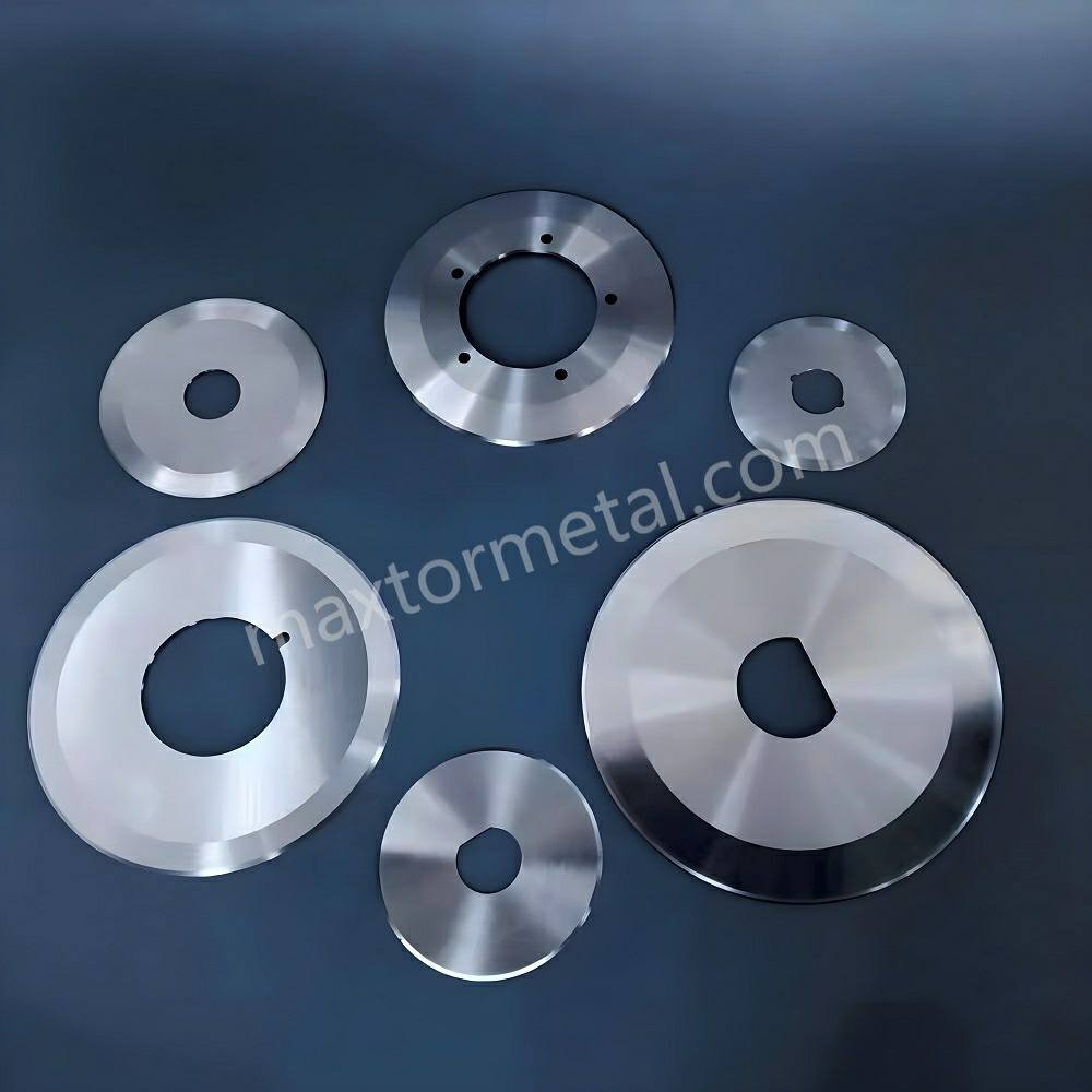
- Portée : couteaux circulaires en carbure pour le refendage d'électrodes et de séparateurs Li-ion
- Objectifs : contrôle des bavures en vitesse, durée de vie prolongée, temps de fonctionnement et TCO
- Public cible : responsables de production, superviseurs d'équipements, responsables de maintenance
Portée et limites (à lire en premier) : Ce rapport fournit des conseils pratiques de mesure et de contrôle de procédé pour le refendage d'électrodes et de séparateurs Li-ion. Les valeurs cibles, les réglages et la cadence d'inspection dépendent de la conception de votre équipement (architecture de refendage par cisaillement/score), du système de matériaux (Cu/Al, revêtement, type de séparateur), de la vitesse de ligne et de la capacité de mesure. Validez tout changement par des essais contrôlés sur votre ligne et respectez vos procédures internes de sécurité et de qualité.
Comment ce guide a été élaboré : Les recommandations présentées ici sont compilées à partir de problèmes récurrents sur le terrain constatés lors du support après-vente (pics de bavures, poussière/débris excessifs, instabilité), ainsi que des enseignements tirés des boucles de dépannage qui lient les fenêtres de configuration (jeu/pincement/angle de pointe, TIR/parallélisme, stabilité de la tension) à des résultats mesurables. Considérez les plages et les exemples comme des points de départ pour des essais contrôlés, et non comme des réglages universels.
Indicateurs de longévité pour la durée de vie des couteaux de refendage en carbure
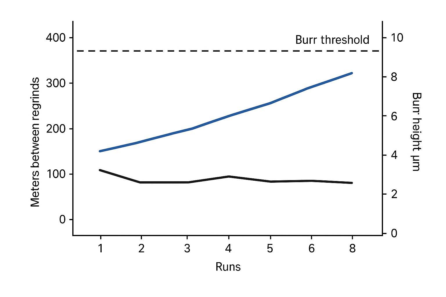
C'est dans cette section que les équipes définissent généralement leur hauteur de bavure de refendage d'électrode seuil et le convertissent en un déclencheur de maintenance (mètres coupés, nombre de réaffûtages ou inspection basée sur le temps).
La longévité dans le refendage d'électrodes/séparateurs ne se résume pas à “ combien de temps avant que le couteau ne paraisse émoussé ”. En production, c'est la capacité à maintenir la hauteur de bavure stable et la qualité des bords constante d'une bande à l'autre tout en maintenant la vitesse de ligne et des changements d'outils prévisibles.
Pour que la discussion reste pratique, cette section définit les KPI fondamentaux, la manière de les échantillonner et les données à enregistrer afin que votre équipe puisse relier les résultats à la configuration et au matériel.
KPI et objectifs
Utilisez trois groupes de KPI. Ensemble, ils décrivent la qualité des bords, la durée de vie et l'impact commercial.
- KPI de qualité des bords (principaux critères d'acceptation)
- Hauteur maximale de bavure (µm) par bande et par côté (côté opérateur / côté entraînement).
- Taux de dérive des bavures: variation de la hauteur de bavure par X mètres.
- Décollement des bords / éclatement du revêtement: à enregistrer sous forme de taux (événements par rouleau) ou de mesure de largeur si vous la mesurez déjà.
La tolérance aux bavures dépend du risque lié à la conception de votre cellule, de la capacité du système de mesure et de l'étape suivante pour le bord (bobinage ou empilage). Comme point de repère initial, de nombreuses discussions sur le refendage de batteries citent des objectifs de bavure de l'ordre du micron (chiffre unique) ; par exemple, BatteryDesign souligne que les bavures et l'ondulation peuvent contribuer au risque de court-circuit et à l'instabilité du procédé lors du bobinage en aval, et documente comment les tendances de jeu et de géométrie peuvent orienter le procédé vers des bavures ou du décollement dans différentes zones de l'électrode.
Points clés à retenir: Un “ bon ” chiffre de durée de vie de couteau n'a aucun sens si la hauteur de bavure ne reste pas inférieure à votre seuil pendant tout l'intervalle.
Exemples d'objectifs et format de rapport (points de départ)
Utilisez vos limites de risque en aval pour définir les seuils d'acceptation finaux. Le tableau ci-dessous montre comment les équipes rapportent couramment les objectifs par matériau et par régime de vitesse. Les valeurs sont des exemples et doivent être validées sur votre propre ligne.
| Application | Régime de vitesse de ligne typique (m/min) | Statistiques de rapport recommandées | Exemple de cadre d'acceptation (bavure et dérive) |
|---|---|---|---|
| Refendage d'électrodes standard (électrodes Cu/Al) | 40–120 | médiane + P75 + max par bande/côté | Définissez une limite maximale de bavure (µm) ainsi qu'une limite de dérive (∆µm par X mètres). Déclenchez l'inspection/le réaffûtage lorsque la dérive augmente ou que le maximum approche de la limite. |
| Lignes de batteries de VE à grande vitesse | 120–200+ | médiane + P75 + max + pente de tendance | Resserrez la cadence d'échantillonnage autour des changements de rouleaux et des rampes ; suivez la pente de tendance pour éviter de longues pertes de matière. |
| Refendage de séparateur | 200–600 | médiane + P75 + max + taux d'événements de défaut | En plus des bavures, suivez les événements de débris/poussière et les défauts de manipulation de la bande ; vérifiez la répétabilité des mesures à vitesse plus élevée. |
Plages d'épaisseurs de feuille typiques utilisées dans la planification (exemples) :
- Feuille de cuivre : 6–12 µm (LIB standard), 8–12 µm (VE plus ancien/général), 3–6 µm (ultra-fin haute énergie)
- Feuille d'aluminium : 12–20 µm (cathode standard), 8–12 µm (haute densité d'énergie), 16–20 µm (grades plus anciens)
- KPI de durée de vie des couteaux (planification de la maintenance)
- Mètres coupés entre les réaffûtages (ou entre les rafraîchissements d'arête).
- Nombre de réaffûtages avant mise au rebut (nombre de cycles avant le diamètre extérieur minimal ou la limite géométrique).
- Changements non planifiés (nombre et cause racine).
- KPI de production (ce qui importe à la direction)
- Taux de rebut lié aux défauts d'arête (séparer le rebut “ dû aux bavures ” du rebut lié au revêtement/à la manipulation).
- Impact sur le TRS: minutes perdues par changement de couteau + minutes perdues par recherche de défauts.
Méthode d'essai et échantillonnage
Un rapport de longévité n'est crédible que si l'échantillonnage est répétable. Le but n'est pas de réaliser une étude de laboratoire parfaite, mais de produire des données décisionnelles exploitables par votre équipe.
Une méthode pratique qui fonctionne sur la plupart des lignes :
- Définir une méthode de mesure de référence (“ golden ”) pour la hauteur de bavure (microscopie optique hors ligne ou profilométrie si disponible), et un signal haute fréquence en atelier (tendance vision/laser en ligne, ou contrôle ponctuel standardisé).
- Transparence de la méthode (recommandée pour la traçabilité) : enregistrez le type/modèle d'instrument, l'objectif/grossissement (si microscopie), la résolution de mesure, la définition de l'emplacement d'échantillonnage (arête, face, côté revêtement), et votre fréquence d'étalonnage/vérification. À titre d'exemple de guide industriel, une présentation de Leica Microsystems note que IEEE 1625 (Section 5.3.6.2) recommande la mesure des bavures et la comparaison avec la limite de tolérance d'épaisseur du séparateur, et que l'inspection des bavures se fait normalement en observant les arêtes/faces des électrodes par microscopie optique.
- Liste de contrôle de reproductibilité minimale (recommandée) :
- Microscopie optique : objectif/grossissement, taille de pixel ou résolution de mesure, réglage de l'éclairage/contraste si pertinent, lieu de mesure (arête vs face ; côté revêtement vs côté feuille), et mesures répétées (par ex. 3 lectures par couloir et par côté).
- Profilométrie : longueur de balayage/définition du tracé, règle de filtrage (si utilisée), résolution de mesure, et balayages répétés.
- Cadence d'étalonnage/vérification (pratique) : vérifiez votre système de mesure après des changements d'outils majeurs (changement de couteau, retour de réaffûtage) et à une cadence fixe (par ex. hebdomadaire) afin que les données de tendance restent comparables d'une équipe à l'autre.
- Cadence d'échantillonnage:
- Lors du réglage : échantillonnez chaque couloir jusqu'à stabilisation.
- Après stabilisation : échantillonnez à intervalles fixes de bobines/mètres (par ex. tous les X mètres ou à chaque changement de bobine).
- Après toute intervention (nettoyage, changement de tension, changement de couteau) : répétez l'échantillonnage de réglage.
Exemples de cadences courantes (points de départ) :
- Contrôle de la hauteur de bavure : tous les 1–3 rolls, and whenever a material recipe change occurs.
- Microscope edge inspection: tous les 5–20 km accumulated slitting length (especially for ultra-thin copper foil).
- Knife edge cleaning: tous les shift or on any recipe change.
- Full knife inspection: tous les 20–100 km (or sooner if burr drift accelerates).
- Regrind/replacement decision: based on burr trend + dust increase and whether stable burr performance can be recovered after cleaning/adjustment.
Inspection frequency varies between plants; treat these as planning references and tighten/loosen based on your burr risk threshold, speed regime, and measurement capability.
- Lane strategy: sample edge quality on at least 3 lanes (edge, center, edge) so you can catch alignment/runout patterns.
For inspection strategy context, Robovision’s overview of burr detection in battery manufacturing is useful as a reminder that the goal is not only detection—it’s closing the loop fast enough to prevent long scrap tails.
Data logging and traceability
If you want burr stability and life improvements to survive shift changes, you need traceability that ties outcomes back to controllable inputs.
At minimum, log these fields for each run (or each changeover event):
Copy-paste logging template (minimum viable)
| Champ | Exemple | Pourquoi c'est important | Suggested frequency |
|---|---|---|---|
| Run ID / date / shift | 2026-05-12 / Shift B | Traceability across shifts | Every run |
| Knife ID / set ID | CK-240512-03 | Links outcomes to a specific knife set | Every run |
| Carbide grade family / coating | WC–Co (grade family A) / DLC | Separates wear vs pickup drivers | Every run |
| nombre de rebroyés | 5 | Life-to-retirement planning | Every run |
| Post-grind TIR (µm) | 8 µm | Predicts lane periodicity & burr spikes | After regrind / after install |
| Slitter station / shaft ID | Station 2 / Shaft A | Isolates machine-side issues | Every run |
| Spacer stack ID / condition | Stack-7 / cleaned | Repeating bad lanes often trace here | Every rebuild |
| Gap/overlap setting | 0.02 mm | Primary cut-mode control | Every setup/change |
| Toe-in / cant setting | +0.05° | Affects burr vs delamination | Every setup/change |
| Tip angle / bevel orientation | 55° / coating side | Geometry vs defect linkage | Every setup/change |
| Web tension by zone | Z1 25N / Z2 30N | Instability can dominate defects | Every run (or trend log) |
| Material (Cu/Al/separator) | Cu 8 µm / Lot 24A | Lot-to-lot variation | Every run |
| Line speed | 160 m/min | Speed regime changes defect window | Every run |
| Burr by lane (µm) | L1–L12 (max/median) | Acceptance & drift tracking | Per sampling cadence |
| Taux de dérive des bavures | +1 µm / 10k m | Early warning for changeover planning | Per sampling cadence |
| Edge defects / delamination | 2 events / roll | Complements burr-only view | Every roll / event |
| Scrap meters (edge-related) | 120 m | Business impact | Every run |
| Intervention notes | Cleaned / tension tuned | Links actions to outcomes | Every event |
You can paste this table into an Excel sheet or CMMS record and add your internal acceptance limits in a separate column.
- Knife identity: serial/ID, carbide grade family, coating (if any), edge geometry spec, current regrind count.
- Grinding history: last grind date, grind batch, measured TIR after grind, measured edge condition (pass/fail).
- Machine identity: slitter station ID, shaft ID, spacer stack ID.
- Paramètres de réglage: gap/overlap setting, toe-in/cant setting, tip angle/bevel orientation, contact pressure setpoint (if applicable), web tension by zone.
- Matériau: foil type (Cu/Al), thickness, coating type, supplier lot, separator type if applicable.
- Outcomes: burr height by lane, delamination events, scrap meters, meters cut since last regrind.
The advantage of traceability is speed: when burr spikes, you can immediately ask, “Is this a setup drift, a tension-zone issue, or a knife condition issue?”—instead of re-running a full DOE from memory.
Modes de défaillance
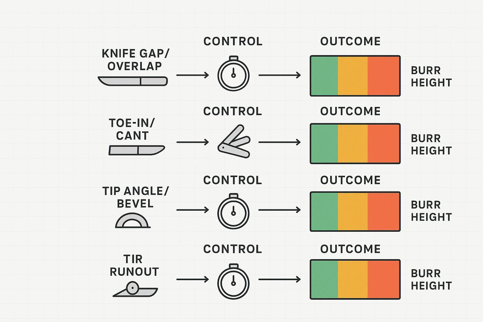
A useful longevity report doesn’t just list failure modes—it links them to what you can measure, what you can control, et what you should do next.
Built-up edge and adhesive pickup
In electrode and separator slitting, adhesive pickup can show up as a gradual increase in burr height, more dust/debris, or edge waviness that looks like a tension problem but isn’t.
Common contributors:
- Higher friction at the edge (surface condition, contamination, or coating mismatch).
- Process instability that makes the knife rub rather than shear cleanly.
- Cleaning that removes debris inconsistently (build-up becomes cyclical).
Controls that usually pay off:
- Keep cleaning and inspection cadenced, not reactive.
- Treat pickup as a process signal: when pickup increases, verify gap/contact and tension stability before blaming the material.
Micro-chipping and thermal cracks
Micro-chipping is typically a “setup + rigidity + edge strength” problem. Thermal cracking is often a “heat + cycling + surface condition” problem. Both shorten life because they turn a stable wear process into step-change burr spikes.
Practical triggers to check first:
- Runout (TIR) or parallelism drift → periodic burr variation by lane.
- Over-aggressive contact/overlap → edge loading and early chipping.
- Vibration or lane instability → chatter marks, intermittent burr spikes.
When you see chipping, the corrective action isn’t only “use a tougher knife.” It’s usually:
- verify metrology (TIR/parallelism/spacing),
- restore the original edge geometry at regrind,
- and remove the setup condition that creates impacts.
Burr–delamination linkage
Burr and delamination are often two sides of the same control problem: the line is operating outside the narrow window where the cut is clean.
BatteryDesign’s article on Slitter Burrs, Waviness and Delamination is a good reference for the directional tendencies many teams observe:
- Smaller tip angles tend to increase burr tendency.
- Larger tip angles (around and above ~60° in their discussion) tend to increase delamination tendency.
- In coated areas, very small gaps can bias toward burrs, while larger gaps can bias toward delamination.
In practice, the key is to define your acceptance window as burr threshold + delamination threshold, not just burr.
Matériaux et revêtements
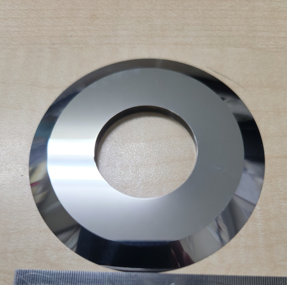
Carbide circular knives are usually chosen for one reason: keeping edge stability long enough to reduce changeovers without letting burrs creep upward.
WC–Co grades and toughness–wear balance
WC–Co (tungsten carbide–cobalt) grades sit on a trade curve:
- Harder / wear-focused grades can hold an edge longer in abrasive duty, but they’re more sensitive to setup shocks (chipping risk rises if TIR, spacing, or tension is unstable).
- Tougher grades tolerate vibration and small impacts better, but may wear faster in high-abrasion conditions.
A longevity report should therefore record grade family and then correlate it against:
- meters between regrinds,
- burr drift,
- and failure mode (pickup vs chipping).
DLC, TiCN, CrN trade-offs (vendor-reported)
Coatings are not universal “life multipliers.” They change friction, adhesion tendency, and how the edge behaves under heat.
A practical way to evaluate coatings on your line:
- Utiliser DLC candidates when pickup/adhesion and friction are the dominant failure signals.
- Utiliser TiCN candidates when abrasive wear dominates and your mechanical setup is already stable.
- Utiliser CrN candidates when corrosion/chemical exposure (cleaning, humidity) is non-trivial and you need a robust, general-purpose surface.
Whatever you test, bind it to your logging: coating type → burr stability → meters between regrinds → scrap.
Abrasive wear vs pickup/adhesion: when each tends to dominate
In modern electrode slitting, abrasive wear et material pickup are both common failure modes. Abrasive wear is typically driven by graphite, oxide particles, and coating dust—often more pronounced with high-Ni cathode systems, harder coatings, and high-dust conditions. Pickup/adhesion becomes more significant at higher line speeds, elevated edge temperatures, and with binder-rich coatings. In practice, many plants observe mixed wear behavior rather than a single dominant mechanism.
Use this as a simple decision frame:
- If burr rises slowly and dust increases gradually across most lanes → investigate abrasive wear drivers (dust control, coating abrasiveness, coating choice, edge strength).
- If burr rises in cycles with visible buildup or sudden spikes after ramps/recipe changes → prioritize pickup/adhesion controls (cleaning cadence, friction reduction, thermal stability, contact window verification).
- If you run long continuous campaigns → expect both to accumulate; manage by combining trend-based triggers with a fixed inspection cadence.
Practical coating selection frame (starting point)
| Dominant signal on your line | Primary risk | Coating candidate direction (starting point) | Preconditions (to avoid false conclusions) |
|---|---|---|---|
| Pickup/adhesion, edge buildup | Burr spikes, debris tails | DLC candidates | Stable TIR/parallelism, controlled tension transients |
| Abrasive wear, dust-driven dulling | Gradual burr drift | TiCN candidates | Setup window stable; dust control and web handling verified |
| Corrosion/chemical exposure from cleaning/humidity | Surface degradation | CrN candidates | Confirm cleaning chemistry and exposure conditions |
Note: Coating performance is line-specific. Evaluate candidates through single-factor trials and record outcomes in the logging template (burr trend, drift rate, meters between regrinds, scrap, and downtime).
Edge geometry pairing for Cu/Al and separators
You’ll usually need at least two geometry strategies:
- Cu/Al foil + coated electrodes: bias toward controlled shear with geometry that avoids coating breakout while keeping burr under the threshold.
- Séparateurs: bias toward low debris generation and stable web handling (tension and lane stability can dominate outcomes).
The rule is simple: do not reuse a geometry just because it “worked on foil.” Treat separators as their own process.
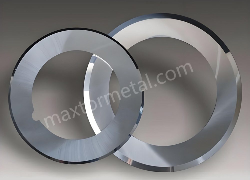
If you’re reviewing circular knife options and typical manufacturing tolerances, MAXTOR METAL’s couteaux et lames circulaires page is a starting point for the product category and customization scope.
Procédé et tolérances
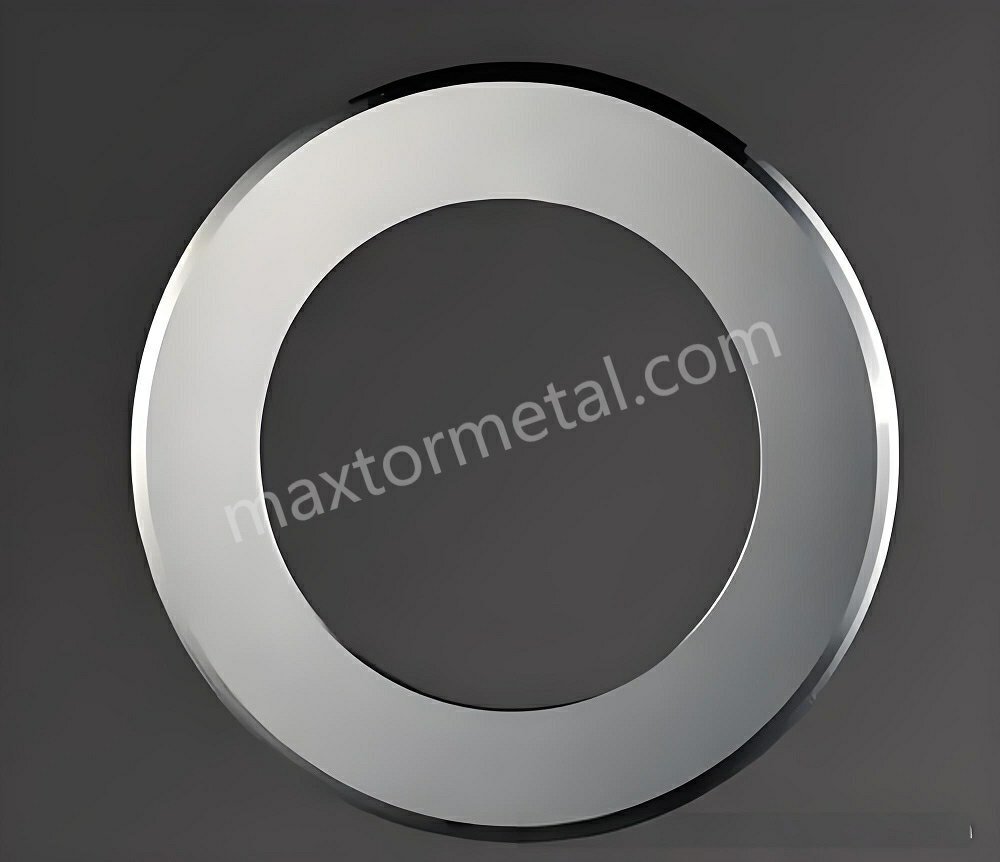
Longevity is heavily determined by whether the line stays inside your gap/toe-in/angle/TIR/tension windows.
Gap, toe-in, and tip angle windows
Treat these as coupled controls (your core gap and toe-in settings live here):
- Gap/contact (or overlap) sets how much the material is sheared vs rubbed.
- Toe-in/cant controls progressive shearing vs tearing/waviness.
- Tip angle/bevel shapes the burr vs delamination tendency.
BatteryDesign’s slitter burrs, waviness and delamination discussion describes the directionality many teams see in practice (e.g., too-strong toe-in trending to burrs; too-weak trending to delamination or waviness).
For general rotary shear setup principles (measurement and defect linkage), the Carolina Knife PDF on principles of shear splitting is a useful baseline reference.
TIR, parallelism, and spacing control
If you only measure one metrology item consistently, measure runout.
- TIR/runout (sometimes tracked as a slitter knife runout TIR spec after grinding and installation) shows up as lane-to-lane variability and periodic burr spikes.
- Parallélisme drift shows up as one side wearing faster and changing burr trends.
- Spacing/spacer stack issues show up as the same “bad lanes” repeating across runs.
Minimum practical checks:
- Dial-indicator check on knife OD after install and after regrind.
- Quick parallelism check (same indicator, repeatable reference surface).
- Spacer stack cleanliness and damage inspection before rebuild.
Web tension and lane stability
Edge quality and life both degrade when tension is unstable.
What to watch:
- If burr spikes coincide with tension-zone alarms or roll-change transients, you may have a control-loop issue rather than a knife issue.
- If waviness appears with stable burr, the root cause may be lane stability, not contact settings.
Treat tension as part of the cutting system. Your knife can’t compensate for oscillating tension at the cut point.
Maintenance and ROI
A longevity report becomes valuable when it changes scheduling and purchasing behavior—not just when it describes the past.
Regrind limits and inspection cadence
Define regrind limits in terms of both geometry and performance:
- Geometry limits: minimum OD, minimum land, minimum edge thickness, and any coating re-application rules.
- Performance limits: burr height approaching threshold, rising burr drift rate, or recurring lane-specific defects.
A practical cadence that works on many lines:
- Each shift: quick visual check + cleanliness check (pickup, discoloration, edge damage).
- Hebdomadaire: runout/parallelism verification on the slitter station.
- Each regrind: record post-grind TIR and balancing status, then reset the “meters since regrind” counter.
MAXTOR METAL’s own maintenance content on common round slitter blade wear issues is aligned with these basics (dulling, chipping/cracking, corrosion) and reinforces the practical point that grinding should preserve the original angle and avoid overheating.
Changeover planning and OEE impact
Knife changes cost more than labor. They create:
- lost minutes,
- elevated defect risk during re-thread and ramp,
- and extra verification cycles.
Two low-effort practices that improve OEE:
- Stage a “ready” knife set (verified TIR, cleaned spacers, documented geometry) to reduce changeover variability.
- Use your burr trend and meters-cut trend to schedule changes avant the threshold is hit, not after scrap starts.
TCO modeling with meters cut and scrap
This is the part most teams mean when they say slitter knife TCO: turning burr control and meters between regrinds into a cost-per-meter that procurement and operations can agree on.
Use a simple, auditable TCO model. You can refine it later.
Define:
- Knife cost per set
- coût de recyclage
- Average meters between regrinds
- Scrap meters attributable to edge defects
- Downtime minutes per changeover and your line cost per minute
Then compute:
- Cost per meter cut = (knife + regrinds + scrap + downtime) / meters produced
This is where supplier-side controls matter in a non-promotional way. Two examples that reduce operational risk:
- QC traceability: being able to tie a knife set to a material batch, grind batch, and inspection record improves root-cause speed when burr behavior changes.
- One-stop import support: predictable replenishment and clearer logistics reduce the “hidden” downtime risk of running beyond limits because replacements are stuck in transit.
Points de contrôle qualité (côté fournisseur)
A practical way to reduce variability across knife batches and regrind cycles is to define a supplier-side QC chain that maps to the records you archive:
- Incoming material inspection: verify raw material certification and key incoming checks before production.
- In-process inspection: verify critical dimensions and geometry during machining/grinding steps (prevent drift before final inspection).
- Heat-treatment hardness inspection (when applicable): confirm hardness meets the specification and is consistent within the batch.
- Finished-product inspection: verify dimensions, edge geometry, and surface condition before packaging.
- Pre-shipment inspection: finalize documentation (traceability IDs, inspection reports) and confirm conformity to purchase specs.
When the same checklist is used consistently, burr stability comparisons become more trustworthy because fewer “unknown” variables change between lots.
Livrables côté fournisseur (pour l'inspection de réception et le contrôle du réaffûtage)
To make knife-life and burr stability improvements repeatable across suppliers and regrind cycles, define what documents and inspection records must accompany each knife set. A practical checklist you can request and archive:
- Material certificate (MTC) (incoming material inspection): carbide grade family / binder range, batch/heat traceability.
- Dimensional inspection report (in-process + finished-product inspection): OD/ID/thickness, flatness/parallelism, edge geometry callouts (as applicable).
- Runout (TIR) report (finished-product + pre-shipment inspection): measured TIR after grinding and after final inspection (include measurement method).
- Hardness inspection record (heat-treatment hardness inspection, when applicable): hardness results and batch consistency.
- Coating report (if coated) (finished-product + pre-shipment inspection): coating type, thickness range, and process batch.
- QC/SOP reference (system-level): what is checked at each checkpoint, acceptance criteria, and how nonconformities are handled.
These records support faster root-cause analysis when burr behavior shifts (setup drift vs knife condition vs material lot) and improve trust in longitudinal comparisons.
Références et lectures complémentaires
- Leica Microsystems — Burr Detection During Battery Manufacturing: notes that IEEE 1625 (Section 5.3.6.2) recommends burr measurement and comparison to separator thickness tolerance; burr inspection is normally performed via optical microscopy observation of electrode edges/sides.
- Carolina Knife — Principles of Shear Splitting (PDF): baseline rotary shear setup and defect linkage.
Jerry Chu — Spécialiste du support technique (After-sales Service)
- Expérience: 10 years of cross-industry field support (papermaking, plastic recycling/shredding, metal coil slitting, woodworking), with hands-on troubleshooting for cutting burrs, excessive dust/debris, and stability issues.
- Certifications: PMP, CMRP
Conclusion
Knife longevity in electrode and separator slitting is best treated as a controlled system: edge geometry + setup windows + tension stability + disciplined logging.
- Key takeaways on extending life and stabilizing burrs
- Define longevity as burr stability over meters cut, not as calendar time.
- Log setup parameters with knife identity so improvements survive shift changes.
- Most “knife problems” show up faster as metrology or stability problems (TIR, spacing, tension) than as material problems.
- Evaluate coatings and WC–Co grades against your dominant failure mode (pickup vs chipping vs thermal).
- Next steps: validation plan and continuous improvement loop
- Lock a baseline: current burr threshold, meters between regrinds, scrap rate.
- Run a controlled trial changing one factor at a time (geometry, coating, or toe-in/gap window) and keep sampling consistent.
- Add traceability fields to your log (knife ID, grind batch, TIR after grind) so root-cause time shrinks.
- If you want, share your current burr threshold, line speed range, and typical failure mode (pickup vs chipping), and we can map a tighter test matrix for your next run.
FAQs:
What is a good burr height target for Li-ion electrode slitting?
Many lines aim for single-digit microns as a working target, but “good” is whatever stays safely below your separator-damage risk threshold with your current measurement system. Start by defining a max burr limit and a drift limit (how quickly burr rises with meters cut), then tighten based on downstream yield data.
Why do burrs get worse over time even when the setup hasn’t changed?
Two common reasons are edge wear (normal dulling) and surface pickup that changes friction at the cut point. If burr trend worsens in cycles, check cleaning cadence and whether tension transients line up with burr spikes.
How do gap/contact and toe-in affect burrs versus delamination?
They control whether the material is cleanly sheared or rubbed/teared. BatteryDesign’s slitter burrs, waviness and delamination discussion outlines the typical directionality: too aggressive conditions can bias toward burrs, while too loose conditions can bias toward delamination or waviness.
What’s the fastest way to tell if the issue is the knife or the machine setup?
Look for lane patterns and periodicity. Lane-specific defects and repeating burr spikes often point to runout, spacing, or parallelism. More uniform drift across all lanes is more consistent with wear or pickup.
How often should we check TIR/runout on a slitting station?
At minimum, check after knife installation and after each regrind cycle. If your line is sensitive or you’re running near the burr threshold, a weekly verification is often justified because it prevents long scrap tails.
When should a carbide slitter knife be reground versus replaced?
Regrind when the edge is worn but the knife still meets geometry and TIR requirements, and when regrinding restores burr performance without creating chipping. Replace when you hit minimum OD/geometry limits, see recurring chipping/thermal cracks, or can’t recover stable burr after regrind.
What data should we log to make a longevity report actionable?
At minimum: knife ID and regrind count, post-grind TIR, machine/shaft ID, gap/toe-in/tip angle settings, web tension by zone, material lot, burr measurements by lane, scrap meters, and meters since last regrind.
How do we calculate TCO for slitter knives in electrode production?
Use cost per meter cut: include knife purchase cost, regrind cost, downtime cost for changeovers, and scrap cost attributable to edge defects. The inputs that usually move the number most are meters between regrinds and downtime minutes per changeover.

 English
  Spanish
  Italian
  French
  Portuguese
  Russian
  German
  Arabic
  Hindi
Hindi  Vietnamese
  Indonesian
  Japanese
  Korean