Points clés à retenirDans les broyeurs multi-arbres, les petites erreurs d'épaisseur des couteaux, d'épaisseur des entretoises, de planéité des faces, de perpendicularité et de géométrie de l'alésage/arbre ne restent pas minimes. Elles s'accumulent pour provoquer l'inclinaison de l'arbre et un faux-rond total indiqué (TIR), ce qui se traduit par une dérive du jeu, une charge inégale, des vibrations et une durée de vie réduite des couteaux. Ce guide fournit des objectifs GD&T pratiques, une stratégie d'entretoises à ajustement sélectif, des contrôles d'assemblage/AQ et une approche simple de chaîne de tolérances que vous pouvez intégrer à un plan et appliquer lors de l'inspection.
Si vous concevez ou entretenez des couteaux de broyeurs multi-arbres, la plupart des problèmes « mystérieux » (dérive de la taille des particules, pics de courant, usure soudaine) sont liés à la géométrie de l'empilage, et pas seulement au matériau. En pratique, le plan, le plan des entretoises et les rapports d'inspection importent tout autant que l'acier.
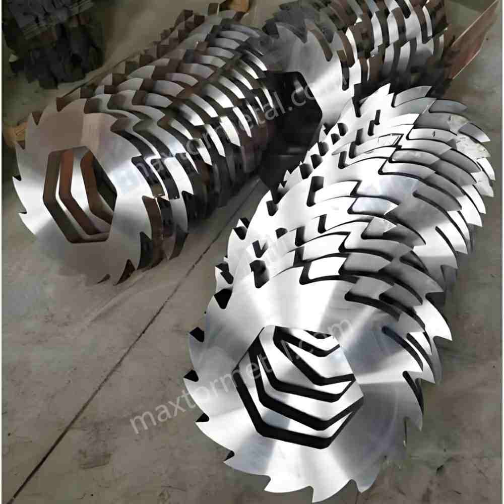
For reference on the knife category this article discusses (materials, heat treatment considerations, and failure modes), see the background on Maxtor Metal—then come back here to focus on the shredder blade stack-up and GD&T controls.
- Why multi-shaft blade tolerance stacking matters for uptime, particle size, and $/ton
- How cumulative errors create angular tilt, uneven load, vibration, and premature wear
- What this guide delivers: GD&T targets, spacer strategy, assembly/QA SOPs, and ROI
Signaux de défaillance sur le terrain
Throughput, energy, and particle-size drift
In a healthy multi-shaft stack, each cutter shares load in a repeatable way, and the interlocking gap stays stable across the working width.
When the stack starts to “walk” dimensionally, the first signal is usually subtle: throughput becomes harder to hold, kWh/ton creeps up, and output particle size spreads. Operators compensate by changing screen, feed rate, or reversing behavior—but the underlying issue is often geometric.
Why geometry shows up as energy and size drift: if certain knives contact earlier (because the stack is tilted), those edges do more work per revolution. That creates localized heating and faster edge rounding. As edges round unevenly, the shredder shifts from shearing to tearing in parts of the stack, which increases energy and worsens size control.
Vibration, noise, and current spikes at load
Vibration that increases with load (not just speed) is a classic sign of uneven contact and cyclic loading.
When stacked faces aren’t flat/parallel, the assembly effectively becomes a shallow cone. Under clamp load it may look “seated,” but under cutting load it rocks microscopically. That rocking translates into oscillating torque demand, which you see as current spikes.
If you’re doing condition monitoring: look for vibration that correlates with cutting events and a repeatable “signature” that grows after knife rotations or maintenance cycles. It often points to the stack geometry changing, not bearings failing first.
Edge quality, premature wear, and interlocking-gap instability
Three practical symptoms show up together:
- Edge quality changes: rounded edges in one axial region while another region still looks sharp.
- Premature wear patterns: polishing/fretting bands on spacer faces or knife sides, indicating micro-slip.
- Gap instability: measured interlocking clearance varies around the rotation, or varies by axial position.
If you can measure the interlocking gap at multiple angular positions and it varies, you’re usually looking at a runout/tilt problem. If it varies by axial position, you’re often looking at cumulative thickness and face-orientation variation.
Mécanisme et objectifs GD&T

How cumulative variation skews full shafts
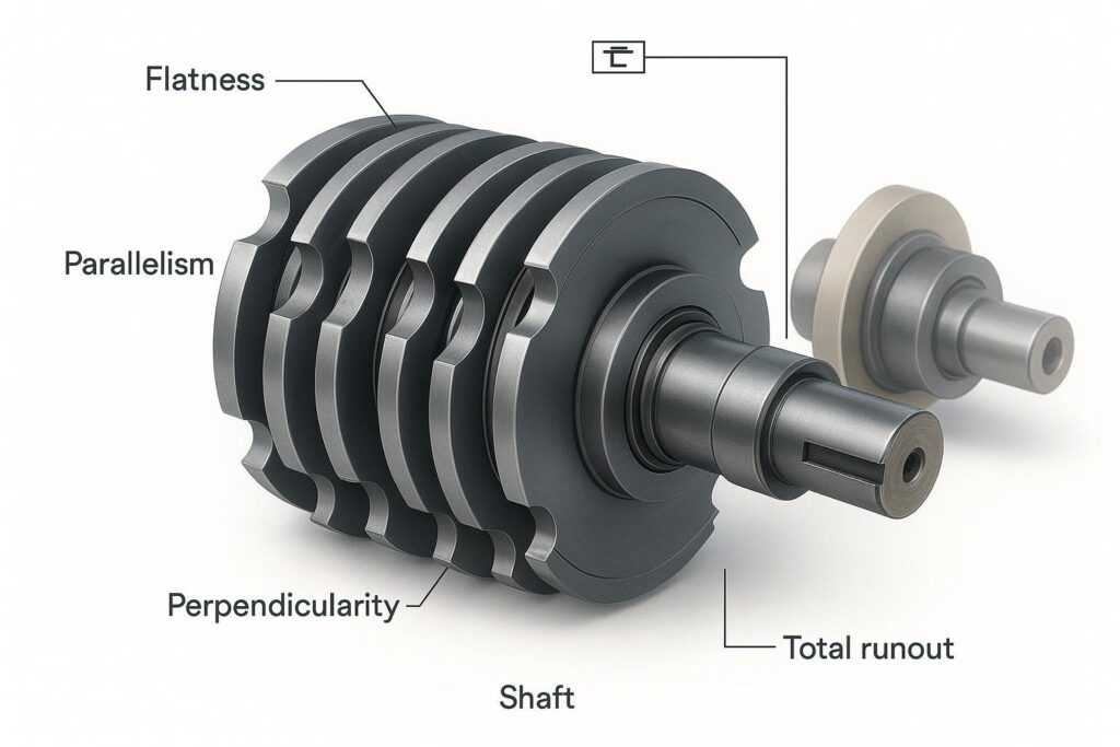
A multi-shaft stack behaves like a long “beam” of alternating blades and spacers.
Each interface introduces potential angular error:
- blade face flatness error
- spacer face flatness error
- lack of parallelism between the two faces of a blade or spacer
- lack of perpendicularity between a face and the bore/shaft datum axis
- bore positional/roundness issues (often hidden as “it fits”)
Even if each part is “within print,” the direction of those errors matters. If many parts bias the same way, you can create measurable tilt and a large end-to-end face runout.
A useful mental model: each element contributes a small wedge angle. Over 20–30 elements, those wedge angles can align and create a meaningful slope. That slope shifts where knives touch, changes the interlocking gap, and can push load into one side of the cutters and into bearings.
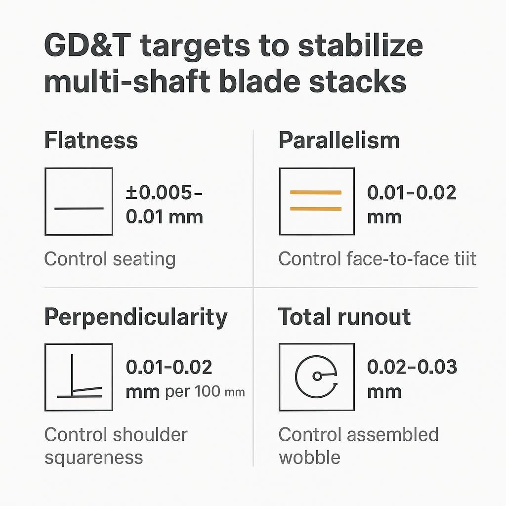
Callouts to control it: flatness, parallelism, perpendicularity, runout
GD&T is the cleanest way to express what you’re actually trying to control: seating, orientation to a datum axis, et assembled wobble.
For definitions and symbol rules, the two authoritative references are the U.S. standard ASME Y14.5 Dimensionnement et tolérancement and the ISO GPS standard ISO 1101: Geometrical tolerancing.
Voici practical starting targets many shops can hold with grinding/lapping and capable inspection. These ranges are calibrated against typical interlocking gap requirements of 1.5–3.0 mm at rotor OD of 300–400 mm across a 20–30 element stack; tighter gap targets or longer stacks require proportionally tighter controls. Treat them as engineering starting points to validate against your specific design and measurement capability.
How to apply these callouts (what to put on the drawing):
- Flatness on spacer and blade seating faces controls how repeatably each layer contacts under clamp load.
- Parallelism between opposite faces (within a spacer or blade) controls wedge angle—the hidden driver of tilt.
- Perpendicularity of seating faces to the datum axis (bore/shaft) controls face squareness to rotation.
- Total runout of critical OD/ID surfaces relative to datum axis controls the assembled “wobble” that becomes gap variation around the rotation.
If you’re building a drawing package, GD&T runout control is what turns these requirements into an inspectionable acceptance gate: you can measure it after assembly and stop bad stacks before they go into service.
Surface finish and datums for stable stacks
Once geometry is controlled, surface finish determines whether the stack stays put—or creeps.
Practical guidance:
- Seat on controlled datums. Don’t leave the datum scheme ambiguous. Choose a bore/shaft datum axis and define which face is primary seating datum.
- Avoid mixed datum logic (e.g., some features referenced to OD, others to bore) unless you have a manufacturing reason and you can verify coaxiality/runout.
- Specify surface finish on mating faces to reduce embedment and micro-slip. Rough faces “bed in” under torque and temperature cycling, changing preload and tilt.
If you’re seeing fretting: it’s often a sign of micro-motion from wedge angle + insufficient friction stability. Solve the geometry first; then tune finish and clamping.
Entretoises de précision et ajustement sélectif
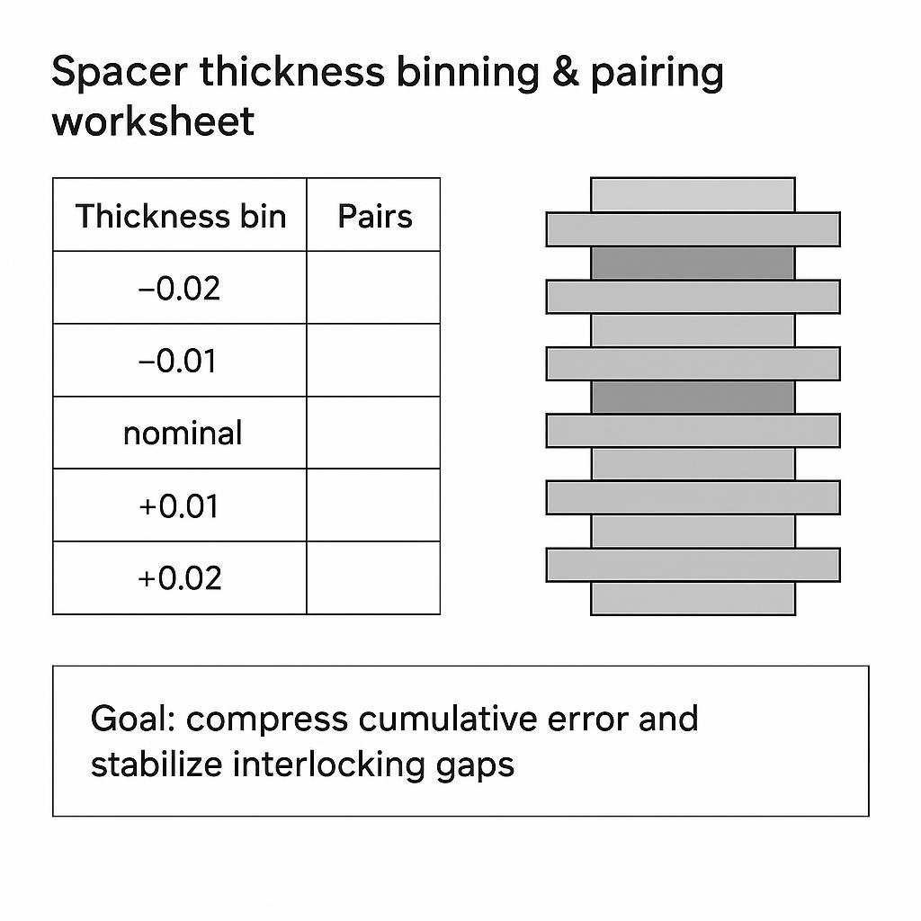
Thickness grading in 0.01–0.02 mm bands
If your stack is 20–30 elements, treating spacers as “all the same” is where the tolerance stack becomes unavoidable.
A pragmatic approach is spacer thickness grading:
- Inspect each spacer thickness with a known method (mic, bench comparator, or CMM depending on tolerance).
- Bin spacers into tight bands (0.01–0.02 mm increments).
- Build matched sets that alternate high/low thickness to cancel bias.
This doesn’t magically remove variation, but it prevents a worst-case scenario where all thick parts end up on one side of a stack and create a step change in gap.
What “good” looks like in practice:
- you can assemble multiple stacks from the same batch and see similar post-assembly TIR
- gap checks repeat after reassembly (same parts, same order)
- the stack does not “settle” into a new geometry after the first hours of operation
Matched/lapped faces and material/HT choices
Selective fit works best when faces behave predictably under clamp load.
Controls that matter:
- Matched faces: lapping or fine grinding to improve flatness and reduce embedment
- Material stability: choose spacer materials and heat treatment that resist creep at operating temperature
- Hardness balance: if spacers are much softer than knives, they become the sacrificial “settling layer,” changing preload and geometry
Where operations often get burned is inconsistent heat treat or residual stress relief, especially when spacers are thin. A thin ring that moves 0.01 mm after stress relief can erase your whole inspection effort.
In programs Maxtor Metal has supported, matched-face components were supplied with full QC packs — covering material certificates, dimensional inspection reports, and traceability records — giving procurement teams a closed traceability loop across multiple lots. The point isn’t the supplier; it’s that the documentation structure matters: without traceable QC records per lot, you can’t prove the tolerance chain held across builds.
Contrôles d'assemblage et d'assurance qualité (QA)
Torque/clamping sequence to avoid elastic tilt
Even with perfect parts, you can assemble tilt into the stack.
Common ways this happens:
- tightening one end fully before the stack is uniformly seated
- clamping over contamination (chips, burrs, oil film inconsistencies)
- tightening against a face that is not perpendicular to the datum axis
Practical controls:
- Clean and verify: wipe faces; stone burrs; verify no raised edges.
- Stage torque: bring clamp load up in increments (e.g., 30% → 60% → 100%) with a repeatable sequence.
- Rotate and re-seat: after initial torque, rotate the assembly and re-check seat contact if your design allows.
- Record torque + tool: torque wrench ID/calibration status matters if you’re chasing repeatability.
Post-assembly TIR/runout checks and acceptance limits
A decision-stage SOP needs a hard “go/no-go” gate.
Que vérifier :
- OD TIR near the cutting zone (a functional diameter that represents where the knives actually work)
- stack end-face axial runout at an accessible outer spacer/end face
- stack height / end-to-end dimension to confirm the axial build matches the intended working width
A practical, repeatable setup used in many shops:
- Fixture: a clean master shaft supported on V-blocks (or an equivalent datum-consistent setup)
- Indicator resolution: choose an indicator you can trust at the tolerance you’re trying to control (for tight stacks, a 0.001 mm dial indicator is common). For CMM-based verification of individual components before assembly, the acceptance and reverification test framework is defined in ISO 10360-2 — the same standard referenced in incoming inspection workflows.
- Measurement locations (examples):
- Point A — knife OD: measure OD TIR at the knife outside diameter, about ~5 mm from the knife face (close to the functional region)
- Point B — stack end face: measure axial runout on the outer spacer/end face
Recommended sequence (reduce clamp-induced error and catch problems early):
- Clean and verify: wipe the shaft and faces; solvent-clean; remove burrs; confirm the shaft shoulder seats cleanly.
- Build with light preload: install components and apply a light preload.
- Rotate and check early: rotate the shaft and measure OD TIR before full torque.
- Stage torque: tighten in controlled steps (e.g., 30% → 60% → 100%) with a repeatable pattern.
- Re-check after final torque: measure OD TIR and end-face runout again.
- In-process checks for long stacks: consider a rule like “check local TIR after every 5 knives” to prevent compounding an error that only shows up at the end.
Acceptance limits depend on shredder size and gap requirements, but the key is cohérence:
- pick one or two measurement points that correlate with gap stability
- measure the same way every time (same datum setup, same indicator resolution, same rotation method)
- capture the value in a traceable recordFor the incoming-inspection side of the same documentation workflow — covering CMM sampling plans, EN 10204 MTR validation, and lot dossier structure — see Aftermarket Shredder Knives Procurement: The Audit-Ready Checklist.
Suggested record fields (what makes troubleshooting possible later):
- date/time, ambient temperature (if relevant)
- stack ID, knife/spacer lot IDs, as-assembled order
- fixture/datum method (e.g., master shaft + V-block)
- indicator type and resolution, instrument ID/calibration status
- staged torque values + tool ID
- OD TIR at Point A (max/min) and end-face runout at Point B
- pass/fail decision + rework notes
If you don’t already have a measurement method, align it to your drawing standard (ASME Y14.5 or ISO 1101) so inspection and engineering are speaking the same language.
Shaft straightness, bearing alignment, and traceability data
Stack control fails if the shaft/bearing system is not straight and aligned.
Practical checks:
- Shaft straightness verification before assembly (especially after overload events)
- Bearing alignment checks during rebuilds (housing faces, bore alignment)
- Traçabilité of blade/spacer lots and assembly order
A simple improvement that pays back fast: record the as-assembled stack order (part IDs or batch IDs) alongside the runout result. When a field failure happens, you can see whether the issue repeats with a specific lot, a specific stack order, or a specific assembly team.
Mathématiques de l'empilage des tolérances utilisées par les ingénieurs
Worst-case vs. RSS for multi-shaft blade stacks
Two math models show up in tolerance work:
- Worst-case stack-up: assume every tolerance hits its worst direction at the same time. This is conservative and can force expensive tolerances, but it’s useful when failure is unacceptable.
- RSS (Root Sum Square): assumes independent variation and combines tolerances statistically. This often matches reality better when processes are stable.
For an authoritative reference that discusses worst-case vs. statistical (including RSS) tolerance analysis, see NIST’s NIST IR 6524, Information Models for Design Tolerancing (2000).
For shredder stacks, use worst-case thinking to identify what can catastrophically break gap control, and RSS thinking to set realistic process capability targets. For measurement uncertainty quantification that underpins guard band decisions, see JCGM 100:2008 (GUM) — Guide to the Expression of Uncertainty in Measurement, published by the Joint Committee for Guides in Metrology.
Building a tolerance chain for blades, spacers, and bores
A workable tolerance chain for a blade stack should include more than “thickness.” At minimum, track:
- blade thickness tolerance (size)
- spacer thickness tolerance (size)
- face parallelism within each component (orientation)
- face perpendicularity to datum axis (orientation)
- bore-to-face relationships that affect seating (orientation/runout)
One simple chain:
- Define the functional requirement: allowable gap variation and allowable runout at the cutting region.
- Convert that into measurable inspection outputs: max TIR at a chosen diameter, max face runout at a chosen face.
- Allocate tolerance budget across part features:
- keep wedge drivers (parallelism/perpendicularity) tight
- allow more tolerance where it doesn’t create wedge or wobble
- Verify with measurement capability: a tolerance you can’t measure consistently is not a control—it’s a wish.
Translating stack results into gaps, life, and $/ton
This is where the decision gets made: does tighter control pay back?
Translate geometry → KPI via three links:
- Geometry → contact pattern: tilt/runout concentrates load on a subset of edges.
- Contact pattern → wear rate: concentrated load rounds edges faster and destabilizes the interlocking gap.
- Wear rate → economics: more sharpening/replacement, more downtime events, and higher kWh/ton.
A disciplined way to show ROI without making up numbers:
- track baseline: downtime hours/month, knife change interval, kWh/ton, particle size rejects
- implement controls: GD&T callouts + spacer binning + torque/TIR gates
- re-measure over one knife-life cycle
If the runout and gap drift reduce and the knife interval extends, the payback is usually obvious—especially on high-throughput recycling lines.
Applicabilité et limites
The GD&T ranges and acceptance-gate ideas in this guide are starting targets, not universal values.
What you should validate before locking numbers on a drawing:
- OEM constraints and drawing standard: align the datum scheme and inspection method with your organization’s chosen standard (ASME Y14.5 or ISO 1101) and any OEM requirements.
- Machine size, speed, and functional clearance: higher rotor speed, narrower inter-knife clearance, and harder/abrasive feed typically require tighter controls and more frequent verification.
- Measurement capability: a tolerance you can’t measure repeatably (fixture, datum setup, indicator resolution, operator method) isn’t a real control.
- Operating variability: feed composition, moisture, and operator behavior can amplify (or mask) geometry improvements.
Use this article to build a controlled process (drawing → parts → assembly → verification). Then confirm the numeric targets with your own stack trials and inspection repeatability studies.
Étude de cas anonymisée : Audit de l'empilage sur un broyeur à quatre arbres, résultats avant/après
The following example is anonymized to protect OEM drawings and proprietary dimensions. It’s included to show how a tolerance-chain problem is usually verified, corrected, and held en production.
Application snapshot
- Machine: four-shaft industrial shredder
- Alimentation: mixed plastic + light aluminum scrap
- Rotor speed: 18–28 rpm
- Rotor OD: ~340 mm
- Knife OD: 315 mm
- Working width: 760 mm
- Shaft length (between bearings): ~930 mm
Stack configuration
Per shaft:
- 20 rotary knives
- 19 spacers
Total stacked components per shaft: 39 pieces
Approximate stack height: ~742 mm (20 × 22 mm knives + 19 × 16 mm spacers)
Critical inspection points and method
- Fixture: master shaft + V-blocks
- Indicateur: 0.001 mm dial indicator
- Point A — knife OD TIR: measure at knife OD, ~5 mm from the knife face; rotate one full revolution and record maximum TIR.
- Point B — stack end-face axial runout: measure on the outer spacer end face.
- Point C — CMM spot checks: sample 3 knives per batch to confirm bore position and key GD&T items (face flatness, parallelism, perpendicularity) against the drawing datums.
A field-proven sequence that reduced clamp-induced error:
Clean shaft → deburr spacer faces → check shaft shoulder → install knives → light preload → rotate shaft → measure OD TIR → final torque → re-check TIR.
Avant l'amélioration
From three consecutive knife-change records:
- Knife edge/OD TIR: 0.08–0.15 mm (max observed 0.17 mm)
- Stack axial runout: 0.06–0.10 mm
- Inter-knife clearance drift: design 2.00 mm; measured 1.93–2.09 mm (about ±0.08 mm)
- Knife life: ~420–520 operating hours, with uneven wear and localized chipping
- Specific energy (mixed plastics): ~24–27 kWh/t, rising as knives wore
Root-cause finding: individual parts were often “within print,” but the assembly accumulated error from spacer thickness variation, burrs, bore eccentricity, face-to-bore squareness, and shoulder contamination—creating stack wobble.
Improvements implemented
- Drawing control: revised datum scheme (bore as Datum A; reference face as Datum B) and added geometric controls such as total runout, flatness, and perpendicularity (not thickness only).
- Selective fit: binned knives and spacers in 0.005 mm thickness bands and built matched sets.
- Assembly discipline: changed from one-time tightening to staged torque (30% → 60% → 100%) with a repeatable pattern.
- Cleanliness/burr control: added stone deburring, solvent cleaning, and compressed-air inspection; any visible burrs were corrected immediately.
- Acceptance gates (internal):
- knife OD TIR ≤ 0.05 mm
- stack end-face runout ≤ 0.04 mm
- stack height ± 0.05 mm
Note: these are internal quality gates set tighter than the minimum “it can still run” condition.
Après amélioration
Across three consecutive batches:
- Knife OD TIR: 0.02–0.04 mm
- Stack end-face runout: 0.015–0.030 mm
- Inter-knife clearance: 2.00 ± 0.03 mm
- Knife life: 610–720 operating hours (about +30–40%)
- Specific energy: 21–23 kWh/t (about −8–12%), with a more stable trend
A practical observation worth capturing in your SOP: experienced operators often rotate the shaft and re-check more frequently during assembly. In this example, adding a rule like “check local TIR after every 5 knives” reduced rework and improved repeatability for newer operators.
Caveat: the magnitude of improvement depends on feed composition, moisture, and feeding behavior. In this case, feed was mixed plastic and light aluminum scrap at 18–28 rpm — results were consistent across three consecutive batches under these conditions. The value of the process is that it makes the stack geometry measurable and controllable: once geometry is controlled, performance variation can be attributed to feed and process inputs, not to hidden assembly error.
Conclusion
- Key checks: GD&T targets, spacer grading, torque/TIR verification
- Expected KPI gains: steadier throughput, energy/ton down, longer blade life, fewer stops
If you want a practical way to start, treat this as a three-part control loop:
- Specify geometry that actually controls the failure modes (flatness/parallelism/perpendicularity/runout), using your chosen drawing standard (ASME Y14.5 or ISO 1101).
- Control the stack statistically with spacer grading and matched sets so the tolerance chain doesn’t drift lot-to-lot.
- Verify the assembled reality with a repeatable post-assembly TIR/runout check and traceable records.
A compatible receiving dossier structure for the procurement side of this workflow is covered in the audit-ready procurement guide.
That’s the technical conclusion engineers can defend: if you control wedge angle drivers and verify TIR after assembly, you remove the hidden mechanism that turns “within print” parts into an unstable stack.
To put the three-step control loop into practice, the following starter reference covers the key items:
Stack-up review checklist (drawing + incoming inspection)
- Drawing has explicit GD&T callouts for flatness, parallelism, perpendicularity, and total runout — not thickness only
- Datum scheme is defined (bore/shaft as Datum A; reference seating face as Datum B) and consistent across drawing and CMM program
- Spacer and blade thickness tolerance is specified; binning band (e.g. 0.005 mm) is noted on the inspection plan
- Incoming inspection verifies face flatness and parallelism in addition to thickness
QC pack structure (per lot)
- Material certificate (EN 10204 type, heat/lot number, grade, chemical/mechanical properties)
- Dimensional inspection report (CTF features: thickness, flatness, parallelism, perpendicularity, bore position)
- Traceability fields: lot ID, assembly order, knife/spacer batch IDs
Runout/TIR record fields (per assembled stack)
- Stack ID, assembly date, ambient temperature
- Knife/spacer lot IDs and as-assembled order
- Fixture method (master shaft + V-block or equivalent), indicator type/resolution/cal status
- Staged torque values (30% / 60% / 100%) + torque tool ID
- OD TIR at Point A (max/min), end-face runout at Point B
- Pass/fail decision + rework notes if applicable
If you’re reviewing knife programs or qualifying aftermarket parts, the product context page for Maxtor Metal is a useful reference point for materials and failure modes—but the reliability win comes from drawing controls and inspection discipline.
Jesse Xu est un Senior Quality Engineer à Maxtor Metal avec 15 years of experience in industrial blade quality assurance and failure analysis. His work focuses on turning field symptoms (uneven wear, chipping, vibration, gap drift) into measurable root causes—such as tolerance stack-up, datum-control issues, and process variation.
Credentials and qualifications:
- ASQ — Certified Quality Engineer (CQE)
- ISO 9001 Lead Auditor
- ASNT Level II
About Maxtor Metal: Maxtor Metal manufactures custom, precision-ground industrial blades and supporting components (including matched-face knives and spacers) and can provide import-ready documentation packages such as material certificates, dimensional inspection reports, and traceability records for OEM and aftermarket programs.
FAQ
Q: Qu'est-ce qui provoque des vibrations dans un broyeur bi-arbre ou multi-arbres après un changement de couteaux ?
R: De légères erreurs d'angle de coin (parallélisme/perpendicularité des faces) et la variation d'épaisseur accumulée peuvent se traduire par de l'inclinaison et du faux-rond lors de l'assemblage. Sous charge, cela se manifeste par une demande de couple cyclique et des pics de vibration/courant. Un contrôle du faux-rond (TIR) après assemblage est le moyen le plus rapide de le confirmer.
Q: Comment calculer l'empilage des tolérances pour un train de couteaux de broyeur ?
R: Commencez par une exigence fonctionnelle (dérive de jeu ou TIR admissible), puis établissez une chaîne comprenant les tolérances d'épaisseur et les tolérances d'orientation qui créent un effet de coin (parallélisme/perpendicularité). Utilisez la méthode du pire des cas (worst-case) pour identifier las combinaisons catastrophiques, et la méthode RSS lorsque la variation de votre processus est stable.
Q: Quels contrôles GD&T sont les plus importants pour les couteaux et entretoises empilés ?
R: La planéité des faces d'appui, le parallélisme entre les faces opposées, la perpendicularité des faces d'appui par rapport à l'axe de référence et le faux-rond total par rapport à l'axe de référence sont les éléments les plus directement liés aux modes de défaillance par inclinaison/faux-rond.
Q: Quel est le faux-rond/TIR admissible pour un train de couteaux de broyeur multi-arbres ?
R: Cela dépend de la taille du broyeur, de sa vitesse et de la stabilité requise du jeu d'engrenage (interlocking gap). L'approche pratique consiste à choisir un point de mesure corrélé à la variation du jeu, à définir une limite d'acceptation basée sur vos exigences de jeu et votre capacité d'inspection, puis à suivre son évolution dans le temps pour détecter toute dérive.
Q: Comment le calibrage de l'épaisseur des entretoises réduit-il l'instabilité du jeu ?
R: Le tri des entretoises en plages d'épaisseur étroites (binning) et la constitution de jeux appariés empêchent l'accumulation des écarts dans une seule direction. Cela n'éliminera pas la variation, mais cela comprime l'erreur cumulative et améliore la répétabilité d'un assemblage à l'autre.
Q: Pourquoi des couteaux « dans la tolérance » s'usent-ils quand même de manière irrégulière sur le train ?
R: Parce que le fait d'être « dans la tolérance » ne garantit pas que la direction des erreurs s'annule. Si plusieurs pièces ont des faces légèrement non parallèles dans la même direction, le train s'incline et concentre la charge sur certains couteaux.
Q: Dois-je utiliser ASME Y14.5 ou ISO 1101 pour les plans de couteaux de broyeur ?
R: Utilisez la norme prise en charge par votre organisation et vos ressources d'inspection. Dans les programmes centrés sur les États-Unis, l'ASME Y14.5 est courante ; dans les programmes internationaux, l'ISO 1101 au sein du système ISO GPS est courante. Le plus grand risque est de mélanger les règles ou de laisser la logique des références (datums) ambiguë.
Q: Comment documenter l'assemblage du train de couteaux de broyeur pour la traçabilité ?
R: Enregistrez les identifiants de pièce/lot pour les couteaux et les entretoises, l'ordre d'assemblage, la méthode de couple/l'ID de l'outil, ainsi que los résultats de mesure du faux-rond/TIR après assemblage. Cela vous permet d'obtenir une boucle fermée (closed loop) lors de l'analyse des défaillances sur site.