


A slitting line can have excellent knife steel and still struggle with burrs, width drift, and premature chipping if the bore–arbor interface is poorly specified or inconsistently verified. This checklist is meant to be used as an engineering audit: you take an OEM slitter knife blueprint, compare it against the spindle/arbor reality, and log pass/fail gates before the tooling ever touches coil.
If your line uses roller shearing blades in addition to circular slitters, keep the product geometry and inspection expectations aligned across tooling families. Dimensional tolerances, axial runout limits, and bore fit requirements vary significantly by material grade and line speed—for a full engineering overview, see Maxtor Metal’s guide to rotary slitter knives and roller shear blades, which covers material selection, clearance engineering, and the tolerance divide between ±0.01 mm and ±0.002 mm that directly affects spindle fit decisions.
Maxtor Metal teams often see the same pattern during audit reviews: edge-quality issues get blamed on “knife quality,” while the real root cause lives upstream in fit selection, runout control, and seating surface condition.
- Purpose: define an engineering audit for OEM slitter knife blueprint on spindle fit
- Scope: ISO fits, runout/parallelism, surface finish, and fit-check workflow
- Outcomes: stable edge quality, lower burrs, longer life, predictable uptime
Ajustements et tolérances ISO
Hole-basis fits for arbor–bore (H7/g6, H7/h6, H7/f6)
Most slitter stacks are easiest to control using a hole-basis system: the knife/spacer bore is specified as “H7,” and the arbor seating diameter is specified as a shaft tolerance zone (g6, h6, f6) to tune clearance.
- H7/g6: a controlled sliding/locational clearance fit when you need repeatable assembly with minimal “float,” but still expect disassembly during changeovers.
- H7/h6: the “neutral” shaft position (h) tends to push the clearance toward the smaller end; used when you want very consistent location but still a practical assembly.
- H7/f6: a bit more clearance than g6/h6; used when thermal expansion, contamination risk, or frequent stack changes make tight fits unreliable.
If your drawing package is ISO-based, the baseline references are the ISO Store pages for ISO 286-1 et ISO 286-2 (fits and limit deviations).
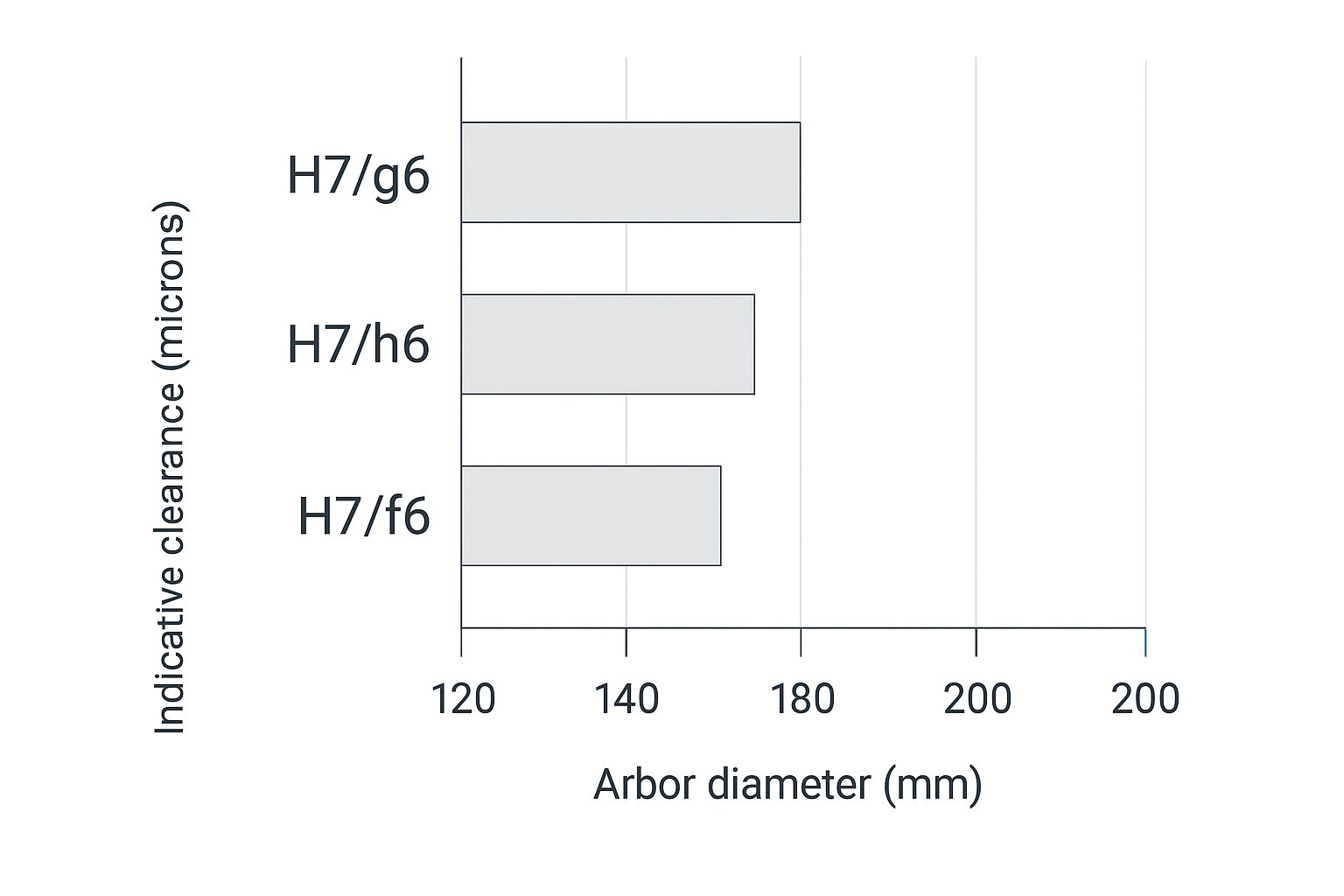
Indicative clearance bands for 120–200 mm nominal sizes
For common slitter bores in the 120–200 mm range, the clearance you actually get from H7/g6 vs H7/h6 vs H7/f6 can be small in absolute terms, but large in process impact. Two practical notes:
Worked example: ISO 286 limits for a 150 mm bore (how to pull the numbers)
Below is a method demonstration for extracting limits from ISO 286 tables. Always use your organization’s official copy of ISO 286 (or internal standards library) as the controlling source.
How to cite ISO tables in an audit record (so anyone can reproduce the numbers)
When you pull limits from ISO 286 tables, record where the values came from, not just the final min/max.
Include these fields in your audit record (or in the Notes column of the CSV):
- ISO document used (example: ISO 286-2)
- Diameter step used for the nominal size (the range bucket that contains the nominal diameter)
- IT grade used (IT6 / IT7, etc.)
- Fundamental deviation letter used (H for hole; g/h/f for shaft)
- Table/Figure reference from your organization’s controlled copy (table number or figure ID as labeled in your standards library)
- Rounding rule (if your internal practice specifies rounding for reporting)
This makes the clearance band fully traceable even when different plants use different standards portals or editions. The blueprint remains controlling; the audit record simply documents which ISO table entry was used to interpret the fit callout.
Example input
- Diamètre nominal de l'alésage : 150 mm
- Tolérance de l'alésage : H7 (alésage de base)
- Zones d'arbre candidates : g6, h6, f6
Étape par étape
- Dans la norme ISO 286-2, localisez l'intervalle de diamètre qui contient 150 mm.
- Lisez la IT7 valeur de tolérance pour cet intervalle de diamètre.
- Pour la position de l'alésage H, l'écart inférieur EI = 0. Par conséquent :
- Limite inférieure de l'alésage = 150.000 mm
- Limite supérieure de l'alésage = 150.000 mm + IT7
- Pour la tolérance de l'arbre (g6 / h6 / f6) :
- Lisez la écart fondamental pour la lettre (g / h / f) au même intervalle de diamètre.
- Lisez IT6 pour cet intervalle de diamètre.
- Limites de l'arbre = (150.000 mm + écart) à (150.000 mm + écart + IT6)
- Jeu = (limite de l'alésage) − (limite de l'arbre). Enregistrez le jeu minimal et le jeu maximal.
Ce qu'il faut enregistrer sur la fiche d'audit
Un exemple numérique (à titre illustratif uniquement) : 150 mm H7/g6
Ci-dessous se trouve une seule ligne de calcul utilisant des valeurs illustratives (exemple uniquement). Vérifiez toujours par rapport aux tableaux ISO 286 contrôlés de votre usine et aux notes de plan.
Hypothèse (illustrative) :
- Alésage : 150 H7 → EI = 0,000 mm, ES = +0,040 mm
- Arbre : 150 g6 → ei = -0,025 mm, es = -0,015 mm
Alors:
- Limites de l'alésage : 000 à 150.040 mm
- Limites de l'arbre : 975 à 149.985 mm
- Plage de jeu : min = 150,000 − 149,985 = 0,015 mm, max = 150,040 − 149,975 = 0,065 mm
Le but de l'inclusion d'une ligne numérique n'est pas de remplacer la norme ISO 286 ; il est de rendre la fiche d'audit exploitable et de montrer comment calculer le jeu min/max à partir des limites extraites de vos tableaux contrôlés.
- Diamètre nominal + indication d'ajustement (ex. 150 mm H7/g6)
- Limites de l'alésage (min/max)
- Limites de l'arbre (min/max)
- Plage de jeu calculée (min/max)
Cet exemple est volontairement présenté comme une méthode de recherche des valeurs, car les valeurs correctes dépendent des tableaux d'intervalles de diamètres ISO 286 utilisés par votre usine et du diamètre nominal indiqué sur le plan.
- Le jeu n'est pas la même chose que le faux-rond. Un ajustement avec jeu “ correct ” permet toujours un faux-rond si l'alésage n'est pas coaxial au diamètre extérieur ou si les faces d'appui ne sont pas planes/propres.
- Vous avez besoin d'une plage contrôlée, pas d'une valeur unique. Les empilages réels sont soumis aux variations de température, de propreté, d'usure des entretoises et d'habitudes de montage.
Utilisez l'infographie ci-dessous pour une visualisation rapide, puis récupérez les limites réelles dans les tableaux ISO pour votre diamètre nominal.
Objectifs de rugosité de surface pour les faces d'appui (Ra, Rz)
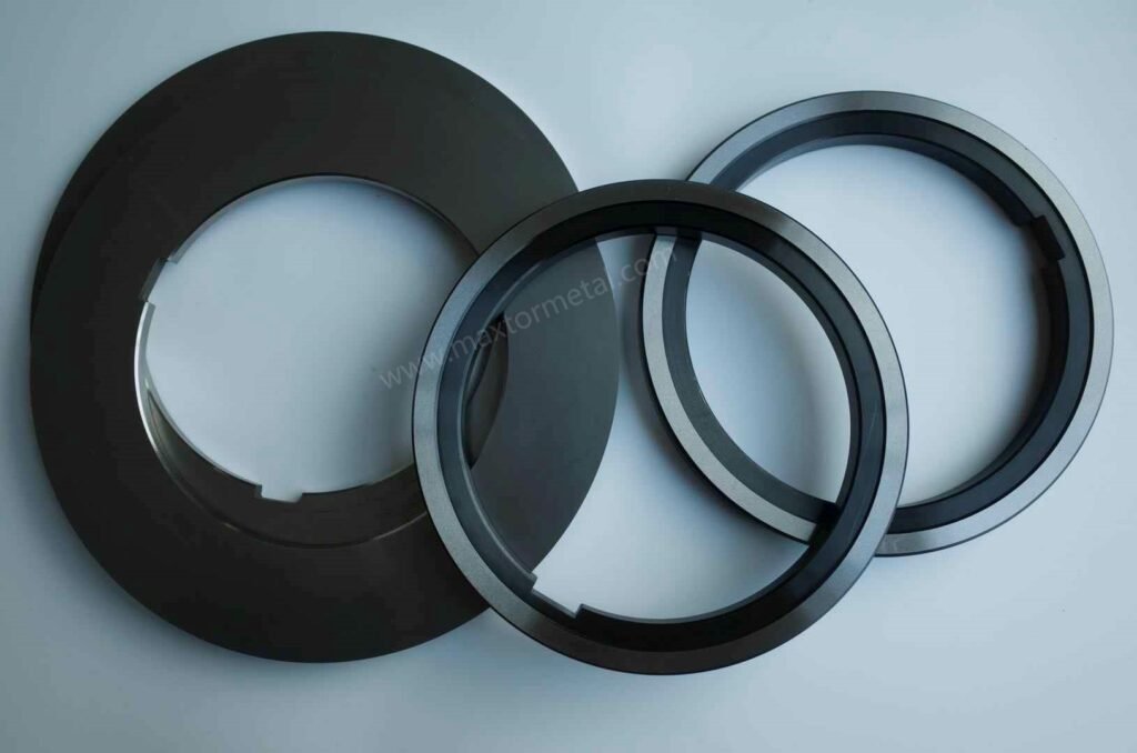
Les plans spécifient souvent l'alésage mais sous-spécifient les surfaces qui supportent réellement le positionnement axial de l'empilage : faces des moyeux de couteaux, faces des entretoises et épaulements d'arbres. En pratique, l'état de surface des faces détermine si l'empilage se “ stabilise ” de la même manière à chaque montage.
Une bonne pratique d'audit consiste à définir les exigences d'état de surface en utilisant les conventions de dessin de la norme ISO 1302 et les définitions modernes des paramètres de profil de la série ISO 21920.
Comme point de départ pour de nombreux empilages de refendage de l'acier (respectez toujours le plan lorsqu'il est spécifié) :
- Faces d'appui (faces des moyeux de couteaux, entretoises, épaulements d'arbres) : finition rectifiée fine ; une référence couramment utilisée est Ra ≤ 0,8 μm (souvent associée à Rz ≤ 3,2 μm).
- Surfaces sans fonction d'appui : une référence plus large est Ra ≤ 1,6 μm, à condition que cela ne crée pas de bavures, de dommages en relief ou de débris piégés qui affecteraient l'appui.
Note: Considérez ces valeurs comme des plages de départ typiques, et non comme des exigences universelles. Le plan du constructeur (OEM) et vos normes/plans de contrôle internes restent prioritaires.
Points clés à retenir: Si le plan contrôle la taille de l'alésage mais ignore les faces d'appui, vous pouvez “ réussir l'inspection ” tout en ayant une mauvaise qualité de coupe.
Objectifs d'acceptation d'interface de broche
Jeu radial/axial et limites de battement total (TIR) (arête de coupe, face du moyeu)
C'est là que les audits échouent souvent : les équipes tentent d'utiliser une valeur universelle unique. En réalité, vos objectifs de réception doivent être définis par :
- les indications du plan du constructeur (OEM) (première priorité)
- la chaîne de tolérance du produit (tolérance de largeur de bande, limite de bavure, spécification client)
- la vitesse de ligne et la stabilité dynamique
Cela dit, un audit nécessite tout de même des critères de validation. Utilisez deux catégories de réception simples et enregistrez-les à chaque montage :
- Battement total (TIR) de l'arête du couteau assemblé (radial) : mesuré au diamètre extérieur de coupe à l'aide d'un comparateur à cadran tout en faisant tourner l'arbre.
- Faux-rond de la face du moyeu assemblé (axial/face) : mesuré sur la face du moyeu (ou sur une face de référence contrôlée) pour détecter le voile.
Si le plan utilise les symboles ISO GPS, interprétez le faux-rond/parallélisme selon la norme ISO 1101. Si vos plans internes sont basés sur les normes ASME, alignez ces indications sur le jeu de normes GD&T choisi par votre entreprise.
Références ISO GPS / état de surface : citez votre copie interne contrôlée
Si vous utilisez des symboles ISO GPS ou des indications d'état de surface lors des audits, enregistrez la référence de la norme + définition du symbole que l'atelier utilise.
- Pour interprétation du faux-rond/parallélisme/planéité (ISO 1101), record the standard edition in your controlled library and the relevant symbol definition reference (clause/figure ID as labeled internally).
- Pour surface texture (ISO 1302 / ISO 21920 series), record the parameter set used (Ra/Rz or profile parameters) and the reference figure/table ID used by your controlled copy.
This avoids “same symbol, different interpretation” problems when multiple sites or suppliers are involved.
Practical notes for technicians:
- Use the same indicator contact point and preload each time.
- Log max/min readings and calculate TIR; don’t rely on “looks OK.”
- If you can’t repeat a reading, your setup is unstable—fix the setup before judging the part.
A practical way to set TIR / face runout acceptance targets
Material sensitivity: how coil grade affects runout tolerance
Not all materials “forgive” the same amount of assembled error. When the drawing does not specify assembled runout limits, use material sensitivity as a practical tie-breaker for choosing your acceptance tier.
If your audit process also ties fit choice and edge-quality expectations to incoming coil material requirements, ASTM’s overview of metals standards (including steel and stainless steel) can help you keep material spec language consistent across purchasing, QA, and production documentation.
- acier inoxydable 304: higher work hardening and tougher shear behavior typically makes edge quality more sensitive to wobble and radial eccentricity. Treat it as a reason to target Tier A whenever the line is capable.
- Cold-rolled carbon steel (CR): often sits in the middle—many lines can run it successfully at Tier A or Tier B depending on width tolerance and burr limits.
- Galvanized steel (GI): the zinc layer can make surface defects and edge roll more visible; if cosmetic edge expectations are tight, bias toward tighter face runout control (Tier A/B) even when radial TIR looks acceptable.
Practical rule: when switching from CR to 304 or high-cosmetic GI, tighten the first-pass audit gate (Tier A where possible), then confirm with a short trial slit before committing to full production.
Use the OEM drawing callouts as the first priority. When the drawing does not specify assembled limits, set tiered targets based on process sensitivity (material, line speed, knife diameter) and then validate with trial slits.
Recommended assumptions for the example targets below (adjust to your reality):
- Machine: high-precision coil slitting line (FIMI-compatible spindle system)
- Knife diameter: Ø180–350 mm
- Material: cold-rolled steel, galvanized steel, or stainless steel
- Material thickness: 0.4–2.0 mm (typical mid-gauge)
- Line speed: 100–300 m/min
- Inspection method: dial indicator (or CMM) with knives mounted on a qualified master arbor
- Measurement state: clean mating surfaces, specified clamping torque applied, room temperature before production
Example acceptance tiers (for audit planning and internal alignment):
| Tier | Typical application conditions | Knife edge TIR (radial) | Hub face runout (axial) |
|---|---|---|---|
| A — High precision | Precision metal slitting (CR/SS), tighter edge-quality requirements | 0.005–0.010 mm | 0.003–0.008 mm |
| B — General industrial | General metal coil slitting / medium-speed service center lines | 0.010–0.020 mm | 0.008–0.015 mm |
| C — Robust / heavy gauge | Heavy-gauge or lower-precision applications | 0.020–0.050 mm | 0.015–0.030 mm |
Audit note: These are typical internal targets under the assumptions listed above. If your OEM drawing specifies limits, the drawing wins. If you cannot repeat readings, stabilize the setup before judging the tooling.
Parallelism/flatness for spacers and overarms
Spacer and overarm geometry is the silent multiplier. A stack can have acceptable knife runout at rest, then drift under load if:
- spacer faces are not parallel
- overarm or clamp faces introduce a tilt
- the stack is clamped unevenly due to burrs or contamination
Blueprint acceptance targets should include:
- spacer face parallelism/flatness (with a defined datum scheme)
- overarm and clamp face parallelism relative to the spindle axis
Audit tip: treat spacers as precision components, not consumables. For the full specification framework—covering spacer thickness tolerance, face parallelism targets, rubber ring compression windows, and a rebuild verification template—see Entretoises de refendage de précision et anneaux en caoutchouc : Rigidité de l'empilage, contrôle du jeu et du TIR.
Cleanliness, magnetism, and thermal control thresholds
A fit system only works if the interface behaves like the drawing assumed it would.
Minimum audit thresholds to define (and enforce):
- Propreté: no trapped fines, no raised nicks, no oil film on locating faces.
- Magnetism: if parts retain swarf, you’ll get false seating and shifting; define how magnetism is checked and what you do when it’s high.
- Thermal control: define when you measure (cold vs stabilized) and how long parts must equilibrate before acceptance readings are valid.
Inspection de réception des couteaux et entretoises

Instruments and calibration traceability
Receiving inspection is only defensible if your measurements are traceable.
Checklist:
For teams that want a neutral, third-party anchor on traceability and dimensional measurement practice, NIST’s overview of dimensional metrology is a helpful reference point for how measurement results are tied back to SI and calibration discipline.
- Instruments match tolerance level (micrometers/bore gauges/indicators as appropriate)
- Calibration is current and traceable to your internal system (or an accredited lab)
- Measurement method is documented (where to touch, how many points, acceptance formula)
Bore/thickness/OD checks and blue-check acceptance
Incoming checks should separate size depuis geometry:
- Bore size: verify against the ISO fit class called out on the blueprint.
- Épaisseur: verify single-part thickness et understand how thickness stacks with spacers.
- OD: verify OD where it matters (cutting diameter, overlap behavior).
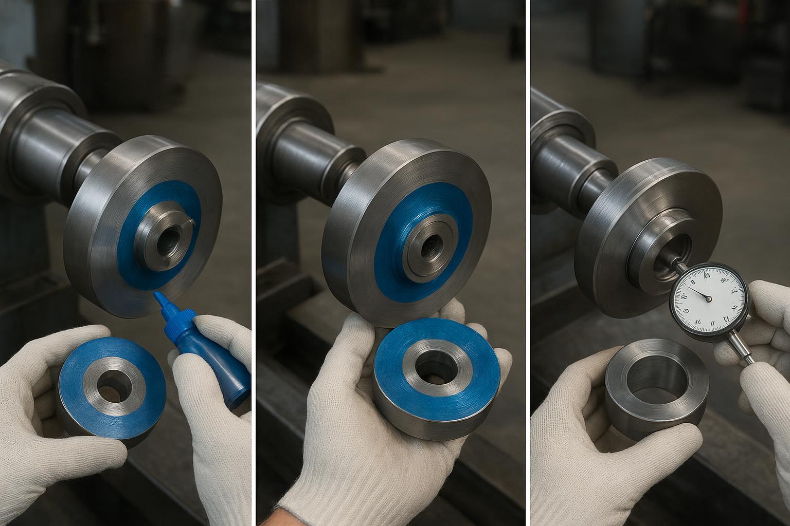
Blue-check (contact pattern) acceptance:
- establish what “good coverage” means on the seating zones
- reject parts with patchy contact indicating taper, localized high spots, or face damage
Once incoming geometry is confirmed, teams evaluating whether PM-HSS justifies its price premium over conventional tool steel can use the PM-HSS vs Tool Steel Rotary Slitter Knife ROI framework to model cost-per-ton against their actual edge life and changeover data.
Spacer width, parallelism, and face finish verification
Spacer issues show up as width drift long before they show up as a “bad knife.” Receiving inspection should include:
- width measurement with an agreed method (multiple points, temperature noted)
- parallelism/flatness verification for faces that locate the stack
- surface finish verification where the drawing calls it out
Cartographie des conditions de l'arbre
OD survey vs. specified fit band (g6/h6/f6)
Audits often stop at knife inspection. Don’t. The arbor is the datum that everything else references.
Map the arbor seating diameter:
- measure OD in multiple axial zones (seating zone vs non-seating)
- measure at multiple angular positions to detect ovality
- compare results to the specified shaft tolerance zone (g6/h6/f6)
The point isn’t to “get a number.” The point is to prove the arbor is still within the fit system your blueprint expects.
Journal and seating-zone TIR and finish
Two separate checks matter:
- Journal/seating-zone TIR relative to the spindle axis
- État de surface: damage, fretting marks, transfer material, corrosion pits
If the seating zone has raised damage, you can’t compensate it with a tighter bore tolerance.
Remedial criteria for taper/ovality and surface damage
Define repair thresholds in your audit sheet:
- taper beyond your internal limit (based on the allowed fit band)
- ovality that causes inconsistent blue-check patterns
- surface damage that creates localized high points or galling risk
Common remedies:
- controlled polish/regrind of seating zones (with documented material removal)
- replacement of worn sleeves (if applicable)
- escalation to spindle/bearing inspection when TIR is unstable
Procédure de vérification d'ajustement et de marquage bleu
Stack build order and cleanliness discipline
Fit-check is a process, not a moment.
Checklist discipline:
- Clean all locating faces before each assembly step
- Build stack in the documented order (spacers/knives/overarm components)
- Use consistent torque and clamp sequence
- Avoid “tapping to fit” unless your procedure explicitly allows it and records it
Dial-indicator sweep and acceptance logging
Minimum logging fields to make the audit useful:
- arbor ID, knife set ID, spacer set ID
- temperature condition
- knife edge TIR (radial)
- hub face runout (axial)
- notes on blue-check coverage
Make the pass/fail gate explicit. If you can’t explain why a stack was accepted, it isn’t audit-ready.
Trial slit confirmation and acceptance criteria
Even a perfect static fit can fail under load. A short trial slit should confirm:
- burr level is within baseline
- width holds within tolerance after stabilization
- no abnormal noise/vibration that suggests seating shift
Dépannage et actions correctives
Burr, tearing, rollover: gap/runout alignment nexus
When burrs spike or tearing appears:
- treat it as a système issue: knife condition + overlap/side clearance + assembled runout
- verify whether the edge TIR or face runout changed compared to the last “good” build
- check for contamination trapped between spacers/knife faces that shifts the stack under load
For a structured root-cause matrix covering all primary burr drivers—clearance/overlap, knife condition, alignment, lubrication, and tension—alongside setup windows by material family, see the Manuel de réduction des bavures de refendage.
Corrective action hierarchy:
- Clean and rebuild with controlled torque
- Replace the suspect spacer(s) with known-good references
- Re-map arbor seating zone and blue-check for contact loss
Width drift and thermal growth: spacer and bearing cues
If width drifts over a run:
- confirm spacer widths at temperature (not just at ambient)
- check whether bearing temperature rise correlates with drift (thermal growth + preload change)
- verify overarm/clamp faces are not introducing a tilt as the system warms
Correctives:
- tighten thermal control rules in the audit (stabilization time, measurement timing)
- isolate spacer wear from bearing/spindle issues by repeating runout measurements after heat soak
Fretting/galling at bore–arbor: finish and fit remediation
Fretting and galling are usually telling you one of three things:
- clearance is wrong for the actual thermal/contamination environment
- surfaces are too rough (or damaged) for repeatable sliding assembly
- clamp load and micro-movement are causing contact fatigue
Correctives:
- re-evaluate fit choice (e.g., moving from a near-line-to-line fit toward a controlled clearance when changeovers are frequent)
- repair seating surfaces and restore specified finish
- adjust cleaning/magnetism control so abrasive fines don’t become lapping compound
In slitter audit programs supported by Maxtor Metal, shops often improve audit repeatability by combining incoming measurement records with regrind history (what was removed, where contact changed, how runout shifted). That kind of data-backed loop is most useful when it stays factual—measurement methods, timestamps, and acceptance gates—rather than subjective “looks good” notes.
Conclusion
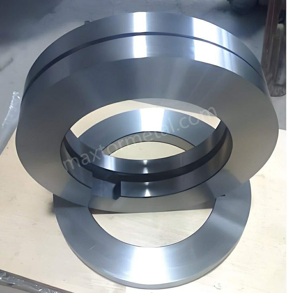
The 5 acceptance numbers to retain every build
Record these on every changeover so your audit stays traceable:
- Bore–arbor fit class used (example: H7/g6) and the nominal diameter
- Knife edge TIR (radial) at the cutting OD (max–min)
- Hub face runout (axial/face) on the reference face (max–min)
- Blue-check coverage result (pass/fail + notes)
- Trial-slit confirmation (burr baseline + width stability after warm-up)
3 common failure modes and the fastest checks
- Burr/tearing spikes → re-check edge TIR + face runout against the last “good” build, then inspect spacer/knife faces for trapped fines.
- Width drift over a run → verify spacer widths at temperature and look for overarm/clamp-induced tilt as bearings warm.
- Fretting/galling at the bore–arbor interface → review fit choice vs thermal/contamination reality, then restore seating-zone finish and cleanliness discipline.
Next steps
Standardize your documentation so every changeover produces the same minimum evidence pack: fit class used, runout readings, blue-check coverage, and trial-slit confirmation. That’s the fastest way to keep edge quality stable across teams and shifts.
If your audit results indicate a knife material or coating change is warranted, the guide de ROI des couteaux de refendage rotatifs provides a cost-per-ton model and case-style data for AHSS, stainless, and aluminum slitting.
If you also maintain roller shearing tooling in the same plant, it helps to keep product documentation aligned so inspection and regrind records don’t fragment across tool types. A low-friction internal reference point is the Maxtor Metal roller shearing blades.
Auteur: Jerry Chu, Technical Support Specialist (After-sales Service), Maxtor Metal
Jerry has 10 years of cross-industry field experience supporting cutting and slitting applications (paper, plastics recycling, metal coil slitting, wood processing), with a practical focus on reducing burrs, controlling dust, and stabilizing on-line cutting quality.
Certifications: PMP, CMRP
Dernière mise à jour : 2026-06-16
Revue technique et contrôle de documents
To improve audit repeatability across teams and shifts, treat this checklist as a controlled technical document.
- Intended use: engineering/QA checklist for slitter knife bore–arbor fit and assembled runout verification.
- Standards baseline: ISO 286 (fits), ISO 1101 (GPS/GD&T), ISO 1302 and ISO 21920 (surface texture). If your drawings use ASME GD&T, align symbols and datum logic to your internal standard set.
- Review approach: update the checklist when your OEM drawings change, when spindle/arbor regrinds occur, or when you find repeated nonconformities in runout/blue-check patterns.
- Evidence pack: keep runout logs, temperature condition, clamping torque, and blue-check notes together with the knife/spacer/arbor IDs.
Downloadable audit template (recommended fields)
If you maintain a controlled form, include at minimum:
- Line/asset ID, arbor ID, knife set ID, spacer set ID
- Nominal bore size + fit callout used
- Measurement temperature condition and stabilization time
- Knife edge TIR (radial), hub face runout (axial)
- Blue-check coverage pass/fail + notes
- Trial-slit confirmation (burr baseline, width stability)
- Corrective action taken and re-check results
Tip: Assign a document number and revision date to your template so the shop always uses the latest version.
Copy-paste Excel header (CSV)
Paste the single header row below into Excel (or any CMMS/QMS form builder) and use it as your standard “evidence pack” structure.
Document No.,Revision,Last Updated,Plant/Site,Line/Asset ID,Machine/OEM,Spindle System,Shift,Date,Inspector,Ambient Temp (°C),Stabilization Time (min),Arbor ID,Arbor Nominal OD (mm),Arbor Fit Zone (e.g., g6/h6/f6),Arbor OD Zone A (mm),Arbor OD Zone B (mm),Arbor OD Zone C (mm),Arbor Ovality Max (mm),Arbor Taper (mm),Arbor Seating Zone TIR (mm),Arbor Surface Condition (Pass/Fail),Knife Set ID,Spacer Set ID,Nominal Bore (mm),Blueprint Fit Callout (e.g., H7/g6),ISO 286 Reference (Doc + Edition),ISO 286 Diameter Step,ISO 286 IT Grade (e.g., IT6/IT7),ISO 286 Fundamental Deviation Letters (e.g., H/g),ISO 286 Table/Figure ID (Internal),ISO 286 Rounding Rule, Hole Limit Min (mm),Hole Limit Max (mm),Shaft Limit Min (mm),Shaft Limit Max (mm),Clearance Min (mm),Clearance Max (mm),ISO 1101 Reference (Internal Clause/Figure ID),ISO 1302 Reference (Internal Figure/Table ID),ISO 21920 Reference (Internal Figure/Table ID),Surface Texture Parameter Set (e.g., Ra/Rz),Assembly Torque/Clamp Spec,Contact Cleanliness (Pass/Fail),Magnetism Check (Pass/Fail),Blue-check Coverage (Pass/Fail),Blue-check Notes,Knife Diameter (mm),Material,Material Thickness (mm),Line Speed Setpoint (m/min),Acceptance Tier (A/B/C),Knife Edge TIR (Radial) (mm),Hub Face Runout (Axial) (mm),Measurement Method (Indicator/CMM),Indicator Resolution (mm),Setup Repeatability Check (Pass/Fail),Trial Slit Done (Y/N),Burr Result (Pass/Fail),Width Stability Result (Pass/Fail),Noise/Vibration Observed (Y/N),Corrective Action Taken,Re-check Knife Edge TIR (mm),Re-check Hub Face Runout (mm),Final Disposition (Accept/Reject),Notes
Minimum rules to keep the data usable:
- Keep all runout and size values in mm.
- Always record the measurement state (clean mating surfaces, specified clamping torque applied, room temperature before production).
- For any ISO-based value you report (fits, GD&T interpretation, surface texture), record the reference identifier from your controlled standards library (document edition + internal table/figure/clause ID).
- If ISO 286 numeric limits are not calculated at the line, leave limit/clearance cells blank and record “per ISO 286 table” in Remarques (the blueprint remains controlling).
FAQs:
Quel est le meilleur ajustement ISO pour l'alésage d'un couteau à refendre par rapport à l'arbre ?
Cela dépend de la précision de positionnement requise et de la fréquence de changement des piles. De nombreux systèmes de refendage utilisent des ajustements dans le système alésage normal (type H7) avec une zone d'arbre type g6, h6 ou f6, puis valident les performances par des mesures de faux-rond assemblé plutôt que par le seul jeu.
Comment vérifier le faux-rond (runout) d'un couteau à refendre sur l'arbre ?
Montez un comparateur à cadran sur une base stable, placez l'indicateur contre le diamètre extérieur (OD) du couteau au même point à chaque fois, faites tourner l'arbre de 360° et enregistrez la valeur max moins min comme TIR. Répétez l'opération sur la face du moyeu pour le faux-rond de face afin de détecter le voile séparément de l'excentricité radiale.
Pourquoi les bavures peuvent-elles augmenter même lorsque les couteaux sont tranchants ?
Parce que la bavure est souvent due à l'alignement : le chevauchement/jeu latéral combiné au faux-rond assemblé et au positionnement de la pile. Un tranchant propre peut toujours produire des bavures si la pile se déplace sous charge ou si les faces des entretoises ne sont pas parallèles.
Che aspetto dovrebbe avere un'impronta di contatto (blue-check) sul mozzo di una lama circolare?
Vous devez obtenir un contact large et homogène dans la zone d'assise prévue, sans points hauts isolés ni couverture irrégulière, ce qui suggérerait un problème de conicité, des débris ou des dommages sur la face. La règle d'acceptation doit être définie sur la fiche d'audit afin que les techniciens n'aient pas à deviner.
Comment les entretoises provoquent-elles une dérive de largeur lors du refendage ?
La variation de la largeur des entretoises et les erreurs de parallélisme des faces s'accumulent, et la dilatation thermique peut modifier la largeur effective pendant le fonctionnement. Si vous ne mesurez les entretoises qu'à froid (ou seulement en un point), vous pouvez manquer la cause réelle de la dérive.
Quel état de surface doit être spécifié pour les faces des entretoises et les épaulements de l'arbre ?
L'approche la plus sûre consiste à spécifier la texture de surface sur le dessin pour toutes les faces de positionnement (faces des entretoises, faces du moyeu du couteau, épaulements de l'arbre) en utilisant les conventions de dessin reconnues. Vérifiez ensuite que l'état de surface est obtenu de manière cohérente après les rectifications et les réparations.
Comment rendre un audit de couteaux à refendre "traçable" pour les systèmes qualité ?
Utilisez des instruments étalonnés, documentez la méthode, enregistrez les relevés (pas des opinions) et notez les ID des pièces, les conditions de température et les critères d'acceptation. Cela vous donne des preuves reproductibles lorsque la qualité du tranchant change selon les équipes ou les lignes.

 English
  Spanish
  Italian
  French
  Portuguese
  Russian
  German
  Arabic
  Hindi
Hindi  Vietnamese
  Indonesian
  Japanese
  Korean