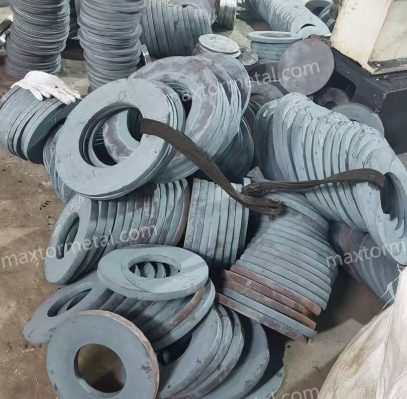
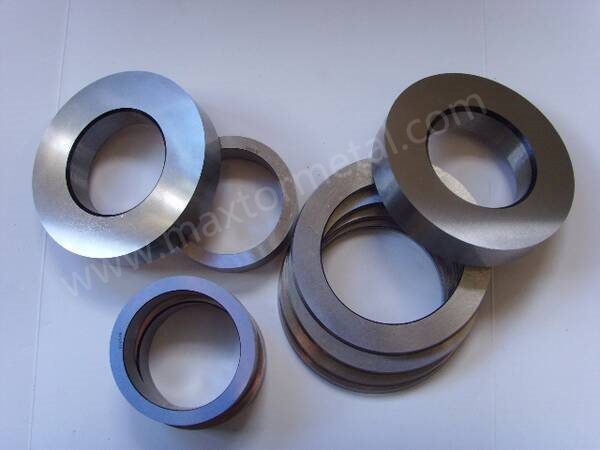
Lames de cisaille à rouleaux et couteaux circulaires de haute précision
Chez Maxtor Metal, nous fabriquons des couteaux circulaires (slitter) et des lames de cisaille à rouleaux pour les lignes de refendage haute vitesse et les cisailles de rives, où ils agissent comme des outils de coupe superposés. Grâce à des mouvements rotatifs synchronisés des lames supérieures et inférieures, ces outils réalisent un refendage longitudinal continu et sans copeaux sur des bobines de métal laminé à froid, à chaud et en alliages spéciaux avancés. Conçus pour résister à des charges dynamiques sévères, ces outils s'intègrent parfaitement aux environnements de traitement des métaux les plus exigeants au monde.
1.1 Technical Specification Matrix
Parameter Class
Technical Specification Details
Compatible Machinery
Deployed on global high-precision slitting lines and side trimmers including FIMI, SMS Group, Danieli, Andritz, Stamco, and Herr-Voss Stamco. Demands total compliance with rigid spindle systems requiring high dynamic balance and zero axial play.
* Thickness Tolerance: ±0.002 mm to ±0.005 mm (High-Precision Lines; distinct from standard ±0.01 mm commercial engineering blueprints—see Section 4.3 for deep analysis)
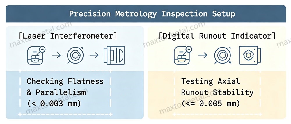
* Flatness & Parallelism: <0.003 mm to 0.005 mm
* Axial Runout: ≤0.005 mm (prevents periodic gap fluctuation and severe burrs)
* Unnoted Tolerances: Compliance with ISO 2768-mK standards.
Surface Topography
* Cutting Edge & Lateral Faces: Ra <0.2μm to 0.4μm via ultra-precision grinding and mirror polishing .
* Non-Working Surfaces: Ra <1.6μm.
Target Slitting Stock
Low-carbon cold-rolled coils, hot-rolled pickled plates, electrical silicon steel sheets, copper/aluminum alloy strips, stainless steels, and Ultra-High-Strength Steels (UHSS, yield strength ≥900 MPa, tensile strength up to ≥1200 MPa, such as automotive hot-stamped steel, martensitic steel, and DP1180).
Présentation technique des lames de cisaille à rouleaux
2.1 The Mechanics of “Shear-Heavy Compression”
Rotary slitting is not a simple separation process; it is a complex, continuous “shear-heavy compression” operation. As the metal coil passes through the overlapping upper and lower rotary blades, the material undergoes three distinct deformation phases:
Elastic Deformation: The initial contact where the knife edge indents the strip surface.
Plastic Shear: The blade penetrates deeper, forcing the material past its yield point along a localized shear plane.
Fracture Zone Initiation: Micro-cracks propagate from both the upper and lower knife tips until they meet, cleanly separating the material without chip generation.
During high-speed operations, the tool is subjected to severe cyclic mechanical impacts coupled with intense friction along the blade flanks. This localized friction generates extreme instantaneous flash temperatures. If the blade material lacks sufficient thermal stability or hot hardness, the cutting edge quickly undergoes localized tempering, leading to plastic deformation, accelerated abrasive wear, and eventual micro-chipping.
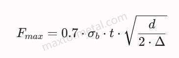
The peak shearing force per knife pair is calculated using the following empirical model:
Where:
Fmax is the peak shearing force per knife pair.
σb is the ultimate tensile strength of the strip material.
t is the strip thickness.
d is the blade outer diameter.
Δ is the total cutting engagement (penetration depth).
2.2 Microstructural Wear Diagnostics
To ensure stable tool performance, the blade microstructure must resist three primary wear mechanisms:
Adhesive Wear (Galling): Occurs predominantly when slitting soft or highly ductile materials like stainless steel or aluminum. The high pressure causes localized micro-welding between the strip and the blade flank, tearing away small particles of the blade matrix during operation.
Abrasive Wear: Caused by hard micro-constituents (such as iron oxides on hot-rolled pickled bands or highly abrasive silicon carbide structures in electrical steels) plowing into the tool steel matrix. Resistance depends entirely on the volume fraction and uniform distribution of primary alloy carbides (M6C, MC, M23C6).
Thermal Fatigue (Heat Checking): Continuous thermal cycling between ambient and flash temperatures induces cyclic tensile and compressive stresses at the cutting edge, leading to microscopic networks of perpendicular thermal cracks.
Applications industrielles des lames de cisaille à rouleaux
Work Material Profile: Dual-Phase (DP) steels, automotive hot-stamped boron steels, and martensitic steels with yield strengths ranging from 900 MPa to 1100 MPa.
Recommended Material Solution: High-Vanadium modified cold-work steel (DC53 / LD).
Engineered Clearances: Axial side clearance must be set to 14% to 18% of the sheet thickness. Setting a standard clearance under-provisions the shear plane, causing an exponential spike in cutting force that can lead to catastrophic blade fracturing.
Operational Parameter Limit: Maximum slitting speed should be regulated to 80 m/min to 120 m/min to control mechanical shock and thermal loading on the refined grain boundaries.
3.2 High-Speed Electrical Silicon Steel Slitting
Equipment Type: Ultra-precision, vibration-damped looping slitter lines running at high frequencies.
Work Material Profile: Non-oriented and grain-oriented electrical silicon steel sheets (0.20 mm to 0.50 mm thick) featuring highly abrasive silicon content.
Recommended Material Solution: Mo+W Composite Modified H13 or Performance Powder Metallurgy HSS (ASP 23).
Engineered Clearances: Axial side clearance strictly locked at 8% to 10% of the strip thickness; radial overlap controlled precisely within 2 mm to 0.4 mm.
Operational Parameter Limit: Slitting velocities up to 300 m/min to 400 m/min. Surface finishes must maintain Ra <0.2μm with a mirror polish to eliminate micro-abrasion and minimize secondary iron dust generation.
Equipment Type: Heavy-duty industrial slitter lines and side trimmers.
Work Material Profile: Hot-rolled pickled plate, carbon steel, and low-alloy structural steels with thicknesses ≥3 mm.
Recommended Material Solution: Standard H13 (4Cr5MoSiV1) or Cr-Mo-Ni Modified H13 for large diameters (>400 mm).
Engineered Clearances: Axial side clearance set to 10% to 12% of the plate thickness; radial overlap set between 6 mm and 1.0 mm to ensure complete structural separation across heavy cross-sections.
Operational Parameter Limit: Designed for heavy-impact, low-speed processing ranges (30 m/min to 60 m/min). Relies on high base impact toughness to prevent macro-chipping under high-tonnage loads.
Equipment Type: High-precision slitting lines equipped with secondary tension control loops and non-marring separating tools.
Work Material Profile: Austenitic (e.g., SUS304/316) and ferritic (e.g., SUS430) stainless steel precision strips with highly adhesive surface properties.
Recommended Material Solution: Cr-Mo-Ni Modified H13 or Matrix Steel (Caldie) combined with physical vapor deposition or special coatings.
Engineered Clearances: Side clearance set at 9% to 11% of the material thickness to compensate for the high work-hardening rate of austenitic matrices.
Operational Parameter Limit: Operating speeds of 100 m/min to 180 m/min. Utilizing DLC or advanced surface treatments prevents cold-welding and adhesive material buildup on the blade face.
Work Material Profile: High-conductivity copper strips, transformer aluminum foils, and battery-grade current collector foils down to ultra-thin gauges.
Recommended Material Solution: High-performance Powder Metallurgy Steel (ASP 23) to achieve maximum structural homogeneity.
Engineered Clearances: Ultra-low side clearances ranging from 6% to 8% of foil thickness; radial overlap minimized to 15 mm to 0.25 mm to avoid material folding.
Operational Parameter Limit: Running speeds up to 500 m/min. Requires a mirror finish (Ra ≤2μm) across both cutting flanks to eliminate localized drag and edge deformation.
Equipment Type: Standard commercial steel service center slitting equipment.
Work Material Profile: Cold-rolled commercial carbon steel coils (SPCC, SECC) with tensile strengths under 450 MPa and thicknesses between 0.5 mm and 2.0 mm.
Recommended Material Solution: Standard H13 (4Cr5MoSiV1) or Cr-Mo-V-Mo Modified H13.
Engineered Clearances: Standard side clearance fixed at 10% of the material thickness; radial overlap maintained at a constant 3 mm to 0.5 mm.
Operational Parameter Limit: Highly stable, continuous operation speeds up to 200m/min, emphasizing extended maintenance intervals and straightforward regrinding profiles.
4.Problèmes de Défaillance Courants et Solutions Techniques
4.1 Catastrophic Structural Cracking or Large-Scale Chipping
Root Cause Analysis: Using highly brittle, conventional cold-work tool steels (like D2 or SKD11) when slitting heavy-gauge plates (≥3mm) or high-strength steels under severe locking loads. These traditional steels lack sufficient fracture toughness under heavy, combined shear and compression forces, leading to deep, catastrophic transgranular cleavage failures.
Solution d'ingénierie : Transition the blade base to standard H13 (4Cr5MoSiV1) or a specialized Cr-Mo-Ni modified H13 matrix. For high-strength applications up to 1500MPa, upgrade to low-carbon high-toughness matrix steel (Caldie/Viking). This shift optimizes core impact energy absorption while maintaining a high structural yield point.
Engineering Trade-off: Increasing the base toughness usually requires reducing the volume of primary un-dissolved chromium carbides. This lowers the material’s absolute abrasive wear resistance, requiring more frequent, controlled maintenance grinding.
4.2 Rapid Edge Softening and Thermal Collapse (Mushrooming)
Root Cause Analysis: Continuous, high-speed friction along the blade flanks generates localized heat that exceeds the material’s initial tempering temperature. This triggers a microstructural conversion from tempered martensite to over-tempered ferrite, lowering the edge hardness and causing the blade profile to deform or “mushroom”.
Solution d'ingénierie : Deploy Cr-Mo-W or Mo+W composite modified H13 alloys. The synchronized additions of Tungsten (W) and Molybdenum (Mo) precipitate secondary ultra-fine M6C and MC carbides during hot processing. These carbides remain highly stable at elevated temperatures, providing excellent hot hardness and thermal fatigue resistance.
Engineering Trade-off: The high concentration of refractory elements (W, Mo) increases the material’s sensitivity to grinding burn during resharpening, requiring highly controlled grinding feeds and specialized vitrified CBN wheels.
4.3 Strip Camber, Snaking, and Inconsistent Slit Widths
Root Cause Analysis: Excessive cumulative thickness errors in the knife and spacer assembly, or severe axial runout (≥0.005mm) along the slitter arbor. This causes the relative clearance between the upper and lower knives to oscillate dynamically during rotation, shifting the shear plane and inducing lateral wandering in the strip.
Solution d'ingénierie : Implement strict micro-metric manufacturing controls to guarantee thickness tolerances within ±0.002mm and keep the axial runout under ≤0.005mm. All tooling setups should utilize high-precision ground spacers and be assembled over high-rigidity spindles.
Engineering Trade-off: Achieving these tight tolerances requires temperature-controlled grinding rooms and comprehensive metrology verification, which increases initial tooling costs.
Engineering Note: The Operational Divide Between ±0.01 mm and ±0.002 mm Thickness Tolerances
In standard mechanical blueprints, a thickness tolerance of ±0.01 mm or wider is commonly specified. However, for the high-precision applications championed in this white paper, a micron-level tolerance of ±0.002 mm to ±0.005 mm is mandatory. The critical technical factors dictating this divide include:
Multi-Knife Setup & Cumulative Error Effect: In basic slitting operations where only 2 to 5 cuts are performed per arbor, a single-knife tolerance of ±0.01 mm results in a negligible total cumulative error. However, in high-capacity, multi-knife precision lines (e.g., electrical silicon steel or ultra-thin electronic foils) requiring 20 to 50 cuts simultaneously, a ±0.01 mm tolerance compounds into a massive cumulative axial drift of ±0.2 mm to ±0.5 mm. This severely misaligns the downstream knives relative to the arbor centerline, making ultra-precise setups impossible.
Tooling Setup Dynamics: Manual Shimming vs. Automated Blind-Assembly: Conventional industrial lines operating with ±0.01 mm knives heavily rely on skilled operators to manually measure and compensate for gaps using ultra-thin copper shims (typically 0.01 mm to 0.05 mm thick) during setup. Conversely, high-automation, world-class slitting lines (such as those from FIMI, SMS Group, or Danieli) require “blind-assembly”—where knives and precision spacers are stacked sequentially onto the arbor and locked mechanically based on pure computational data, with zero manual shimming allowed. This operational paradigm mandates a strict ±0.002 mm manufacturing tolerance.
Gauge-Specific Clearance Sensitivity: The optimal axial side clearance is usually engineered at 8% to 12% of the work material thickness. For heavy-gauge plates (≥3 mm), the nominal clearance spans hundreds of microns, rendering a ±0.01 mm knife thickness variation statistically insignificant. However, when slitting ultra-thin foils or electrical steels (≤0.1 mm), the ideal side clearance drops to approximately 0.01 mm. Under these extreme bounds, a ±0.01 mm knife tolerance will either close the gap to zero (causing immediate blade collision and edge chipping) or double it (causing severe vertical burrs and material deformation).
Manufacturing Feasibility & Asset Lifecycle TCO: Producing a knife with a ±0.01 mm tolerance requires only standard precision surface grinding. Achieving a reliable ±0.002 mm tolerance requires climate-controlled grinding facilities (to eliminate thermal expansion drift), deep cryogenic treatment (to stabilize the microstructure against residual stress warping), and sequential mirror lapping. While ultra-precision tooling demands a higher initial capital expenditure, it eliminates manual shimming downtime, protects high-cost arbor bearings from dynamic axial imbalances, and delivers a substantially lower Total Cost of Ownership (TCO) in high-throughput lines. For teams commissioning or auditing a new knife stack, the OEM Slitter Knife Spindle Fit Audit Checklist provides a structured workflow for verifying ISO bore fits, TIR gates, and spacer parallelism before the tooling touches coil.
4.4 Excessive Secondary Burr Formation on Strip Edges
Root Cause Analysis: The horizontal clearance between the upper and lower blades has widened beyond the optimal material deformation limits, or the blade edges have undergone micro-chipping. This forces the material to undergo tearing and tensile failure rather than clean shearing, leaving thick, vertical burrs along the bottom edge of the strip.
Solution d'ingénierie : Readjust the horizontal clearance to match the specific material criteria (e.g., 8%–12% for soft carbon steels, 14%–18% for high-strength steels). If the burrs are caused by micro-abrasion of the blade edge, upgrade to an atomized Powder Metallurgy steel (ASP 23) to ensure a highly uniform carbide structure at the micron level.
Engineering Trade-off: Setting tighter clearance profiles demands exceptional machine stiffness and precise operator alignment, as any deflection can cause the blades to rub, accelerating tool wear.
4.5 Micro-Crack Propagation from Flank Wear (Heat Checking)
Root Cause Analysis: Repeated thermal shocks where the blade edge heats up rapidly in the cut and cools outside the cut create cyclic thermal stresses. This leads to the formation of micro-cracks perpendicular to the cutting edge, which can grow into large chips over time.
Solution d'ingénierie : Utilize a Cr-Mo-V-Mo modified H13 steel with elevated Molybdenum content to enhance tempering stability and refine grain structures. Additionally, integrate deep cryogenic treatment down to -196℃ post-quenching to relieve residual micro-stresses and prevent sub-surface crack initiation.
Engineering Trade-off: The added thermal fatigue resistance slightly lowers the maximum achievable room-temperature hardness, reducing the tool’s effectiveness when slitting highly abrasive surfaces.
4.6 Edge Galling and Material Pickup when Slitting Aluminum/Stainless
Root Cause Analysis: Severe adhesive wear forces soft, ductile materials to cold-weld onto the unprotected carbon steel matrix of the knife flank. As the strip moves past, these adhered fragments break free, pulling tiny chunks of the tool steel matrix with them and scratching the slitted product.
Solution d'ingénierie : Apply an ultra-smooth Diamond-Like Carbon (DLC) coating or a thin chromium-nitride layer to the blade flanks. Ensure the cutting edge and faces are mirror-polished to a surface finish of Ra <0.2μm to minimize physical mechanical locking points.
Engineering Trade-off: Thin, hard coatings like DLC are susceptible to peeling if the underlying steel matrix deforms under heavy impact, meaning they can only be applied to highly rigid base materials.
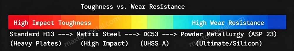
5.Guide d'Ingénierie des Matériaux
The performance of a rotary slitter knife depends heavily on its underlying alloy chemistry and carbide morphology. Standard cold-work steels like D2 and SKD11 feature large, coarse primary chromium eutectic carbides (M7C3). Under the high cyclic compression loads of modern slitting lines, these large carbides act as structural stress concentrators, often leading to catastrophic edge chipping or sudden cracking. To address these challenges, advanced tool steels utilize tailored alloying strategies:
5.1 Standard H13 (4Cr5MoSiV1)
A medium-carbon, high-chromium hot-work steel featuring an exceptionally tough, dislocation-tempered martensitic matrix. It relies on a balanced Cr-Mo-V composition to deliver excellent impact energy absorption and resistance to thermal shock, making it an ideal choice for heavy-gauge hot-rolled processing lines. However, its lower volume fraction of primary hard carbides limits its long-term resistance to abrasive wear.
5.2 Modified H13 Variants (Co-Alloying Schemes)
Cr-Mo-W System (+W): Micro-additions of Tungsten form highly stable, hard M6C complex carbides. This modification significantly boosts secondary hardening peaks, hot hardness, and edge retention without sacrificing base impact toughness, making it well-suited for high-frequency silicon steel slitting.
Cr-Mo-Ni System (+Ni): Nickel additions strengthen the martensitic matrix through solid solution strengthening, lowering the ductile-to-brittle transition temperature and improving transverse mechanical properties. This modification helps prevent catastrophic axial cracking in large-diameter tools (>400mm) subjected to high lateral clamping forces.
Cr-Mo-V-Mo System (High Mo): Increasing the Molybdenum ratio improves grain refinement and significantly enhances tempering resistance. This structure resists thermal softening and micro-crack propagation under continuous, high-speed friction.
W+Ni Composite System: Combines the high-hardness precipitation of Tungsten carbides with the matrix-strengthening properties of Nickel. This dual approach creates an excellent balance of deformation resistance and toughness, ideal for slitting uneven or warped metal strips.
Mo+W Composite System: Leverages a balanced combination of Molybdenum and Tungsten to maximize thermal stability and grain refinement. This composition provides excellent hot hardness and thermal fatigue resistance during the high-speed slitting of ultra-thin electrical steels.
An advanced cold-work steel developed to overcome the toughness limitations of standard SKD11/D2 alloys. By increasing the Vanadium (V) content, it forms fine, evenly dispersed MC-type vanadium carbides that refine the grain structure. At an operating hardness of HRC 60–62, DC53 provides twice the impact toughness of SKD11, substantially reducing the risk of edge chipping when processing high-strength automotive sheets up to 1100MPa.
5.4 Matrix Steels (Caldie / Viking)
Engineered with a low-carbon, high-alloy matrix formula that minimizes the formation of large, brittle eutectic carbides during solidification. These steels combine the high matrix hardness of a high-speed steel (HRC 59–61) with the excellent impact ductility of an H13 hot-work alloy. This makes them highly effective at resisting fatigue cracking and structural failure under severe mechanical loads (1100MPa to 1500MPa).
Produced via gas atomization and Hot Isostatic Pressing (HIP), this process bypasses conventional ingot casting to eliminate carbide segregation. The resulting microstructure consists of an ultra-fine, highly uniform dispersion of sub-micron vanadium and tungsten carbides embedded within a high-alloy matrix. Operating at HRC 62–64, these materials offer an excellent combination of abrasive wear resistance, compressive strength, and toughness. For high-demand, automated slitting lines, PM steels can extend tool life by 5 to 10 times compared to standard H13 alloys.
6.Traitement Thermique et Équilibre de Dureté
6.1 Vacuum Thermal Hardening and Tempering Operations
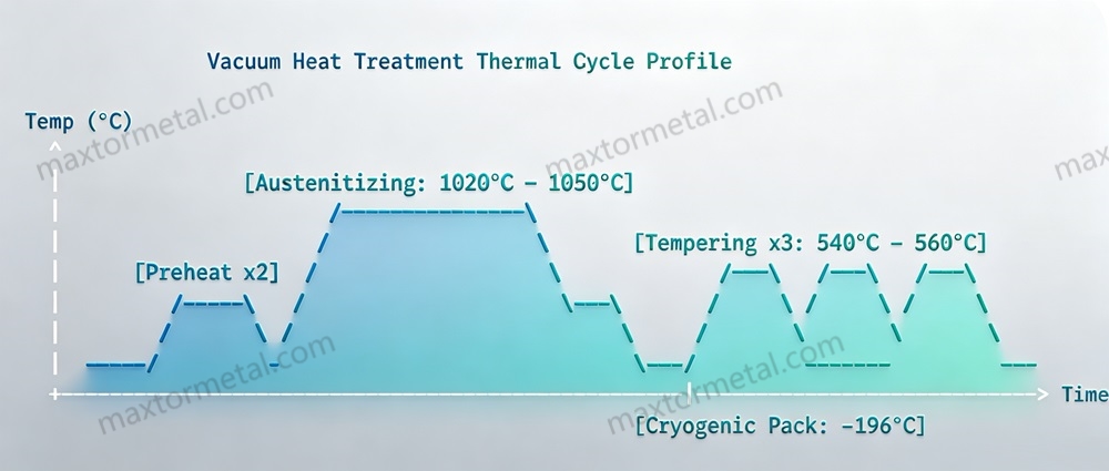
Achieving the proper balance between wear resistance and structural toughness requires precise control over the heat treatment process. Maxtor Metal’s standard thermal hardening cycle for high-alloy rotary slitter knives includes:
Double Stage Pre-heating: Blades are heated slowly to 550℃ and then to 850℃ inside a high-vacuum furnace (10-4 mbar). This minimizes thermal stress gradients and prevents distortion across the blade’s geometry.
High-Temperature Austenitizing: The temperature is raised to the material’s specific austenitizing range (typically 1020℃ to 1050℃ for modified H13 alloys; up to 1180℃ for PM variants) to dissolve alloy elements into the parent austenite matrix while preserving refined grain boundaries.
Controlled Gas Quenching: High-pressure nitrogen gas (4 bar to 10 bar) is forced through the chamber to quench the blades rapidly, transforming the austenite into a hard, un-tempered martensitic structure.
Triple Sub-Critical Tempering: To relieve internal quenching stresses and optimize toughness, the knives undergo at least three separate tempering cycles at temperatures ranging from 540℃ to 560^℃. This process triggers secondary hardening by precipitating fine alloy carbides and converts unstable retained austenite into stable tempered martensite.
6.2 Deep Cryogenic Treatment Mechanics
Deep cryogenic processing is highly recommended for high-performance slitting operations. Immediately following the initial gas quench, the blades are cooled gradually inside a specialized cryogenic chamber down to -196℃ and held at this temperature for 24 to 36 hours.
Complete Austenite Conversion: This process drives the transformation of remaining unstable retained austenite into hard martensite, eliminating structural weak points that can cause dimensional shifting or warping during operation.
Eta (η) Carbide Precipitation: Cryogenic conditioning creates micro-structural stresses that encourage the precipitation of ultra-fine, nano-scale eta-carbides during subsequent tempering stages. This significantly improves the tool’s micro-abrasive wear resistance and helps maintain a sharp cutting edge over extended production runs.
6.3 Duplex Plasma Nitriding Profiles
For challenging slitting applications, such as processing abrasive silicon steels or heavy-gauge carbon plates, the blades can undergo a duplex plasma nitriding treatment. Conducted in a vacuum chamber using an ionized hydrogen-nitrogen gas mixture at temperatures below the tempering point (480℃ to 500℃), this process introduces atomic nitrogen into the steel’s surface lattice.
Case Depth Control: Creates a highly controlled diffusion zone with a depth of 05 mm to 0.10 mm.
Surface-to-Core Hardness Gradient: The process yields a hard surface shell rated at HV 900–1100, while the core maintains its high toughness and impact resistance (HRC 54–57). This design successfully addresses the engineering challenge of combining high external wear resistance with high internal impact absorption.
7.Géométrie de la Lame et Ingénierie du Tranchant
The precision of a rotary slitting operation depends directly on maintaining correct geometric clearances and edge configurations:
7.1 Axial Side Clearance (Δx)
The horizontal gap between the upper and lower shearing edges is a critical parameter.
Standard Gauge Steels: Set between 8% and 12% of the material thickness. If the clearance is too small, the upper and lower fracture lines will pass each other, causing secondary shearing, high material friction, and fast edge wear. If the gap is too large, the material will undergo tensile tearing, leaving thick, heavy burrs.
Ultra-High-Strength Steels (UHSS): The side clearance must be increased to 14% to 18% of the sheet thickness. Because high-strength materials resist plastic deformation, a wider clearance is needed to let the shear cracks propagate naturally, preventing extreme force spikes that could crack or chip the blade.
7.2 Radial Overlap (ho)
The vertical engagement depth of the upper and lower blades is adjusted based on the material thickness and strength.
Thin Strip Materials (<0.5mm): Typically requires a small positive overlap (2 mm to 0.4 mm) to ensure complete separation across the entire width of the cut.
Heavy-Gauge Plates (≥3mm): The vertical overlap can be expanded up to 0 mm to ensure reliable material separation. This requires a highly rigid spindle system to prevent the knives from deflecting or backing off under load.
7.3 Edge Profiling and Micro-Beveling
Standard sharp, 90°square edges are prone to micro-chipping when subjected to high impact forces. To prevent this, Maxtor Metal uses specialized edge conditioning:
Micro-Honing: The sharp edge is lightly honed using fine diamond media to create a uniform radius of 5μm to 15μm. This provides extra support to the cutting edge, reducing localized stress concentrations without increasing burr formation.
Flank Micro-Beveling (45°Protective Chamfer): For heavy-duty slitting operations, a tiny 0.05mm*45°protective chamfer is ground onto the cutting corner. This redirecting feature helps absorb high impact forces and prevents edge chipping caused by material variations or line vibrations.
8.Processus de Fabrication et Inspection de la Qualité
Every rotary slitter knife is manufactured through a precise sequence of operations to ensure exceptional dimensional accuracy and structural integrity:
8.1 Material Forging
Multi-Directional Forging: Ingots are forged using high-tonnage hydraulic presses across three dimensions, achieving a minimum forging reduction ratio of 5:1. This collapses dendritic structures and refines grain distributions.
8.2 Rough Machining & Stress Relieving
CNC Turning: Forged blanks are rough-turned to within +1.5mm of final dimensions, and center bores are pre-machined.
Stress-Relief Annealing: To eliminate residual stresses induced by forging and heavy machining, parts are heated to 650℃, held for 4 hours, and slowly cooled in the furnace. This ensures excellent dimensional stability during subsequent heat treatment.
8.3 Heat Treatment & Cryogenic Processing (refer to Section 6 for full cycle details)
Blanks undergo vacuum gas hardening and deep cryogenic cycling down to -196℃, as detailed in Section 6. This achieves the target hardness profile while minimizing internal material stresses.
8.4 Precision Grinding & Metrology Verification
Rotary Surface Grinding: Blade faces are ground on high-precision rotary grinders equipped with hydrostatic spindles and automated thermal compensation systems.
Bore Grinding: The internal center bore is ground to tight tolerances (typically H5, +0.011 / -0mm) to ensure a precise slip-fit onto the slitter arbor, minimizing radial play.
Dual-Face Mirror Lapping: Working flanks undergo a sequential lapping process using diamond slurries to achieve a surface roughness of Ra <0.2μm. This eliminates grinding marks and provides a mirror finish that reduces friction and prevents material adhesion.
8.5 Final Quality Inspection Protocols
Dimensional Inspection: Thickness and parallelism are verified inside a climate-controlled metrology room (20℃±5℃) using laser interferometers and high-precision digital indicators. Parallelism must measure under 0.003mm to ensure uniform cutting clearance.
Axial Runout Testing: The finished knife is mounted on a certified reference mandrel and rotated under a high-resolution digital gauge to verify that axial runout remains ≤0.005mm.
Non-Destructive Testing (NDT): Every blade undergoes Magnetic Particle Inspection (MPI) or Liquid Penetrant Testing (LPI) across the cutting edges to confirm the total absence of micro-cracks or grinding burns.
9. Études de Cas
Case Study 1: Resolving Edge Failure in an Automotive UHSS Slitting Line
The following data comes from Maxtor Metal’s project support for automotive steel service center, the customer name has been anonymized.
Customer Profile: A major tier-1 automotive steel service center processing advanced high-strength steels.
The Challenge: The facility was using conventional D2/SKD11 rotary knives to slit 1.6mm thick DP1180 high-strength steel coils. The blades suffered from frequent, unpredictable micro-chipping and large-scale fracturing along the cutting edges. This required the line to be shut down for knife changes every 12,000 meters of production, resulting in low equipment efficiency and high maintenance costs.
Engineering Intervention: Maxtor Metal’s application engineering analyzed the application and replaced the brittle D2 knives with DC53 High-Vanadium cold-work steel blades heat-treated to HRC 60–62. The new setup included deep cryogenic treatment to eliminate internal material stresses. Additionally, the horizontal cutting clearance was increased from a standard 10% up to 16% of the sheet thickness to accommodate the material’s high yield strength.
Quantifiable Results:
Tool Life Extension: Single-line slitting distance increased from 12,000 meters to over 25,000 meters before requiring a regrind.
Chipping Reduction: Catastrophic blade cracking was completely eliminated.
Économies de coûts : Reduced annual tooling costs by 52% and decreased weekly downtime hours by 78%. (The reduction in catastrophic chipping events eliminated unplanned line stoppages, which accounted for the disproportionate reduction in downtime relative to knife life extension.)
Case Study 2: Eliminating Edge Softening and Burr Issues in Silicon Steel Slitting
The following data comes from Maxtor Metal’s project support for a motor laminations manufacturer, the customer name has been anonymized.
Customer Profile: A manufacturer of high-efficiency electrical transformers and electric vehicle motor laminations.
The Challenge: The plant was slitting ultra-thin, highly abrasive 0.35mm grain-oriented electrical silicon steel coils at a high speed of 250m/min. They used standard H13 tool steel blades, which suffered from rapid thermal softening and edge wear due to the high friction heat generated during operation. This led to excessive edge burrs (>0.05mm), causing the slitted strips to fail insulation tests.
Engineering Intervention: Maxtor Metal implemented a Mo+W Composite Modified H13 tool steel solution, hardened to HRC 58–60. The blades underwent an advanced vacuum heat treatment process followed by a 08 mm deep plasma nitriding cycle to create a hard surface shell (HV 1000) over a tough core. The blade faces were also mirror-polished to a surface finish of Ra 0.15μm to minimize friction.
Quantifiable Results:
Qualité des bords : Edge burrs were maintained consistently under 015 mm, passing all quality checks.
Regrind Intervals: The continuous production volume between blade regrinds extended from 35,000 meters to 210,000 meters. (The extended interval reflects the particularly aggressive abrasive wear mode of silicon steel, where surface treatment and alloy selection have a compounding effect on tool life.)
Dust Reduction: Highly polished blade flanks minimized friction, significantly reducing airborne iron dust along the slitting line.
Foire aux questions (FAQ)
Question: Pourquoi devrions-nous utiliser des aciers à outils H13 modifiés plutôt que les aciers conventionnels D2/SKD11 pour le refendage de métaux lourds ?
A1 : Les aciers conventionnels D2/SKD11 présentent des carbures de chrome (M7C37C3) larges et fragiles dans leur microstructure. Lorsqu'ils sont soumis aux forces de compression et d'impact cycliques élevées des lignes de refendage modernes, ces grands carbures agissent comme des concentrateurs de contraintes, provoquant souvent des fissures soudaines sur le tranchant ou une défaillance catastrophique de la lame. Les aciers H13 modifiés utilisent une matrice martensitique plus tenace et uniforme qui résiste à la fissuration sous de lourdes charges, ce qui en fait un choix beaucoup plus fiable pour les applications exigeantes.
Question: Comment une micro-addition de tungstène (W) améliore-t-elle les performances des couteaux de refendage H13 ?
A2: Lors du traitement thermique, le tungstène se combine au carbone pour former des carbures fins et durs de type M66C. Ces micro-carbures augmentent la réponse au durcissement secondaire du matériau et maintiennent une dureté élevée à haute température, empêchant le tranchant de s'amollir en raison de la chaleur de friction lors du refendage à haute vitesse.
Question: Quel rôle joue le nickel (Ni) dans les lames de cisaille à rouleaux de grand diamètre ?
A3: Le nickel renforce la matrice d'acier par durcissement en solution solide, ce qui améliore la ténacité aux chocs à basse température et les propriétés mécaniques transversales. Pour les lames de grand diamètre (>400 mm), cette ténacité supplémentaire empêche l'outil de se fissurer axialement sous des forces de serrage latéral élevées.
Question: Quand est-il nécessaire de passer à des aciers issus de la métallurgie des poudres (PM) haute performance comme l'ASP 23 ?
A4: Les aciers PM sont fortement recommandés pour les lignes de refendage automatisées à haut volume ou lors du traitement de matériaux fins et abrasifs tels que les aciers électriques au silicium, où la qualité du bord est critique. Le procédé de métallurgie des poudres élimine la ségrégation des carbures, créant une structure exceptionnellement uniforme qui prévient les micro-ébréchures et prolonge la durée de vie de l'outil de 5 à 10 fois par rapport aux aciers conventionnels.
Question: Quelle est la cause principale des bords ondulés ou en forme de serpent sur une bande refendue ?
A5: Les bords ondulés sont généralement causés par un jeu de coupe instable pendant le fonctionnement, souvent dû à un faux-rond axial (runout) supérieur à ≤0,005 mm ou à des variations d'épaisseur cumulées dans l'assemblage des lames et des entretoises. Cela permet aux couteaux d'osciller légèrement pendant leur rotation, ce qui fait varier dynamiquement le jeu horizontal et fait dévier la coupe.
Question: Comment les variations de tolérances d'épaisseur affectent-elles une configuration de refendage multi-lames ?
A6: Sur un arbre de refendage équipé de plusieurs lames et entretoises, les erreurs d'épaisseur individuelles s'accumulent sur l'ensemble de l'assemblage. Si les tolérances des lames individuelles ne sont pas maintenues entre ±0,002 mm et ±0,005 mm, l'erreur totale accumulée désalignera les couteaux supérieurs et inférieurs, entraînant des jeux de coupe irréguliers, une mauvaise qualité de chant et une usure prématurée des outils.
Question: Pourquoi les aciers automobiles à ultra-haute résistance nécessitent-ils des jeux de coupe horizontaux plus larges ?
A7: Les matériaux à haute résistance possèdent des limites d'élasticité élevées et une faible ductilité. Si vous utilisez un jeu standard de 10 %, le matériau ne se fracturera pas proprement, provoquant un pic massif de force de coupe qui peut rapidement émousser ou ébrécher la lame. Augmenter le jeu à 14 %–18 % permet aux fissures de cisaillement de se rejoindre naturellement, assurant une séparation nette avec moins de contrainte sur l'outil.
Question: Quels sont les avantages du traitement cryogénique profond à -196°C pour les couteaux circulaires ?
A8: Le traitement cryogénique transforme l'austénite résiduelle instable restante en martensite revenue stable et favorise la précipitation d'eta-carbures ultrafins. Cela améliore la stabilité dimensionnelle de l'outil, soulage les contraintes internes et garantit que le jeu de coupe ne dérive pas lors de longues séries de production à haute vitesse.
Question: Quel est le but de la nitruration plasma sur une lame de refendage, et cela rend-il l'outil cassant ?
A9: La nitruration plasma diffuse de l'azote dans la surface de la lame pour créer une couche externe dure et résistante à l'usure (0,05–0,10 mm de profondeur, HV 900–1100) tout en gardant le cœur tenace et résistant aux chocs. Comme la couche nitrurée est mince et soutenue par un cœur robuste, elle améliore considérablement la résistance à l'usure sans rendre toute la lame cassante.
Question: Comment une face latérale polie miroir (Ra < 0,2 µm) améliore-t-elle les performances de coupe ?
A10: Un fini miroir élimine les micro-traces de meulage où les fissures peuvent commencer, minimise la friction contre la bande en mouvement et aide à empêcher les métaux mous de coller à l'outil. Il réduit également la traînée de friction et limite l'accumulation de poussière de fer le long de la ligne.
Question: Les revêtements DLC (Diamond-Like Carbon) peuvent-ils être utilisés pour le refendage d'aciers à haute résistance ?
A11: En général, non. Bien que les revêtements DLC offrent un coefficient de frottement exceptionnellement bas, ils sont très fins et rigides. Sous les forces de compression extrêmes requises pour refendre des aciers à haute résistance, la matrice d'acier sous-jacente peut fléchir légèrement, provoquant la fissuration et l'écaillage du revêtement DLC fragile. Le DLC est mieux adapté aux matériaux mous et collants comme l'aluminium ou le cuivre.
Question: Quel est le chevauchement radial vertical idéal pour le refendage de tôles en acier au carbone moyen ?
A12: Pour les tôles en acier au carbone standard (1,0 mm à 2,5 mm d'épaisseur), le chevauchement radial vertical optimal se situe entre 0,3 mm et 0,6 mm. Cette profondeur permet d'obtenir une coupe nette sans exercer de contrainte inutile sur les roulements de l'arbre de la refendeuse.
Question: Comment pouvons-nous éviter l'écaillage des bords lors du refendage de bobines d'acier voilées ou non planes ?
A13: Les bobines voilées créent des mouvements latéraux imprévisibles et des forces d'impact inégales lors de leur passage à travers les lames. Pour ces conditions, l'acier à outils H13 modifié au W+Ni est recommandé. Il offre une grande ténacité de matrice pour absorber les chocs soudains, combiné à un petit micro-chanfrein de protection sur l'arête de coupe.
Question: Quels sont les critères de fabrication standard sans tolérance pour les dimensions non critiques des couteaux ?
A14: Toutes les dimensions non critiques ou non spécifiées sont fabriquées conformément aux normes ISO 2768-mK, garantissant une qualité constante pour chaque pièce.
Question: À quelle fréquence les couteaux de refendage rotatifs doivent-ils être inspectés pour détecter des micro-fissures lors de la maintenance ?
A15: Les couteaux doivent être soigneusement nettoyés et inspectés par contrôle magnétoscopique (MPI) à chaque cycle d'affûtage programmé. Meuler par-dessus des micro-fissures existantes sans les éliminer complètement peut entraîner l'approfondissement des fissures, provoquant une défaillance soudaine du couteau lorsque l'outil est remis en service.
Question: Quel type de meule est recommandé pour le réaffûtage des couteaux en H13 modifié ?
A16: Il est recommandé d'utiliser des meules en Nitrure de Bore Cubique (CBN) à liant vitrifié, utilisées avec un liquide de refroidissement synthétique soluble dans l'eau à haut débit. Évitez d'utiliser des meules conventionnelles en oxyde d'aluminium avec des avances importantes, car la chaleur de friction générée peut facilement provoquer un revenu localisé et des brûlures de meulage sur l'acier à outils.
Question: Pourquoi une tolérance d'alésage serrée est-elle importante pour les lignes de refendage à haute vitesse ?
A17: L'alésage central est généralement fabriqué avec une tolérance H5 pour assurer un ajustement serré et précis sur l'arbre de la refendeuse. Tout jeu excessif entre l'alésage et l'arbre provoquera une rotation légèrement excentrée du couteau, entraînant des variations cycliques du chevauchement radial et créant une coupe irrégulière avec des bavures intermittentes.
Question: Qu'est-ce qui cause la génération importante de poussière de fer autour de l'ensemble de refendage ?
A18: L'excès de poussière de fer est généralement causé par le frottement du matériau contre des flancs de lame rugueux (Ra >0,8 μm) ou par l'utilisation d'un jeu trop serré, ce qui broie les bords coupés. Le passage à des faces de lame polies miroir (Ra <0,2 μm) réduit considérablement cette friction et diminue la quantité de poussière.
Question: Comment choisir entre l'acier de matrice (Caldie) et l'acier de métallurgie des poudres (ASP 23) ?
A19: Choisissez l'acier de matrice si votre défi principal est la fissuration des lames ou les chocs mécaniques importants dus à des plaques épaisses et dures. Choisissez l'acier de métallurgie des poudres si votre objectif principal est la résistance à l'usure à long terme et le maintien d'une arête très propre et sans bavure sur les lignes à haute vitesse.
Question: Les aciers à outils pour travail à chaud standard peuvent-ils être utilisés pour des applications de refendage à froid ?
A20: Oui. L'acier H13 standard est un acier pour travail à chaud, mais sa grande ténacité aux chocs, son excellente ductilité et sa résistance à la fatigue thermique en font un matériau de base exceptionnel pour les lignes de refendage d'acier au carbone laminé à froid et à chaud.
Technical Reviewed by: Senior Metallurgical Specialist at Maxtor Metal.
Choisir Nanjing Metal IndustrialLes lames de cisaille rotatives pour une production de refendage de métal plus efficace et précise, et profitez de l'assurance de performances durables et de haute qualité.
Profitez de la commodité d'une importation fluide. Du transport au dédouanement, nous gérons l'ensemble du processus. Il vous suffit de payer la TVA et d'attendre l'arrivée de vos marchandises.
Prix Compétitifs
Nous avons vu nos lames exceller dans d'innombrables applications et sommes prêts pour tout projet que vous nous confierez. Attendez-vous à la précision, à la durabilité et à des prix compétitifs inégalés.
ODM & OEM Disponibles
Que vous fournissiez des dessins, des croquis ou des échantillons, nous pouvons concevoir et fabriquer pour vous. Nous avons également la capacité d'aider à modifier les conceptions et spécifications existantes pour améliorer presque toutes les applications d'outillage industriel. Veuillez contacter notre équipe de vente dédiée pour discuter de vos besoins spécifiques.
Contrôle Qualité Rigoureux
Une série de tests et d'inspections sont effectués pour contrôler la qualité, incluant l'inspection du premier article, l'inspection des matériaux entrants et les matériaux certifiés, l'inspection qualité en cours de production, et l'inspection qualité finale.
Approvisionnement Flexible, Coopération Illimitée
Que vous soyez un importateur, un distributeur, un grossiste ou un utilisateur final, nous vous accueillons. Bénéficiez de faibles quantités minimales de commande (MOQ), de demandes sans tracas et d'une plus grande liberté d'achat.
Suivi en Temps Réel de l'Avancement de la Production
Considérez-nous comme votre moniteur exclusif. Nous vous fournirons régulièrement des mises à jour sur chaque étape cruciale de votre chaîne de production. Quelle que soit la distance, vous aurez un aperçu en temps réel de l'avancement de votre produit.