Punti chiave
- Burr height and slit width repeatability are usually “setup + stack” problems: clearance/overlap windows only stay stable if the knife-and-spacer stack stays rigid and true.
- Slitter spacer thickness tolerance doesn’t just affect one lane—it accumulates across the arbor. Stack-up is the hidden reason widths drift when the line runs fast.
- If you want predictable edge quality, treat spacers like precision parts: control spessore, parallelism, E surface condition, then verify arbor TIR before you blame the material.
- Why burr height and slit width repeatability decide scrap, rework, and OEE
Burrs aren’t only a cosmetic defect. In film, foil, textiles, and coated webs, a rough edge can drive downstream breaks, wrinkling, poor winding, and customer complaints. In metals, burrs can trigger handling injuries, fit-up problems, and premature wear in downstream forming.
Slit width drift is just as expensive. If you can’t hold width lot-to-lot or shift-to-shift, you either widen specs (scrap risk moves downstream) or you rework (time and labor). In both cases OEE takes a hit: more stops, more inspections, and longer changeovers.
How knives and slitter spacers jointly set clearance, overlap, and rigidity
Knives create the shearing action, but spacers decide where that action happens and whether it stays stable. In a shafted setup—especially wrap shear—spacers and knives are stacked to act like a single, solid assembly. That stack stiffness is what keeps clearance and overlap from “walking” during a run.
If you want a quick refresher on the system view, see MAXTOR METAL’s guide on how knives and spacers work together—it’s a useful mental model before you start chasing individual symptoms.
What readers will learn: tolerances, setup targets, metrology, and TCO logic
This article lays out:
- the fundamentals behind burr formation and width control
- which tolerances matter most (and which ones are noise)
- setup targets you can record and repeat
- a metrology sequence that catches stack-up and runout early
- a simple TCO lens for deciding when “cheap spacers” are the most expensive parts on the machine
Precision fundamentals
Burr formation basics
Shear slitting is a scissors-like cut: two edges meet at an angle and the material fails in a controlled way. When the geometry is right, the cut is clean. When it’s wrong, you get rollover, tearing, or a burr that grows as the cut transitions from shear to fracture.
Wrap slitting generally produces cleaner edges because the web is supported as it wraps around the female knife. PFFC explains the mechanism and why wrap support reduces tearing in “Shear Slitting Can Provide Advantages” (PFFC).
The practical takeaway: burr is often the symptom of a clearance/overlap window that is unstable—because the stack flexes, the knives aren’t truly parallel, or runout changes the effective clearance around the rotation.
Slit width control physics
Slit width comes from knife position and the stability of that position under load. In a stacked system, the “positioning device” is the spacer set. If the spacers vary, the knives move. If the stack isn’t rigid, knives deflect and effective width changes.
Wrap shear systems are widely used when tight width tolerance is required because the female knives are stacked with spacers on a shaft, removing gaps and supporting the web. Parkinson Technologies describes how this configuration can achieve very tight slit width tolerances in “Achieving Tight Tolerances with Wrap Shear Slitting” (Parkinson Technologies).
So width control isn’t “just” a setting—it’s the sum of:
- spacer thickness accuracy (stack-up)
- knife and arbor runout (true running)
- stack rigidity (torque, cleanliness, contact condition)
- process stability (tension, speed synchronization, wear)
Tolerances that matter
When you’re chasing width repeatability and burr control, focus your tolerance budget where it actually changes cut geometry:
- Spacer thickness tolerance and matching (stack-up driver)
- Knife parallelism (tilt changes clearance across the width)
- Arbor runout / TIR (changes clearance and overlap around the rotation)
- Surface finish and cleanliness on contact faces (affects how “solid” the stack really is)
From a drawings-and-inspection standpoint, these characteristics map cleanly to the ISO GPS tolerancing language for form/orientation/run-out (see ISO 1101:2017).
For broader context on typical tooling tolerance discussions (for example, OD tolerance ranges often cited in slitter tooling), see “Tolerance on Slitter Tooling” (Deetee).
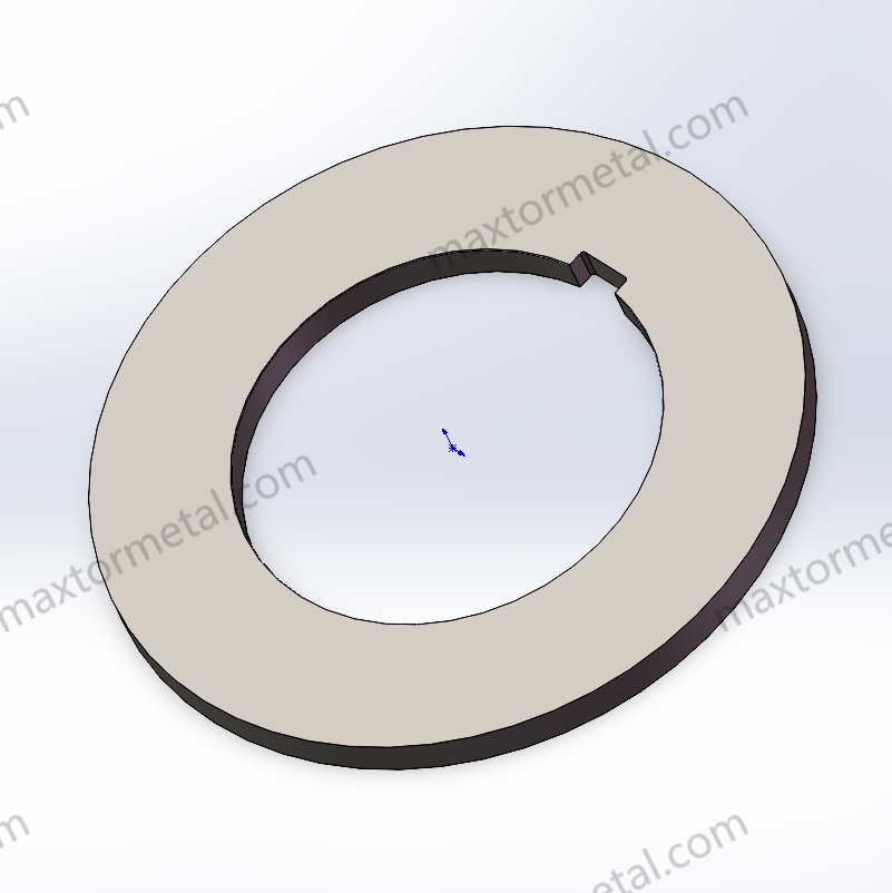
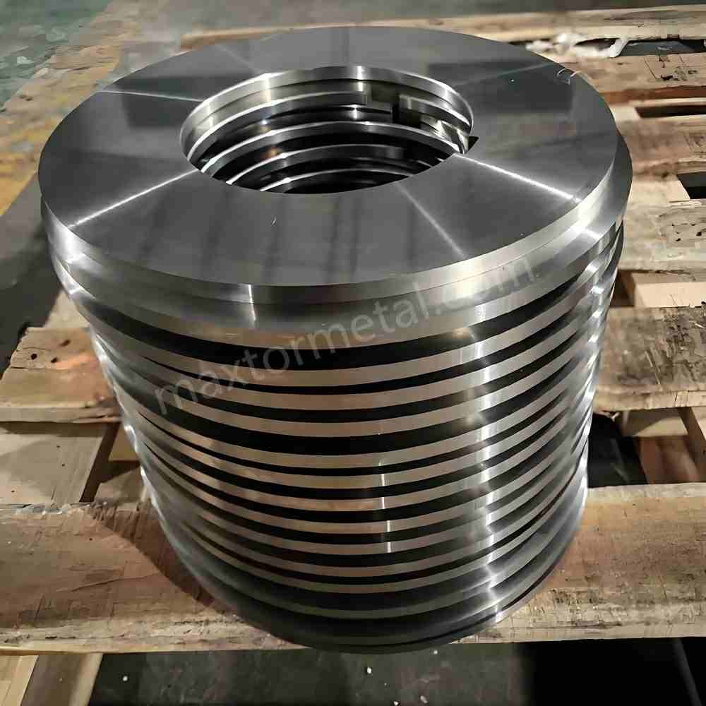
Slitter spacers precision

Thickness tolerance and stack‑up
Spacer thickness tolerance is the most direct lever on slit width accuracy.
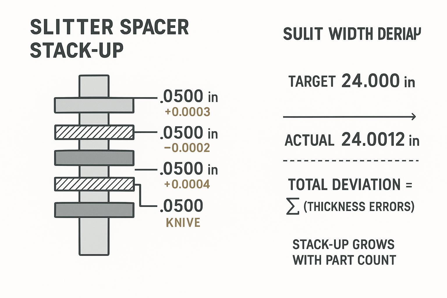
A single spacer that is 0.0003 in thick doesn’t sound like a problem—until you have many of them on one arbor. In a stacked assembly, slit width error isn’t random; it accumulates. That’s why two stacks built from “within tolerance” parts can still produce different widths.
Here’s the mental model you want on the shop floor:
- Each spacer has an actual thickness.
- Slit width at a given lane is the sum of the stack up to that knife position.
- Total deviation is the sum of the thickness errors.
If your target repeatability is ±0.002–0.005 in, you can’t treat spacers as commodity rings. You need either:
- tighter thickness tolerances, or
- fewer parts per pocket, or
- a matched set approach where actual thickness values are measured and grouped to control the summed error.
Parallelism and surface finish
Thickness is only half the story. Even if thickness is perfect, poor parallelism turns spacers into wedges.
What that does in practice:
- tilts knives slightly, so clearance isn’t uniform from operator side to drive side
- changes where the edges “meet,” which changes burr behavior
- increases vibration and micro-chatter because the stack faces don’t seat consistently
Surface finish matters because contact faces are part of the structure. A rough face can trap debris and create point contact. In a slitting stack, point contact becomes movement under load—movement becomes clearance drift—drift becomes burr.
If you specify surface texture using Ra, you’ll get the most consistent communication when your drawing notes follow the ISO GPS “surface texture, profile method” language (see ISO 4287:1997 for parameters such as Ra, and ISO 4288:1996 for assessment rules).
Matched sets and documentation
Matched sets are the cleanest way to reduce stack-up without turning every changeover into a rework exercise.
A practical matched-set package should include:
- actual thickness measurements (not just nominal)
- identification for each spacer (set ID / lane ID)
- a simple stack plan for common slit patterns
- traceability (lot/batch identifiers) so repeat performance can be audited
This is also where supplier discipline directly affects your risk.
MAXTOR METAL can support procurement teams with matched-set reports (actual measured thickness data by set) and one-stop import traceability so the set ID, inspection record, and shipment documents stay linked. The value is not marketing—it’s control: when a width issue shows up, you can isolate whether the problem is setup, wear, or a specific spacer/knife lot.
Knife materials and edges

Steel, PM, and carbide choices
Knife material affects edge retention and how long your “known good” clearance window stays stable.
- Tool steels are common for general service where toughness matters.
- PM (powder metallurgy) steels are often chosen when you need improved wear resistance without giving up all toughness.
- Carburo can be appropriate for highly abrasive materials or when edge life is the dominating cost, but it demands rigid setup and careful handling.
Material choice doesn’t replace setup discipline. It just changes how fast a marginal setup becomes a bad setup.
Edge geometry and overlap
Edge geometry and overlap interact. If overlap is excessive for your cut mode, the male knife can contact the material before the female knife is doing its share of the work, which increases tearing risk.
Treat overlap as a controlled variable, not a “more is better” knob. When burr grows or the edge starts to look ragged, confirm overlap hasn’t drifted due to stack seating or wear.
Runout and concentricity
Runout is the silent burr generator.
If a knife or arbor has measurable TIR, the effective clearance changes as the tool rotates. That means the edge sees alternating “too tight / too loose” conditions in one revolution. In practice it shows up as:
- intermittent burr
- width variation that doesn’t correlate with tension changes
- chatter marks that come and go with speed
Control runout with verification, not assumptions.
Setup and metrology
Clearance and overlap targets
For many shear slitting applications, a workable starting point is clearance of 1–2% per side (always confirm against your material, thickness, and OEM recommendations). The reason to express it as a percentage is simple: thickness changes should shift the window.
Document your “known good” window by SKU (material + thickness + hardness/coating) and keep it tied to the spacer/knife set used. That’s how you turn tribal knowledge into repeatability.
For a deeper walkthrough on clearance setup logic and common mistakes, MAXTOR METAL has a dedicated guide on clearance setting formulas and common mistakes.
Gauging spacers and arbors
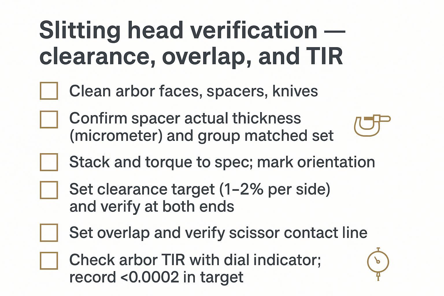
A metrology routine that actually works in production is simple and repeatable:
- Measure spacer thickness with a calibrated micrometer.
- Measure parallelism by checking multiple points (don’t trust a single reading).
- Check arbor TIR with a dial indicator at the functional surfaces you care about.
- Record results by set ID so the data survives the shift change.
If you don’t record it, you can’t separate “tooling variability” from “setup variability.”
Changeover and torque control
Width issues that appear after a “routine” changeover are often torque and cleanliness problems.
Control them with discipline:
- Clean contact faces (arbor, spacers, knives) before stacking.
- Torque to a documented target and use the same sequence each time.
- Mark orientation if your operation reuses stacks.
- Recheck TIR after final torque—torque can move the stack.
Troubleshooting quality
Burrs and ragged edges
If burrs increase or edges turn ragged, troubleshoot in this order:
- Verify clearance and overlap (don’t adjust blindly).
- Check knife sharpness and edge condition. A dull edge widens the effective shear zone and raises burr risk.
- Confirm stack seating (debris, nicks, rough faces).
- Check runout/TIR (knife and arbor).
For practical maintenance steps that keep edge geometry stable longer, see mantenere affilata la lama della taglierina.
Width drift and camber
Width drift usually comes from one of three buckets:
- Stack-up drift: spacers were swapped, mixed, or not matched by actual thickness.
- Mechanical drift: runout increased, bearings warmed, or torque/seat changed.
- Process drift: tension changes or material variability pulls the web differently.
Camber complaints often show up when width is “in spec” but the strip doesn’t track. That’s a reminder: width accuracy and web control are linked. A stable stack makes tension control easier; unstable stack makes every other variable more sensitive.
Vibration and chatter
Chatter is rarely fixed by “turning a knob.” It’s usually a rigidity problem:
- too many thin spacers in one pocket
- poor surface condition on contact faces
- runout pushing the system into periodic loading
- insufficient torque or inconsistent torque
When chatter appears, stop treating it as a speed problem and start treating it as a stack stiffness and metrology problem.
Case study: reducing burrs and width drift by stabilizing the stack
In one rotary shear slitting application, a processor was running CR steel coil (SPCC equivalent) A 0.50 mm thickness and 1250 mm coil width, with 8 strands A 120 m/min. The targets were ±0.05 mm slit width tolerance and burr <0.03 mm.
Here’s a before/after snapshot from that run:
| Metrico | Prima | Dopo |
|---|---|---|
| Burr height | 0.045–0.060 mm | 0.018–0.025 mm |
| Width deviation | ±0.12 mm | ±0.04 mm |
| Burr-related stoppages | 2–3/week | <1/week |
| Average setup time | 48 min | 34 min |
What changed: they treated the stack like a precision assembly—matched spacers by actual measured thickness, cleaned contact faces, used a documented torque + sequence, and verified/corrected arbor and knife TIR with a dial indicator.
The takeaway isn’t that one number fixes everything—it’s that stack discipline + verification makes your clearance/overlap window repeatable, which is what stabilizes burr and width in real production.
Conclusione
- Key metrics recap: spacer ±0.0002–0.0005 in; TIR <0.0002 in; Ra 8–16 µin
Those three numbers are a practical starting point because they map directly to what you can control: spacing, true running, and how reliably the stack seats.
Importante: Treat these as starting targets, not universal specs. The practical window shifts with material grade and thickness, coating/hardness, knife geometry, line tension, speed, and OEM head design. The way to make them “real” in your plant is to document the setup that worked (knife + spacer set ID, torque sequence, measured TIR, and material SKU) and then iterate based on your own measurements.
- Targets: clearance 1–2%/side; burr <0.0005–0.001 in; repeatability ±0.002–0.005 in
If you hit those targets consistently, you usually see the business outcome that matters: less scrap, fewer “mystery” width issues, and faster changeovers.
If you want a second set of eyes on your tolerance stack and verification routine, MAXTOR METAL can quote coltelli + spacer sets and provide matched-set measurement documentation and import traceability so your team can audit performance by set ID.
For a broader TCO lens on keeping edge quality stable longer, see MAXTOR METAL’s guidance on how to extend slitter blade life (TCO view).
This article is written as a best-practices reference for production slitting teams. Where numeric targets are provided, they are intended as practical starting points that should be validated against your material, product requirements, and OEM guidance.
At MAXTOR METAL, we support slitting operations with custom, precision-ground knives and spacers, and we can provide:
- Matched-set measurement records (actual spacer thickness data by set)
- Lot traceability that links set ID, inspection records, and shipping documents
- Quality-control documentation aligned to incoming material checks and in-process inspections
If you’d like an engineering review of your stack plan, share your slit pattern, material specs, and current metrology readings (thickness data + TIR), and we can help you identify whether the dominant driver is stack-up, runout, or process stability.
FAQ
What do slitter spacers actually do in shear slitting?
They set the distance between knives, which directly sets the slit pattern and lane widths. In stacked systems they also act as structural members: how well they seat and match affects rigidity, which affects clearance stability and burr control.
How does spacer tolerance stack-up cause slit width drift?
Each spacer has a small thickness error from nominal. In a stack, the lane position is the sum of all spacer thicknesses up to that knife, so those small errors add into a measurable width deviation—especially when there are many spacers.
What thickness tolerance should I specify for slitter spacers?
It depends on your repeatability target and how many parts are in the stack. A common practical range for precision work is ±0.0002–0.0005 in, then tighten further or use matched sets when you need tighter width repeatability.
Why does arbor runout (TIR) show up as burrs?
Runout changes effective clearance and overlap as the knives rotate. That means the cut alternates between “too tight” and “too loose” conditions in one revolution, which shows up as intermittent burr and inconsistent edge finish.
What are good clearance and overlap targets to reduce burrs?
A useful starting target is clearance of about 1–2% per side for many shear slitting jobs, then fine-tune based on material and thickness. Overlap should be set so the knives meet cleanly without forcing the male knife to lead into unsupported material.
How do I check slitter spacer thickness and parallelism on the shop floor?
Use a calibrated micrometer for thickness and take multiple readings around the spacer to confirm it isn’t wedge-shaped. If you need higher confidence, add a surface plate check and record measurements by set ID.
Should I buy spacers and knives as matched sets?
If you care about repeatable width and fast changeovers, matched sets usually reduce risk because the supplier measures and groups actual thickness values and provides documentation. That makes troubleshooting faster and reduces “mix-and-match” stack-up surprises.
What’s the fastest way to reduce burrs without changing the whole setup?
Start with verification: confirm clearance and overlap haven’t drifted, then inspect knife edges and stack seating. If the stack is clean, torqued consistently, and TIR is controlled, many burr problems disappear without major process changes.