

In continuous metal coil processing, achieving a clean, square, and burr-free edge is the primary benchmark of a well-calibrated slitting line. Behind every high-yield slitting run are two critical geometric parameters governing shear-cut quality: horizontal side clearance and vertical rotary knife overlap. While horizontal clearance dictates the stress concentration across the strip width, vertical knife overlap determines the exact depth of blade penetration required to transition the metal cleanly from plastic deformation into controlled fracture.
The operational significance of rotary knife overlap cannot be overstated. Setting the correct vertical overlap minimizes burr height, preserves cut edge geometry, and dramatically extends blade working life. Conversely, incorrect overlap settings drive edge tearing, excessive burr generation, premature blade chipping, scrap generation, and costly line downtime.
For coil slitting line supervisors, process engineers, and plant managers, mastering overlap calibration is essential for maintaining strict edge tolerances. Equipment operators can eliminate guesswork, protect high-value coil stock, and achieve consistent, repeatable edge quality across diverse material grades by deploying dynamic, material-aware adjustment protocols alongside precision-ground tooling.
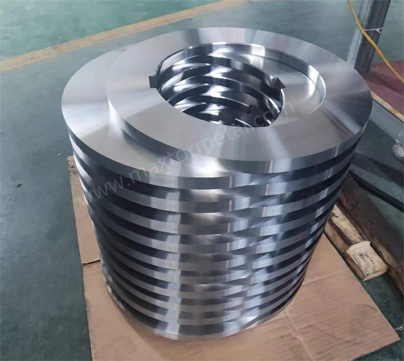
Maxtor Metal designs and manufactures rotary slitting knives and arbor spacers to the dimensional tolerances this guide describes — including OD concentricity, face flatness, and hardness consistency across a full knife set — so that overlap settings made on paper translate directly to stable cut behavior on the line.
What this guide covers
A technical and setup reference for vertical rotary knife overlap in coil slitting: why penetration depth controls fracture initiation, how overlap interacts with horizontal clearance to determine burnish/break ratio, material-specific starting windows for carbon steel, AHSS, aluminum, and stainless, and how automated arbor positioning systems maintain — or lose — a stable overlap setting across a production run.
対象読者
Process engineers setting or auditing overlap for a new material grade or gauge; maintenance leads troubleshooting edge burr and knife wear linked to penetration error; equipment operators calibrating automated arbor positioning systems after a regrind; technical procurement evaluating knife dimensional specifications that affect overlap stability.
稼働中のラインでの活用方法: start with the material-specific overlap table as your baseline → verify arbor alignment and knife OD before adjusting penetration → make one change at a time and run a short verification strip → log the result against the burr acceptance band before moving to production speed.
追跡すべき重要指標
バリの高さ as % of strip thickness at steady-state production speed · Burnish/break ratio on the cut face (target ~1:2 to 1:3 for standard carbon steel) · Knife OD after each regrind (to recalculate required arbor height correction) · Edge condition at 30–50× after changeover and after speed ramp
主なポイント: Overlap drift is almost always a dimensional problem — knife OD change after regrind, spacer wear, or arbor flex — not a control system failure. Fix the dimension, not the dial.
The Science of Rotary Knife Overlap

Rotary knife overlap (frequently termed penetration or vertical entry) is defined as the vertical distance that the outer periphery of the upper circular slitting blade extends below the top tangent line of the lower circular slitting blade. It represents the physical vertical engagement between opposing knife edges on the slitting arbor.
It is vital to distinguish vertical overlap from horizontal side clearance:
- Vertical Overlap: Controls the depth of initial knife entry into the strip and influences the point along the cut line where internal tensile stress exceeds the material’s ultimate shear strength.
- Horizontal Side Clearance: Refers to the lateral gap between the cutting faces of the upper and lower blades, which directs the angle and propagation path of the shear fracture.
重要なポイント: Vertical overlap controls how deeply the rotary knives penetrate the metal strip before fracture occurs, while horizontal side clearance directs the angle of propagation. Both parameters must work in tandem to establish a clean edge.
The fundamental governing principle for setting vertical overlap is the minimum overlap for a stable cut rule. The optimal vertical overlap is the smallest penetration depth that produces a complete, continuous fracture across the full length and width of the coil without leaving uncut strands or slivers.
As a baseline reference across standard light-to-medium gauge carbon steels, vertical overlap typically falls within a window equal to 5% to 15% of the strip thickness. However, this baseline must be dynamically adjusted depending on material ductiled tensile strength, strip gauge, and arbor rigidity.
The Consequences of Incorrect Overlap
Deviating from the optimal overlap window compromises edge geometry and accelerates mechanical wear on slitting arbors and tooling.
1. Under-Overlap (Insufficient Penetration)
When the upper knife does not penetrate deeply enough below the lower knife tangent plane:
- Incomplete Separation: The metal strip fails to fracture completely, leading to uncut sections or persistent web strands that jam downstream coiling equipment.
- Ragged and Torn Edges: Instead of a clean fracture, the metal undergoes excessive tensile stretching, resulting in torn, jagged edge profiles with heavy hanging burrs.
- Slivers and Debris: Incomplete shearing creates fine metallic slivers and wire-like burrs that contaminate strip surfaces and damage tension stand rolls.
For a complete root-cause diagnostic framework — covering clearance, knife condition, alignment, and tension as the full variable set — see the Slitting Burr Reduction: Root-Cause Matrix, Setup Windows & Inspection Protocol.
2. Over-Overlap (Excessive Penetration)
When the upper knife penetrates too deeply into the lower knife plane:
- Increased Friction and Heat: Excessive blade engagement creates severe friction along the knife side faces, causing thermal expansion, localized overheating, and loss of edge hardness.
- Edge Galling and Chipping: Heavy vertical loading forces metal against the blade side walls, causing material pickup (galling) on aluminum or stainless coils and micro-chipping along the knife cutting edge.
- Metal Dust Formation: Deep penetration grinds the sheared edge, creating fine iron powder or metal dust that accumulates in arbor bearings and optical line sensors.
- Accelerated Tool Wear: Excessive overlap forces the knives to perform unnecessary sliding work, shortening regrind intervals by up to 50%.
Coordinating Overlap with Horizontal Clearance
Vertical overlap cannot be adjusted in isolation. Shear cutting relies on a balanced two-stage fracture mechanism:
- Plastic Deformation (Burnish/Shear Band): The knives penetrate the upper and lower surfaces of the strip, creating a smooth, shiny burnished band that typically accounts for the upper 20% to 35% of strip thickness.
- Brittle Fracture (Break Band): As vertical penetration reaches the critical strain threshold, cracks initiate from opposing knife tips and meet in the middle, creating a matte fracture zone that covers the remaining 65% to 80% of strip thickness.
To maintain a clean edge profile (with a burnish-to-fracture ratio of roughly 1:2 or 1:3), vertical overlap and horizontal clearance must be balanced simultaneously. If horizontal clearance is widened for a harder material, vertical overlap must often be reduced slightly to prevent excessive bending moments across the shear zone.
That burnish-to-fracture split is not a universal constant—it shifts sharply with material behavior, and reading it correctly is one of the fastest ways to judge whether a cut is running properly. In Advanced High-Strength Steel (AHSS), high yield strength drives crack initiation almost the moment the blade engages, so the burnish zone can collapse to under 10% of strip thickness and the edge is dominated by a brittle break band. Mild carbon steel sits in the middle, producing the familiar burnish band of roughly 20% to 35%. Soft aluminum alloys, with their high elongation and ductility, resist fracture far longer, yielding a noticeably thicker burnish band and a smaller fracture zone. This matters for edge specifications: a thick, shiny burnish zone points to excessive plastic deformation (deep penetration, or too-tight clearance), while a nearly absent burnish band suggests the material is fracturing almost instantly—expected in AHSS, but a red flag if it appears on a ductile grade.
This balance is echoed in published tooling practice. The setup method described in U.S. Patent US4680851A, for example, states that knife clearance should approximate 10% of strip gauge for hard temper そして 5% for soft temper—a direct illustration of how clearance must track material condition rather than follow a single fixed figure. Industry process references such as IspatGuru similarly note that knife horizontal clearance and vertical overlap are both critical to slit quality, warning that a large horizontal clearance can cause excessive edge roll-over and burr, while an excessively tight clearance risks premature knife wear or damage.
Furthermore, knife calibration is not a one-time setup. Both vertical overlap and horizontal clearance must be re-calculated and verified whenever:
- Knives are reground or replaced (accounting for blade outer diameter reduction).
- Stripper rings or arbor spacers are changed.
- The processing line shifts to a new coil thickness, temper, or material grade.
Material-Specific Overlap Guidance
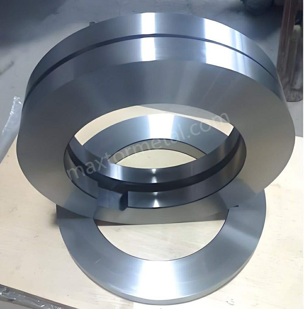
A common pitfall in coil slitting operations is applying a fixed percentage rule across all metal grades. Material behavior during shear cutting varies dramatically based on yield strength, tensile strength, strain hardening exponent, ductility, and surface coating.
Advanced materials demand tighter operational windows:
- Advanced High-Strength Steels (AHSS): High yield strength means crack initiation occurs almost immediately upon blade entry. Excessive overlap causes severe shock loading and knife edge breakdown.
- Coating-Sensitive Aluminum: Soft, ductile aluminum alloys possess high elongation properties and stickiness, making them prone to edge rollover and side-face galling if vertical entry is even slightly excessive.
Recommended Overlap Ranges by Material
The table below outlines baseline vertical overlap parameters, horizontal clearances, and characteristic edge outcomes across primary industrial coil alloys:
| Material Family | Typical Yield Strength | Recommended Vertical Overlap (% of Strip Thickness) | Recommended Horizontal Clearance (% per side) | Edge Quality & Process Behavior |
|---|---|---|---|---|
| Mild Carbon Steel (CR4, DD11, A36) | 180 – 350 MPa | 10% – 15% (Light gauge)5% – 10% (Heavy gauge) | 8% – 10% | Broad processing window; smooth shear band; low sensitivity to minor setting drift. |
| Advanced High-Strength Steel (DP600, DP1000, TRIP) | 600 – 1200+ MPa | 3% – 8% | 12% – 18% | Extremely narrow window; brittle fracture occurs rapidly; requires reduced overlap to prevent blade micro-chipping. |
| Aluminum Alloys (3000, 5000, 6000 Series) | 100 – 300 MPa | 5% – 10% | 5% – 7% | High risk of edge burrs and pickup; minimal overlap required; demands highly polished knife faces. |
| Stainless Steel (304, 316, 430 Series) | 250 – 600 MPa | 8% – 12% | 10% – 15% | High work-hardening rate; requires precise penetration to snap the edge cleanly without dragging or work-hardening burrs. |
A general rule of thumb applies to strip thickness: thinner, ductile metals require a higher percentage of vertical overlap to initiate crack propagation, whereas thicker, high-strength metals require significantly less vertical overlap because the material fractures under lighter entry depths.
These process margins are framed by internationally recognized product standards. Slit width tolerances and edge classifications are governed by specifications such as ASTM A568/A568M そして ASTM A109/A109M (which define edge conditions including No. 3 slit edge), while ASTM A480/A480M covers edge conditions for stainless steel and ISO 9445-2 sets dimensional and form tolerances for slit cold-rolled stainless strip. Note that the term “burr” is formally defined in ASTM A623 as metal displaced beyond the surface plane by slitting or shearing. Clearance and overlap values themselves are not fixed by a single mandatory standard; they remain process-setting recommendations that must be tuned within the dimensional windows those standards define.
Precision Tooling for Stable Overlap
Holding vertical overlap tolerances across a multi-knife arbor—sometimes carrying 20 to 50 individual slitting heads—requires sub-micron mechanical accuracy. If individual rotary knives vary in outer diameter, or if spacers suffer from axial thickness variation, vertical overlap will wobble across the arbor width. A variation of just 0.01 mm in knife radius translates directly to a 0.01 mm error in vertical penetration.
To eliminate overlap drift across the arbor:
- Rotary slitting knives must be manufactured from high-purity alloy steels refined through Electroslag Remelting (ESR), such as AISI D2 (1.2379), H13 (1.2344), High-Speed Steel (M2/1.3343), or Powder Metallurgy (PM) steels. ESR processing eliminates primary eutectic carbide segregation (M₇C₃ and VC monocarbides), ensuring uniform toughness and edge wear resistance.
- Outer diameters and bore concentricity must be precision-ground to within ±0.001 mm tolerances.
- Precision arbor spacers must maintain strict parallelism to prevent cumulative axial runout and angular deflection under shear load.
For spacer tolerance specifications, face flatness targets, and rubber ring compression standards that directly affect axial runout and overlap stability, see the 精密スリッティングスペーサーおよびゴムリングガイド.
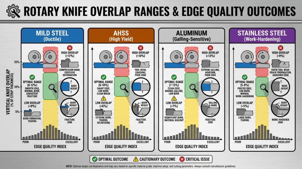
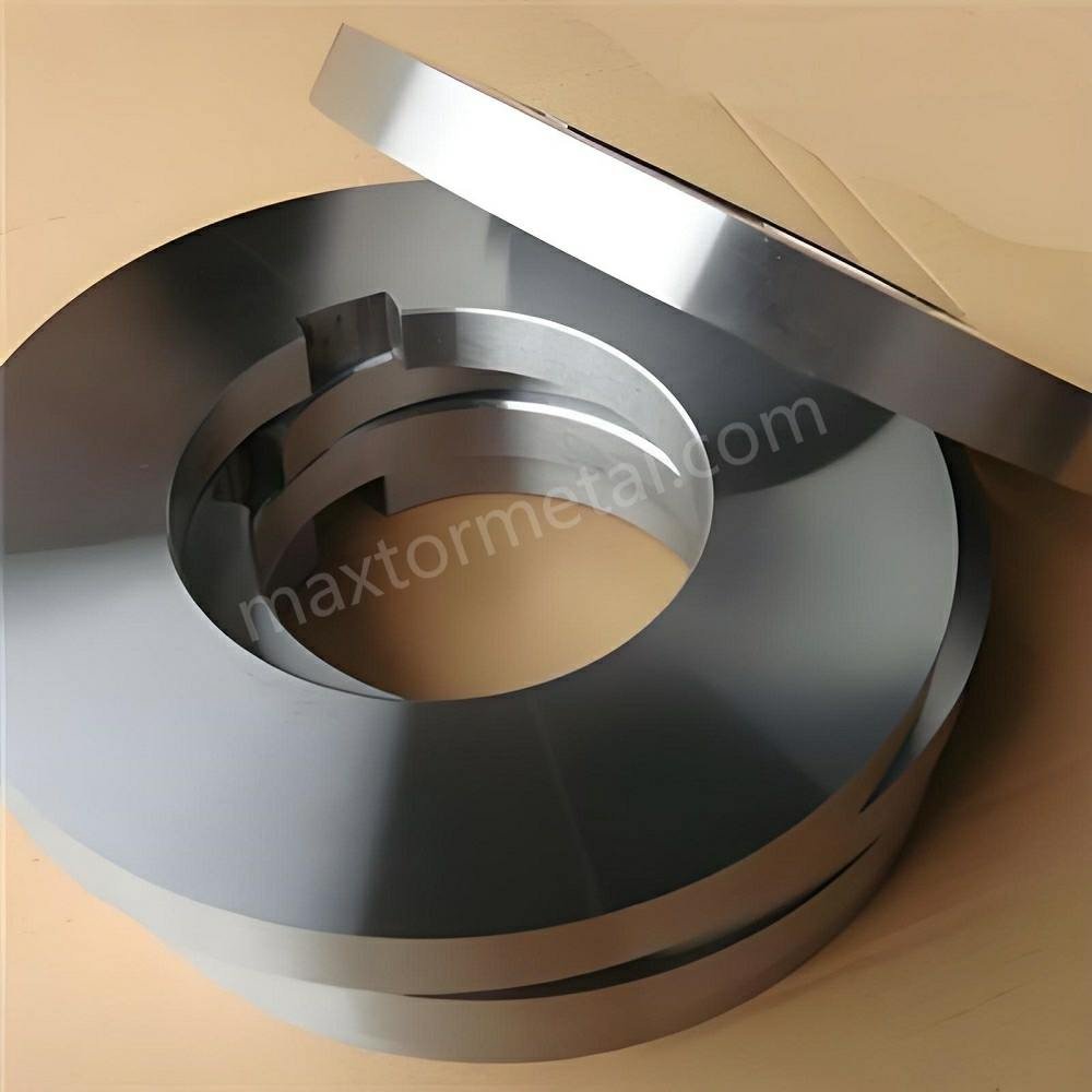
High-precision tooling solutions manufactured by Maxtor Metal, including custom-ground rotary slitting knives and hardened spacers, ensure uniform vertical overlap settings across every cut pocket. Their material selection expertise and strict thermal treatment controls help extend blade working life, maintain consistent edge burr standards, and minimize planned line stops.
Maxtor Metal’s approach to overlap stability rests on four levers that buyers can specify and verify during procurement:
- Material grade matched to the cut, not the catalog. Blade steel is selected against the target coil—carbon steel, AHSS, aluminum, or stainless—so that hardness and wear resistance suit the actual shear load rather than a generic default.
- Controlled heat treatment for uniform hardness. Consistent austenitizing, quenching, and tempering cycles reduce soft spots and patchy hardness that would otherwise make one knife wear faster than its neighbors on the same arbor.
- Precision grinding of OD, bore, and faces. Holding outer diameter, bore concentricity, and side-face flatness to tight tolerances keeps every knife in a multi-head arbor contributing the same effective penetration.
- Dimensional verification as a deliverable. Because overlap drift is ultimately caused by dimensional variation, inspection of critical dimensions before shipment lets the customer confirm that a new knife set will interface with their existing spacers and arbors without introducing overlap error.
This is the practical link between tooling quality and edge quality: because a variation of just 0.01 mm in knife radius becomes a 0.01 mm error in vertical penetration, controlling knife and spacer dimensions upstream is what allows the downstream overlap setting to remain stable.
Dynamic Overlap Adjustment in Modern Slitting Lines
Traditional slitting lines relied on manual handwheel adjustments and mechanical feeler gauges to set upper arbor heights. On modern, high-speed automated slitting lines, manual adjustments have been replaced by motorized upper arbor actuators integrated with digital recipe controls.
Automated upper arbor positioning systems dynamically reposition the upper slitting arbor relative to the fixed lower arbor based on pre-programmed material recipes. Key features of dynamic overlap control include:
- Closed-Loop Linear Encoder Feedback: Optical or magnetic encoders continuously monitor the vertical position of the arbor bearing blocks with positioning accuracy down to 0.002 mm.
- HMI Recipe Control: Equipment operators select the material grade, thickness, coil width, and knife outer diameter on the Human-Machine Interface (HMI). The control system automatically calculates and sets the required vertical penetration.
- たわみ補正: Advanced controls automatically increase vertical penetration slightly toward the center of wide arbors to offset mechanical arbor flexing under heavy shear loads.
プロのヒント: Always log reground knife outer diameters into your HMI control system. Failing to update the blade radius parameter after regrinding will cause automated positioning systems to under-penetrate the coil, resulting in severe edge burrs.
A practical note on tooling compatibility with automated systems: closed-loop positioning accuracy is only as good as the dimensional consistency of the knives and spacers it is positioning. If knife OD varies across a set, or if spacer face thickness is not held to a tight tolerance, the encoder will report the commanded position accurately — but the actual penetration at each cut pocket will still drift. Maxtor Metal‘s dimensional inspection protocol includes OD verification of every knife in a set and face parallelism checks on spacers before shipment, so that the physical stack matches the recipe input your HMI is working from.
Setup Best Practices for Consistent Edge Quality
To achieve consistent, burr-free edge quality run after run, slitting line crews should adhere to a structured setup protocol:
- Establish the Baseline Minimal Overlap: Begin setup with the conservative minimum overlap recommended for the material gauge. Increase penetration only until a complete, clean shear is achieved across all strip mults. In practice, “complete, continuous fracture” is a judgment you make from several signals together, not from the dial alone:
- No uncut strands. The most immediate check: run a short length and confirm the strip has fully separated across every mult, with no web strands or connected slivers bridging the cut. Even one surviving strand means penetration is still short of the minimum.
- Break-band meets mid-thickness. Examine the cut face: a correct cut shows opposing crack fronts from the top and bottom meeting near the strip’s mid-plane. Cracks that stall and leave a rough ridge low on the edge point to under-penetration.
- Confirm with a test strip. For a fast physical check, feed a thin test strip or use a feeler gauge to verify the knives are genuinely overlapping, since the commanded reading and real blade engagement diverge as knife OD shrinks.
- Watch the burnish-to-break ratio. A burnish band well above roughly 35% of thickness signals you’ve already pushed past the minimum; a band that stays thick after increasing penetration means the extra overlap isn’t translating into fracture.
- Verify Arbor Alignment and Parallelism: Use dial indicators to verify that the upper and lower arbors remain perfectly parallel under clamping load. Angular misalignment causes excessive overlap on one side of the line and under-overlap on the other. For a structured TIR verification procedure — covering dial indicator setup, ISO fit class selection, and blue-check acceptance protocol — see the OEM Slitter Knife Blueprint: Spindle Fit Audit, ISO Tolerances & TIR Gates.
- Recheck Settings After Every Changeover: Never assume a previous setup applies to a new master coil. Even minor variations in coil thickness (e.g., from 1.0 mm to 1.15 mm) or yield strength require re-evaluating overlap and clearance settings.
- Inspect Stripper Rings and Arbor Bearings: Ensure shore hardness and outer diameter of rubber stripper rings are matched to the knife setup. Worn arbor support bearings permit arbor movement during acceleration, causing vertical overlap to drift during high-speed running.
- Track Edge Quality Trends: Regularly measure burr height using optical comparators or micrometer burr gauges. A sudden increase in burr height indicates either knife edge dulling or vertical overlap shift caused by thermal expansion.
Field Notes: A First-Hand Troubleshooting Sequence
Drawing on 10 years of coil slitting troubleshooting across carbon steel, AHSS, stainless, and aluminum processing lines, ジェリー・チュウ, Technical Support Specialist at Maxtor Metal, offers the following field-tested diagnostic sequence. When an operator reports a sudden change in edge quality, the fastest path to root cause is to work through these variables in order — rather than reaching immediately for the overlap handwheel:
- Separate the symptom from the cause. A burr that appears only on one side of the strip usually points to arbor misalignment or unequal spacer stacking, not to a global overlap error. A burr that appears on every mult points toward a shift in the shared setup parameter.
- Check knife condition before geometry. A dull or micro-chipped edge mimics an under-overlap condition by tearing rather than shearing the metal. Confirm the cutting edge is sound before adjusting penetration, otherwise you risk compensating for a worn blade by over-driving the overlap.
- Verify the actual overlap, not the dial reading. Encoders and handwheels report commanded position, not true blade engagement. After every regrind, confirm the real penetration with a feeler gauge or a thin test strip, because the reading and reality diverge as knife OD shrinks.
- Look at the dust and slivers, not just the edge. Metal dust and fine iron powder accumulating around arbor bearings or on line sensors is a reliable sign of over-penetration — the knives are grinding the sheared edge rather than fracturing it cleanly. Metallic slivers or wire-like burrs trailing from the strip edge point in the opposite direction: insufficient penetration has left the fracture incomplete. The by-product tells you which direction the setting has drifted before the edge measurement does.
- Re-baseline after any material change. Because each alloy, temper, and gauge combination shifts the crack-initiation threshold, the overlap that produced a clean edge on one coil may be wrong for the next. Treat the last good setup as a starting hypothesis, not a guarantee.
The Business Impact of Optimized Overlap
Controlling rotary knife overlap is not merely a technical exercise—it directly drives key performance indicators (KPIs) and operational profitability for steel service centers and metal fabricators.
The figures below reflect commonly observed shop-floor outcomes, separated by primary driver: overlap calibration alone (applicable to any line with manual or automated setup), and automated positioning systems (applicable only to lines with motorized arbor control and HMI recipe management). Improvements from both drivers compound when implemented together.
From overlap calibration discipline (manual or automated lines)
- Up to 25% Reduction in Scrap: Eliminating edge slivers, heavy burrs, and off-spec slit widths prevents entire coil mults from being rejected at customer stamping plants.
- Extended Tooling Life: Avoiding over-penetration reduces friction and thermal stress, allowing high-quality slitting blades to achieve up to 40% more tonnage between regrinds.
From automated arbor positioning systems (motorized lines with recipe control)
- Shorter Changeover Times: Automated, recipe-driven overlap positioning reduces setup times from 30 minutes to under 5 minutes per coil changeover.
- Higher First-Pass Yield: Precise overlap eliminates trial-and-error test cuts, allowing lines to ramp directly to full operating speeds (up to 300 m/min) with total edge confidence.
If you’re evaluating whether a knife material upgrade can extend regrind intervals and improve overlap stability, the ロータリー式スリッターナイフの投資対効果(ROI)ガイド provides a cost-per-ton model for PM-HSS vs tool steel across AHSS, stainless, and aluminum.
In a comprehensive total cost of ownership (TCO) model, reduced scrap rates, lower maintenance downtime, and extended tooling life work together to lower the total tooling cost per processed ton of metal coil.
よくある質問(FAQ)
1. What is the difference between knife overlap and horizontal clearance in slitting?
Vertical knife overlap (or penetration) is the vertical depth that the upper circular knife extends past the lower knife’s top edge. Horizontal clearance is the sideways gap between the cutting faces of the upper and lower knives. Overlap controls the depth of initial blade entry, while horizontal clearance determines the angle of the fracture line through the metal.
2. How do I calculate the correct rotary knife overlap for steel slitting?
For standard carbon steels, a starting baseline for vertical overlap is 5% to 15% of the strip thickness. For thin gauges (under 1.0 mm), use 10% to 15% of strip thickness; for thicker gauges (over 3.0 mm), reduce overlap to 3% to 8%. Consistent with the minimum overlap for a stable cut rule defined in the Science section above, always use the smallest vertical overlap that still delivers a complete, continuous fracture across the full strip width — no uncut strands or slivers left behind.
3. What causes heavy burrs on the edge of a slit metal coil?
Heavy burrs are typically caused by either insufficient vertical overlap (which tears the metal rather than shearing it cleanly), excessive horizontal clearance、 または dull knife cutting edges. If vertical penetration is too shallow, crack propagation fails to meet in the middle, leaving a raised metal ridge along the bottom edge.
4. Why does Advanced High-Strength Steel (AHSS) require less overlap than mild steel?
AHSS possesses high yield and tensile strength, meaning internal stress reaches the ultimate fracture threshold almost immediately upon blade entry. Applying heavy overlap to AHSS causes excessive shock loads, edge chipping on the blades, and severe burr formation. AHSS requires small vertical overlap combined with wider horizontal clearance.
5. How does knife regrinding affect vertical overlap settings?
Regrinding reduces the outer diameter (OD) of a rotary slitting knife. If the upper arbor height is not adjusted downward to compensate for the smaller knife radius, the actual vertical penetration into the strip will be less than expected. Equipment operators must enter the exact post-regrind knife diameter into their line setup software or adjust arbor position manually to restore proper overlap.
6. Can incorrect overlap cause slitting knives to chip or break?
Yes. Setting excessive vertical overlap forces the side faces of opposing upper and lower knives to rub against each other or squeeze hard against the metal strip. This creates high axial loads and thermal stress, leading to galling, edge micro-chipping, or catastrophic blade fracturing—especially when processing hard alloys or stainless steel.
7. Does slitting line speed change the required knife overlap?
Yes—line speed indirectly affects overlap behavior. As speed increases, so does the heat generated by friction at the shear zone. That thermal expansion changes the effective relationship between the upper and lower arbors, so a setting that yields a clean edge at low speed can drift toward under- or over-penetration at high speed. This is why overlap should be verified at, or close to, the actual production speed rather than only during a slow jog or thread-up. Lines equipped with deflection and thermal compensation can hold overlap more consistently across a speed ramp, but manual lines should recheck edge quality after reaching steady-state operating speed.
結論
Rotary knife overlap is a foundational variable in precision coil slitting operations. Far from a static setting, vertical overlap is a dynamic parameter that directly influences cut edge burr height, shear band geometry, blade wear rates, and overall production yield.
By shifting from manual rule-of-thumb setups to material-aware, data-driven overlap calibration—and pairing automated arbor positioning with precision-ground slitting tooling—coil processors can consistently eliminate edge burrs and lower operating costs.
Upgrading your slitting line performance begins with tooling dimensioned to match your overlap targets — not generic catalog stock. Maxtor Metal‘s technical team can review your current knife geometry, regrind history, and arbor configuration, then recommend a knife steel grade, coating, and dimensional specification that holds your overlap window across a full production run. Contact us to discuss custom-ground rotary slitting knives, precision arbor spacers, and a dimensional inspection package tailored to your line configuration and material mix.
References and Standards
- ASTM A568/A568M – Standard Specification for Steel, Sheet, Carbon, Structural, and High-Strength, Low-Alloy, Hot-Rolled and Cold-Rolled, General Requirements for (slit width tolerances and edge conditions).
- ASTM A109/A109M – Standard Specification for Steel, Strip, Carbon (0.25 Maximum Percent), Cold-Rolled (edge numbering, including No. 3 slit edge).
- ASTM A480/A480M – Standard Specification for General Requirements for Flat-Rolled Stainless and Heat-Resisting Steel Plate, Sheet, and Strip (stainless edge conditions).
- ASTM A623 – Standard Specification for Tin Mill Products, General Requirements (formal definition of burr).
- ISO 9445-2 – Continuously cold-rolled stainless steel – Tolerances on dimensions and form – Part 2: Wide strip and plate/sheet, including slit cold-rolled wide strip below 600 mm width.
- US4680851A – “Method of setting up rotary slitter tooling” (U.S. patent describing clearance selection as a function of strip gauge and temper).
- IspatGuru – “Flattening, Levelling, Slitting, and Shearing of Coiled Flat Steel Product” (industry process reference covering knife horizontal clearance and vertical overlap).
The quantitative process ranges presented throughout this guide are intended as engineering starting points. Final overlap and clearance values should always be validated against the applicable product standard and confirmed on your specific slitting line configuration.
著者について
Jerry Chu is Technical Support Specialist at Maxtor Metal, with 10 years of field experience in coil slitting and precision cutting applications across carbon steel, AHSS, stainless, and aluminum processing lines.
His technical focus for this guide is overlap calibration and shear mechanics: understanding why a given penetration depth produces a clean fracture on one material and edge damage on another, how regrind cycles change effective overlap, and how automated arbor positioning systems can hold—or lose—a stable cut window across a production run. The material-specific overlap windows, burnish/break ratio guidance, and troubleshooting sequence in this article reflect the diagnostic approach Jerry applies in Maxtor Metal’s after-sales support engagements.
He holds the PMP (Project Management Professional) and CMRP (Certified Maintenance & Reliability Professional) certifications, supporting a structured, reliability-centered approach to tooling and process decisions.

 English
  Spanish
  Italian
  French
  Portuguese
  Russian
  German
  Arabic
  Hindi
Hindi  Vietnamese
  Indonesian
  Japanese
  Korean