

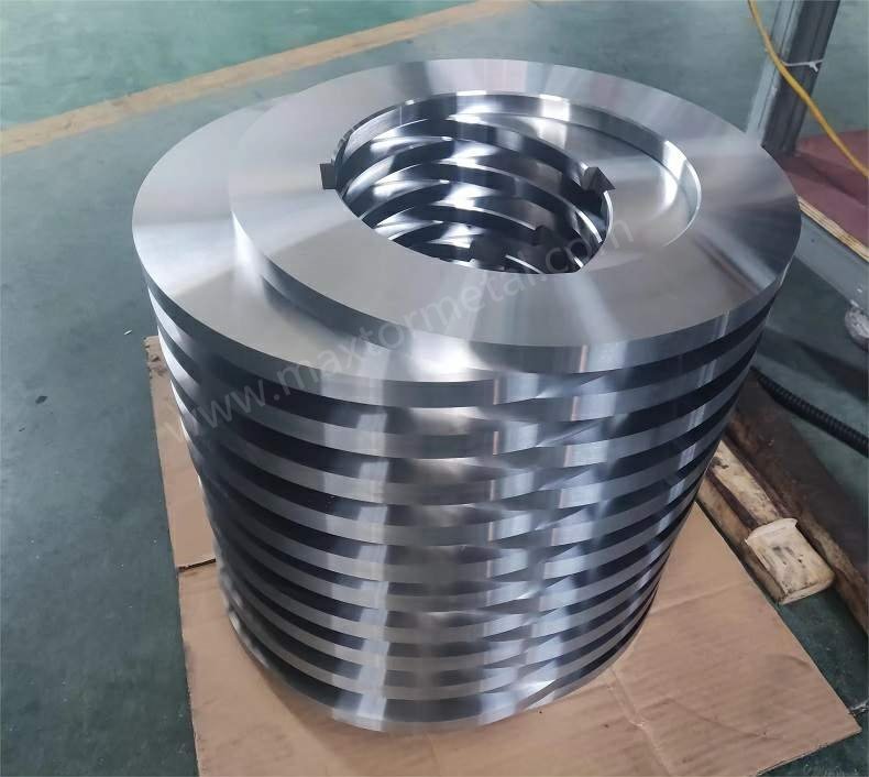
Bei der kontinuierlichen Metallbandbearbeitung ist das Erreichen einer sauberen, rechtwinkligen und gratfreien Schnittkante der wichtigste Maßstab für eine präzise eingestellte Längsteilanlage. Hinter jedem hochprofitablen Schnittverlauf stehen zwei kritische geometrische Parameter, die die Scherschnittqualität bestimmen: das horizontale Seitenspiel (Messerabstand) und die vertikale Kreismesser-Überdeckung. Während das horizontale Spiel die Spannungskonzentration über die Bandbreite steuert, bestimmt die vertikale Überdeckung die exakte Eintauchtiefe der Messer, die erforderlich ist, um den Werkstoff sauber von der plastischen Verformung in einen kontrollierten Bruch überzuführen.
Die betriebliche Bedeutung der Kreismesser-Überdeckung kann nicht hoch genug eingeschätzt werden. Die Einstellung der korrekten vertikalen Überdeckung minimiert die Grathöhe, bewahrt die Schnittkantengeometrie und verlängert die Messerstandzeit drastisch. Umgekehrt führen falsche Überdeckungseinstellungen zu Kantenausrissen, übermäßiger Gratbildung, vorzeitigen Ausbrüchen an der Schneidkante, Ausschussbildung und kostspieligen Linienstillständen.
Für Bediener von Längsteilanlagen, Prozessingenieure und Werksleiter ist die Beherrschung der Überdeckungskalibrierung unerlässlich, um strenge Schnittkantentoleranzen einzuhalten. Maschinenbediener können Mutmaßungen eliminieren, hochwertiges Bandmaterial schützen und eine konstante, reproduzierbare Kantenqualität über verschiedene Werkstoffgüten hinweg erzielen, indem sie dynamische, werkstoffspezifische Einstellprotokolle in Kombination mit präzisionsgeschliffenen Werkzeugen einsetzen.
Maxtor Metal designs and manufactures rotary slitting knives and arbor spacers to the dimensional tolerances this guide describes — including OD concentricity, face flatness, and hardness consistency across a full knife set — so that overlap settings made on paper translate directly to stable cut behavior on the line.
What this guide covers
Ein technischer Leitfaden zur Einstellung der vertikalen Kreismesser-Überdeckung beim Längsteilen von Metallbändern: Warum die Eintauchtiefe die Rissentstehung steuert, wie die Überdeckung mit dem Schnittspalt (Messerabstand) zusammenwirkt, um das Verhältnis von Glanzzone zu Bruchzone zu bestimmen, werkstoffspezifische Startfenster für Kohlenstoffstahl, AHSS, Aluminium und Edelstahl, sowie die Funktionsweise automatischer Messerwellen-Positioniersysteme zur Einhaltung — oder zum Verlust — stabiler Überdeckungseinstellungen im Produktionsverlauf.
Für wen es gedacht ist
Prozessingenieure, die die Überdeckung für eine neue Werkstoffgüte oder Banddicke einstellen oder überprüfen; Instandhaltungsleiter, die Kantengrat und Messervorschub-Verschleiß aufgrund von Eintauchtiefenfehlern beheben; Anlagenbediener, die automatische Messerwellen-Positioniersysteme nach dem Nachschleifen kalibrieren; und technischer Einkauf, der die für die Überdeckungsstabilität relevanten Messer-Maßspezifikationen bewertet.
Wie Sie es an einer laufenden Anlage anwenden: Beginnen Sie mit der werkstoffspezifischen Überdeckungstabelle als Basis → Überprüfen Sie die Messerwellenausrichtung und den Messer-Außendurchmesser (OD) vor dem Einstellen der Eintauchtiefe → Nehmen Sie jeweils nur eine Änderung vor und fahren Sie einen kurzen Prüfstreifen → Protokollieren Sie das Ergebnis gegen das Grat-Toleranzband, bevor Sie auf Produktionsgeschwindigkeit hochfahren.
Wichtige Kennzahlen zur Überwachung
Burr height as % of strip thickness at steady-state production speed · Burnish/break ratio on the cut face (target ~1:2 to 1:3 for standard carbon steel) · Knife OD after each regrind (to recalculate required arbor height correction) · Edge condition at 30–50× after changeover and after speed ramp
Wichtigste Erkenntnis: Eine Überdeckungsabweichung ist fast immer ein dimensionales Problem – Änderung des Messer-Außendurchmessers nach dem Nachschleifen, Verschleiß der Zwischenringe oder Messerwellendurchbiegung – und kein Fehler des Steuerungssystems. Korrigieren Sie das Maß, nicht den Regler.
Die Wissenschaft der Kreismesser-Überdeckung

Rotary knife overlap (frequently termed penetration or vertical entry) is defined as the vertical distance that the outer periphery of the upper circular slitting blade extends below the top tangent line of the lower circular slitting blade. It represents the physical vertical engagement between opposing knife edges on the slitting arbor.
It is vital to distinguish vertical overlap from horizontal side clearance:
- Vertical Overlap: Controls the depth of initial knife entry into the strip and influences the point along the cut line where internal tensile stress exceeds the material’s ultimate shear strength.
- Horizontal Side Clearance: Refers to the lateral gap between the cutting faces of the upper and lower blades, which directs the angle and propagation path of the shear fracture.
Wichtigste Erkenntnis: Vertical overlap controls how deeply the rotary knives penetrate the metal strip before fracture occurs, while horizontal side clearance directs the angle of propagation. Both parameters must work in tandem to establish a clean edge.
The fundamental governing principle for setting vertical overlap is the minimum overlap for a stable cut rule. The optimal vertical overlap is the smallest penetration depth that produces a complete, continuous fracture across the full length and width of the coil without leaving uncut strands or slivers.
As a baseline reference across standard light-to-medium gauge carbon steels, vertical overlap typically falls within a window equal to 5% to 15% of the strip thickness. However, this baseline must be dynamically adjusted depending on material ductiled tensile strength, strip gauge, and arbor rigidity.
The Consequences of Incorrect Overlap
Deviating from the optimal overlap window compromises edge geometry and accelerates mechanical wear on slitting arbors and tooling.
1. Under-Overlap (Insufficient Penetration)
When the upper knife does not penetrate deeply enough below the lower knife tangent plane:
- Incomplete Separation: The metal strip fails to fracture completely, leading to uncut sections or persistent web strands that jam downstream coiling equipment.
- Ragged and Torn Edges: Instead of a clean fracture, the metal undergoes excessive tensile stretching, resulting in torn, jagged edge profiles with heavy hanging burrs.
- Slivers and Debris: Incomplete shearing creates fine metallic slivers and wire-like burrs that contaminate strip surfaces and damage tension stand rolls.
For a complete root-cause diagnostic framework — covering clearance, knife condition, alignment, and tension as the full variable set — see the Slitting Burr Reduction: Root-Cause Matrix, Setup Windows & Inspection Protocol.
2. Over-Overlap (Excessive Penetration)
When the upper knife penetrates too deeply into the lower knife plane:
- Increased Friction and Heat: Excessive blade engagement creates severe friction along the knife side faces, causing thermal expansion, localized overheating, and loss of edge hardness.
- Edge Galling and Chipping: Heavy vertical loading forces metal against the blade side walls, causing material pickup (galling) on aluminum or stainless coils and micro-chipping along the knife cutting edge.
- Metal Dust Formation: Deep penetration grinds the sheared edge, creating fine iron powder or metal dust that accumulates in arbor bearings and optical line sensors.
- Accelerated Tool Wear: Excessive overlap forces the knives to perform unnecessary sliding work, shortening regrind intervals by up to 50%.
Coordinating Overlap with Horizontal Clearance
Vertical overlap cannot be adjusted in isolation. Shear cutting relies on a balanced two-stage fracture mechanism:
- Plastic Deformation (Burnish/Shear Band): The knives penetrate the upper and lower surfaces of the strip, creating a smooth, shiny burnished band that typically accounts for the upper 20% to 35% of strip thickness.
- Brittle Fracture (Break Band): As vertical penetration reaches the critical strain threshold, cracks initiate from opposing knife tips and meet in the middle, creating a matte fracture zone that covers the remaining 65% to 80% of strip thickness.
To maintain a clean edge profile (with a burnish-to-fracture ratio of roughly 1:2 or 1:3), vertical overlap and horizontal clearance must be balanced simultaneously. If horizontal clearance is widened for a harder material, vertical overlap must often be reduced slightly to prevent excessive bending moments across the shear zone.
That burnish-to-fracture split is not a universal constant—it shifts sharply with material behavior, and reading it correctly is one of the fastest ways to judge whether a cut is running properly. In Advanced High-Strength Steel (AHSS), high yield strength drives crack initiation almost the moment the blade engages, so the burnish zone can collapse to under 10% of strip thickness and the edge is dominated by a brittle break band. Mild carbon steel sits in the middle, producing the familiar burnish band of roughly 20% to 35%. Soft aluminum alloys, with their high elongation and ductility, resist fracture far longer, yielding a noticeably thicker burnish band and a smaller fracture zone. This matters for edge specifications: a thick, shiny burnish zone points to excessive plastic deformation (deep penetration, or too-tight clearance), while a nearly absent burnish band suggests the material is fracturing almost instantly—expected in AHSS, but a red flag if it appears on a ductile grade.
This balance is echoed in published tooling practice. The setup method described in U.S. Patent US4680851A, for example, states that knife clearance should approximate 10% of strip gauge for hard temper und 5% for soft temper—a direct illustration of how clearance must track material condition rather than follow a single fixed figure. Industry process references such as IspatGuru similarly note that knife horizontal clearance and vertical overlap are both critical to slit quality, warning that a large horizontal clearance can cause excessive edge roll-over and burr, while an excessively tight clearance risks premature knife wear or damage.
Furthermore, knife calibration is not a one-time setup. Both vertical overlap and horizontal clearance must be re-calculated and verified whenever:
- Knives are reground or replaced (accounting for blade outer diameter reduction).
- Stripper rings or arbor spacers are changed.
- The processing line shifts to a new coil thickness, temper, or material grade.
Werkstoffspezifische Richtlinien zur Überdeckung
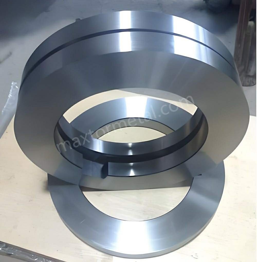
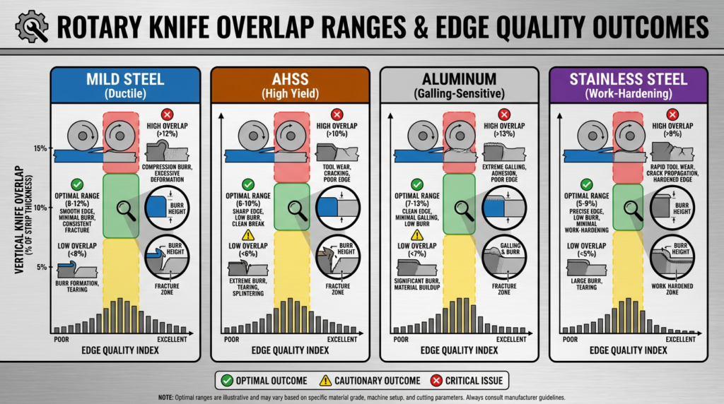
A common pitfall in coil slitting operations is applying a fixed percentage rule across all metal grades. Material behavior during shear cutting varies dramatically based on yield strength, tensile strength, strain hardening exponent, ductility, and surface coating.
Advanced materials demand tighter operational windows:
- Advanced High-Strength Steels (AHSS): High yield strength means crack initiation occurs almost immediately upon blade entry. Excessive overlap causes severe shock loading and knife edge breakdown.
- Coating-Sensitive Aluminum: Soft, ductile aluminum alloys possess high elongation properties and stickiness, making them prone to edge rollover and side-face galling if vertical entry is even slightly excessive.
Recommended Overlap Ranges by Material
The table below outlines baseline vertical overlap parameters, horizontal clearances, and characteristic edge outcomes across primary industrial coil alloys:
| Material Family | Typical Yield Strength | Recommended Vertical Overlap (% of Strip Thickness) | Recommended Horizontal Clearance (% per side) | Edge Quality & Process Behavior |
|---|---|---|---|---|
| Mild Carbon Steel (CR4, DD11, A36) | 180 – 350 MPa | 10% – 15% (Light gauge)5% – 10% (Heavy gauge) | 8% – 10% | Broad processing window; smooth shear band; low sensitivity to minor setting drift. |
| Advanced High-Strength Steel (DP600, DP1000, TRIP) | 600 – 1200+ MPa | 3% – 8% | 12% – 18% | Extremely narrow window; brittle fracture occurs rapidly; requires reduced overlap to prevent blade micro-chipping. |
| Aluminum Alloys (3000, 5000, 6000 Series) | 100 – 300 MPa | 5% – 10% | 5% – 7% | High risk of edge burrs and pickup; minimal overlap required; demands highly polished knife faces. |
| Stainless Steel (304, 316, 430 Series) | 250 – 600 MPa | 8% – 12% | 10% – 15% | High work-hardening rate; requires precise penetration to snap the edge cleanly without dragging or work-hardening burrs. |
A general rule of thumb applies to strip thickness: thinner, ductile metals require a higher percentage of vertical overlap to initiate crack propagation, whereas thicker, high-strength metals require significantly less vertical overlap because the material fractures under lighter entry depths.
These process margins are framed by internationally recognized product standards. Slit width tolerances and edge classifications are governed by specifications such as ASTM A568/A568M und ASTM A109/A109M (which define edge conditions including No. 3 slit edge), while ASTM A480/A480M covers edge conditions for stainless steel and ISO 9445-2 sets dimensional and form tolerances for slit cold-rolled stainless strip. Note that the term “burr” is formally defined in ASTM A623 as metal displaced beyond the surface plane by slitting or shearing. Clearance and overlap values themselves are not fixed by a single mandatory standard; they remain process-setting recommendations that must be tuned within the dimensional windows those standards define.
Precision Tooling for Stable Overlap
Holding vertical overlap tolerances across a multi-knife arbor—sometimes carrying 20 to 50 individual slitting heads—requires sub-micron mechanical accuracy. If individual rotary knives vary in outer diameter, or if spacers suffer from axial thickness variation, vertical overlap will wobble across the arbor width. A variation of just 0.01 mm in knife radius translates directly to a 0.01 mm error in vertical penetration.
To eliminate overlap drift across the arbor:
- Rotary slitting knives must be manufactured from high-purity alloy steels refined through Electroslag Remelting (ESR), such as AISI D2 (1.2379), H13 (1.2344), High-Speed Steel (M2/1.3343), or Powder Metallurgy (PM) steels. ESR processing eliminates primary eutectic carbide segregation (M₇C₃ and VC monocarbides), ensuring uniform toughness and edge wear resistance.
- Outer diameters and bore concentricity must be precision-ground to within ±0.001 mm tolerances.
- Precision arbor spacers must maintain strict parallelism to prevent cumulative axial runout and angular deflection under shear load.
For spacer tolerance specifications, face flatness targets, and rubber ring compression standards that directly affect axial runout and overlap stability, see the precision slitting spacers and rubber rings guide. For the stack-up arithmetic showing how knife OD variation and spacer thickness errors accumulate into width deviation across a full arbor — including TIR target bands and worst-case vs RSS models — see Rotary Slitter Axial Runout: Stack-Up Math, TIR Targets & Width Control.
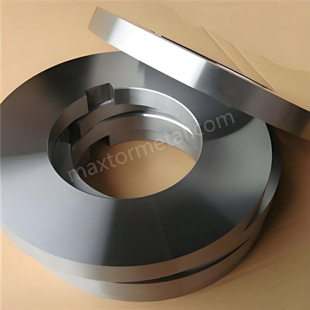
High-precision tooling solutions manufactured by Maxtor Metal, including custom-ground rotary slitting knives and hardened spacers, ensure uniform vertical overlap settings across every cut pocket. Their material selection expertise and strict thermal treatment controls help extend blade working life, maintain consistent edge burr standards, and minimize planned line stops.
Maxtor Metal’s approach to overlap stability rests on four levers that buyers can specify and verify during procurement:
- Material grade matched to the cut, not the catalog. Blade steel is selected against the target coil—carbon steel, AHSS, aluminum, or stainless—so that hardness and wear resistance suit the actual shear load rather than a generic default.
- Controlled heat treatment for uniform hardness. Consistent austenitizing, quenching, and tempering cycles reduce soft spots and patchy hardness that would otherwise make one knife wear faster than its neighbors on the same arbor.
- Precision grinding of OD, bore, and faces. Holding outer diameter, bore concentricity, and side-face flatness to tight tolerances keeps every knife in a multi-head arbor contributing the same effective penetration.
- Dimensional verification as a deliverable. Because overlap drift is ultimately caused by dimensional variation, inspection of critical dimensions before shipment lets the customer confirm that a new knife set will interface with their existing spacers and arbors without introducing overlap error.
This is the practical link between tooling quality and edge quality: because a variation of just 0.01 mm in knife radius becomes a 0.01 mm error in vertical penetration, controlling knife and spacer dimensions upstream is what allows the downstream overlap setting to remain stable.
Dynamische Überdeckungseinstellung in modernen Längsteilanlagen
Traditional slitting lines relied on manual handwheel adjustments and mechanical feeler gauges to set upper arbor heights. On modern, high-speed automated slitting lines, manual adjustments have been replaced by motorized upper arbor actuators integrated with digital recipe controls.
Automated upper arbor positioning systems dynamically reposition the upper slitting arbor relative to the fixed lower arbor based on pre-programmed material recipes. Key features of dynamic overlap control include:
- Closed-Loop Linear Encoder Feedback: Optical or magnetic encoders continuously monitor the vertical position of the arbor bearing blocks with positioning accuracy down to 0.002 mm.
- HMI Recipe Control: Equipment operators select the material grade, thickness, coil width, and knife outer diameter on the Human-Machine Interface (HMI). The control system automatically calculates and sets the required vertical penetration.
- Deflection Compensation: Advanced controls automatically increase vertical penetration slightly toward the center of wide arbors to offset mechanical arbor flexing under heavy shear loads.
Profi-Tipp: Always log reground knife outer diameters into your HMI control system. Failing to update the blade radius parameter after regrinding will cause automated positioning systems to under-penetrate the coil, resulting in severe edge burrs.
A practical note on tooling compatibility with automated systems: closed-loop positioning accuracy is only as good as the dimensional consistency of the knives and spacers it is positioning. If knife OD varies across a set, or if spacer face thickness is not held to a tight tolerance, the encoder will report the commanded position accurately — but the actual penetration at each cut pocket will still drift. Maxtor Metal‘s dimensional inspection protocol includes OD verification of every knife in a set and face parallelism checks on spacers before shipment, so that the physical stack matches the recipe input your HMI is working from.
Setup Best Practices for Consistent Edge Quality
To achieve consistent, burr-free edge quality run after run, slitting line crews should adhere to a structured setup protocol:
- Establish the Baseline Minimal Overlap: Begin setup with the conservative minimum overlap recommended for the material gauge. Increase penetration only until a complete, clean shear is achieved across all strip mults. In practice, “complete, continuous fracture” is a judgment you make from several signals together, not from the dial alone:
- No uncut strands. The most immediate check: run a short length and confirm the strip has fully separated across every mult, with no web strands or connected slivers bridging the cut. Even one surviving strand means penetration is still short of the minimum.
- Break-band meets mid-thickness. Examine the cut face: a correct cut shows opposing crack fronts from the top and bottom meeting near the strip’s mid-plane. Cracks that stall and leave a rough ridge low on the edge point to under-penetration.
- Confirm with a test strip. For a fast physical check, feed a thin test strip or use a feeler gauge to verify the knives are genuinely overlapping, since the commanded reading and real blade engagement diverge as knife OD shrinks.
- Watch the burnish-to-break ratio. A burnish band well above roughly 35% of thickness signals you’ve already pushed past the minimum; a band that stays thick after increasing penetration means the extra overlap isn’t translating into fracture.
- Verify Arbor Alignment and Parallelism: Use dial indicators to verify that the upper and lower arbors remain perfectly parallel under clamping load. Angular misalignment causes excessive overlap on one side of the line and under-overlap on the other. For a structured TIR verification procedure — covering dial indicator setup, ISO fit class selection, and blue-check acceptance protocol — see the OEM Slitter Knife Blueprint: Spindle Fit Audit, ISO Tolerances & TIR Gates.
- Recheck Settings After Every Changeover: Never assume a previous setup applies to a new master coil. Even minor variations in coil thickness (e.g., from 1.0 mm to 1.15 mm) or yield strength require re-evaluating overlap and clearance settings.
- Inspect Stripper Rings and Arbor Bearings: Ensure shore hardness and outer diameter of rubber stripper rings are matched to the knife setup. Worn arbor support bearings permit arbor movement during acceleration, causing vertical overlap to drift during high-speed running.
- Track Edge Quality Trends: Regularly measure burr height using optical comparators or micrometer burr gauges. A sudden increase in burr height indicates either knife edge dulling or vertical overlap shift caused by thermal expansion.
Field Notes: A First-Hand Troubleshooting Sequence
Drawing on 10 years of coil slitting troubleshooting across carbon steel, AHSS, stainless, and aluminum processing lines, Jerry Chu, Technical Support Specialist at Maxtor Metal, offers the following field-tested diagnostic sequence. When an operator reports a sudden change in edge quality, the fastest path to root cause is to work through these variables in order — rather than reaching immediately for the overlap handwheel:
- Separate the symptom from the cause. A burr that appears only on one side of the strip usually points to arbor misalignment or unequal spacer stacking, not to a global overlap error. A burr that appears on every mult points toward a shift in the shared setup parameter.
- Check knife condition before geometry. A dull or micro-chipped edge mimics an under-overlap condition by tearing rather than shearing the metal. Confirm the cutting edge is sound before adjusting penetration, otherwise you risk compensating for a worn blade by over-driving the overlap.
- Verify the actual overlap, not the dial reading. Encoders and handwheels report commanded position, not true blade engagement. After every regrind, confirm the real penetration with a feeler gauge or a thin test strip, because the reading and reality diverge as knife OD shrinks.
- Look at the dust and slivers, not just the edge. Metal dust and fine iron powder accumulating around arbor bearings or on line sensors is a reliable sign of over-penetration — the knives are grinding the sheared edge rather than fracturing it cleanly. Metallic slivers or wire-like burrs trailing from the strip edge point in the opposite direction: insufficient penetration has left the fracture incomplete. The by-product tells you which direction the setting has drifted before the edge measurement does.
- Re-baseline after any material change. Because each alloy, temper, and gauge combination shifts the crack-initiation threshold, the overlap that produced a clean edge on one coil may be wrong for the next. Treat the last good setup as a starting hypothesis, not a guarantee.
The Business Impact of Optimized Overlap
Controlling rotary knife overlap is not merely a technical exercise—it directly drives key performance indicators (KPIs) and operational profitability for steel service centers and metal fabricators.
The figures below reflect commonly observed shop-floor outcomes, separated by primary driver: overlap calibration alone (applicable to any line with manual or automated setup), and automated positioning systems (applicable only to lines with motorized arbor control and HMI recipe management). Improvements from both drivers compound when implemented together.
From overlap calibration discipline (manual or automated lines)
- Up to 25% Reduction in Scrap: Eliminating edge slivers, heavy burrs, and off-spec slit widths prevents entire coil mults from being rejected at customer stamping plants.
- Extended Tooling Life: Avoiding over-penetration reduces friction and thermal stress, allowing high-quality slitting blades to achieve up to 40% more tonnage between regrinds.
From automated arbor positioning systems (motorized lines with recipe control)
- Shorter Changeover Times: Automated, recipe-driven overlap positioning reduces setup times from 30 minutes to under 5 minutes per coil changeover.
- Higher First-Pass Yield: Precise overlap eliminates trial-and-error test cuts, allowing lines to ramp directly to full operating speeds (up to 300 m/min) with total edge confidence.
If you’re evaluating whether a knife material upgrade can extend regrind intervals and improve overlap stability, the rotary slitter knife ROI guide provides a cost-per-ton model for PM-HSS vs tool steel across AHSS, stainless, and aluminum.
In a comprehensive total cost of ownership (TCO) model, reduced scrap rates, lower maintenance downtime, and extended tooling life work together to lower the total tooling cost per processed ton of metal coil.
Häufig gestellte Fragen (FAQs)
F: Was ist der Unterschied zwischen Kreismesser-Überdeckung und horizontalem Schnittspalt beim Längsteilen?
A: Die vertikale Messerüberdeckung (oder Eintauchtiefe) ist die vertikale Tiefe, um die das obere Kreismesser über die Oberkante des unteren Messers hinausragt. Der horizontale Schnittspalt (Messerabstand) ist der seitliche Spalt zwischen den Schnittflächen des Ober- und Untermessers. Die Überdeckung steuert die Tiefe des ersten Messereintritts, während der horizontale Schnittspalt den Winkel der Bruchlinie durch das Metall bestimmt.
F: Wie berechne ich die richtige Kreismesser-Überdeckung beim Stahllängsteilen?
For standard carbon steels, a starting baseline for vertical overlap is 5% to 15% of the strip thickness. For thin gauges (under 1.0 mm), use 10% to 15% of strip thickness; for thicker gauges (over 3.0 mm), reduce overlap to 3% to 8%. Consistent with the minimum overlap for a stable cut rule defined in the Science section above, always use the smallest vertical overlap that still delivers a complete, continuous fracture across the full strip width — no uncut strands or slivers left behind.
F: Was verursacht starke Gratbildung an den Kanten von geteiltem Metallband?
Heavy burrs are typically caused by either insufficient vertical overlap (which tears the metal rather than shearing it cleanly), excessive horizontal clearance, or dull knife cutting edges. If vertical penetration is too shallow, crack propagation fails to meet in the middle, leaving a raised metal ridge along the bottom edge.
F: Warum erfordert hochfester Stahl (AHSS) eine geringere Überdeckung als Weichstahl?
A: AHSS besitzt eine hohe Streckgrenze und Zugfestigkeit. Dadurch erreicht die innere Spannung fast augenblicklich beim Messereintritt die Bruchgrenze. Eine zu große Überdeckung bei AHSS führt zu extremen Stoßbelastungen, Ausbrüchen an den Messerschneiden und starker Gratbildung. AHSS erfordert eine geringe vertikale Überdeckung kombiniert mit einem größeren horizontalen Schnittspalt.
F: Wie wirkt sich das Nachschleifen der Messer auf die vertikalen Überdeckungseinstellungen aus?
A: Das Nachschleifen verringert den Außendurchmesser (OD) eines Kreismessers. Wird die Höhe der oberen Messerwelle nicht nach unten angepasst, um den kleineren Messerradius zu kompensieren, fällt die tatsächliche vertikale Eintauchtiefe in das Band geringer aus als vorgesehen. Das Bedienpersonal muss den exakten Messerdurchmesser nach dem Nachschleifen in die Anlagen-Setup-Software eingeben oder die Messerwellenposition manuell nachstellen, um die korrekte Überdeckung wiederherzustellen.
F: Kann eine falsche Überdeckung zum Ausbrechen oder Brechen der Kreismesser führen?
A: Ja. Eine zu große vertikale Überdeckung führt dazu, dass die Seitenflächen der gegenüberliegenden Ober- und Untermesser aneinanderreiben oder das Metallband stark quetschen. Dies erzeugt hohe Axiallasten und thermische Spannungen, die zu Fressen (Galling), Mikroausbrüchen an der Schneide oder katastrophalem Messerbruch führen – insbesondere bei der Verarbeitung von Hartlegierungen oder Edelstahl.
F: Verändert die Geschwindigkeit der Längsteilanlage die erforderliche Kreismesser-Überdeckung?
A: Ja – die Anlagengeschwindigkeit beeinflusst das Überdeckungsverhalten indirekt. Mit steigender Geschwindigkeit nimmt auch die Reibungswärme in der Scherzone zu. Diese Thermodehnung verändert das effektive Positionsverhältnis zwischen Ober- und Untermesserwelle. Eine Einstellung, die bei geringer Geschwindigkeit eine saubere Schnittkante liefert, kann bei hoher Geschwindigkeit zu einer Unter- oder Überdeckungsabweichung führen. Daher sollte die Überdeckung bei oder nahe der tatsächlichen Produktionsgeschwindigkeit überprüft werden und nicht nur im Schleichgang oder beim Einfädeln. Anlagen mit Durchbiegungs- und Thermokompensation halten die Überdeckung über die Geschwindigkeitsrampe hinweg konstanter; bei manuellen Anlagen sollte die Kantenqualität nach Erreichen der Dauerbetriebsgeschwindigkeit erneut geprüft werden.
Fazit
Die Kreismesser-Überdeckung ist eine grundlegende Variable bei Präzisions-Bandlängsteilprozessen. Die vertikale Überdeckung ist keineswegs eine statische Einstellung, sondern ein dynamischer Parameter, der die Grathöhe der Schnittkante, die Geometrie der Scherzone, die Messerverschleißrate und die Gesamtausbeute direkt beeinflusst.
Durch den Wechsel von manuellen Erfahrungseinstellungen zu einer datengestützten, materialspezifischen Überdeckungskalibrierung – und die Kombination aus automatisierter Messerwellenpositionierung und präzisionsgeschliffenen Schneidwerkzeugen – können Bandverarbeiter Grate an den Schnittkanten konsequent eliminieren und die Betriebskosten senken.
Upgrading your slitting line performance begins with tooling dimensioned to match your overlap targets — not generic catalog stock. Maxtor Metal‘s technical team can review your current knife geometry, regrind history, and arbor configuration, then recommend a knife steel grade, coating, and dimensional specification that holds your overlap window across a full production run. Contact us to discuss custom-ground rotary slitting knives, precision arbor spacers, and a dimensional inspection package tailored to your line configuration and material mix.
Referenzen und Normen
- ASTM A568/A568M – Standard Specification for Steel, Sheet, Carbon, Structural, and High-Strength, Low-Alloy, Hot-Rolled and Cold-Rolled, General Requirements for (slit width tolerances and edge conditions).
- ASTM A109/A109M – Standard Specification for Steel, Strip, Carbon (0.25 Maximum Percent), Cold-Rolled (edge numbering, including No. 3 slit edge).
- ASTM A480/A480M – Standard Specification for General Requirements for Flat-Rolled Stainless and Heat-Resisting Steel Plate, Sheet, and Strip (stainless edge conditions).
- ASTM A623 – Standard Specification for Tin Mill Products, General Requirements (formal definition of burr).
- ISO 9445-2 – Continuously cold-rolled stainless steel – Tolerances on dimensions and form – Part 2: Wide strip and plate/sheet, including slit cold-rolled wide strip below 600 mm width.
- US4680851A – “Method of setting up rotary slitter tooling” (U.S. patent describing clearance selection as a function of strip gauge and temper).
- IspatGuru – “Flattening, Levelling, Slitting, and Shearing of Coiled Flat Steel Product” (industry process reference covering knife horizontal clearance and vertical overlap).
The quantitative process ranges presented throughout this guide are intended as engineering starting points. Final overlap and clearance values should always be validated against the applicable product standard and confirmed on your specific slitting line configuration.
Über den Autor
Jerry Chu is Technical Support Specialist at Maxtor Metal, with 10 years of field experience in coil slitting and precision cutting applications across carbon steel, AHSS, stainless, and aluminum processing lines.
His technical focus for this guide is overlap calibration and shear mechanics: understanding why a given penetration depth produces a clean fracture on one material and edge damage on another, how regrind cycles change effective overlap, and how automated arbor positioning systems can hold—or lose—a stable cut window across a production run. The material-specific overlap windows, burnish/break ratio guidance, and troubleshooting sequence in this article reflect the diagnostic approach Jerry applies in Maxtor Metal’s after-sales support engagements.
He holds the PMP (Project Management Professional) and CMRP (Certified Maintenance & Reliability Professional) certifications, supporting a structured, reliability-centered approach to tooling and process decisions.

 English
 Spanish
 Italian
 French
 Portuguese
 Russian
 German
 Arabic
 Hindi
 Vietnamese
 Indonesian
 Japanese
 Korean