Introdução
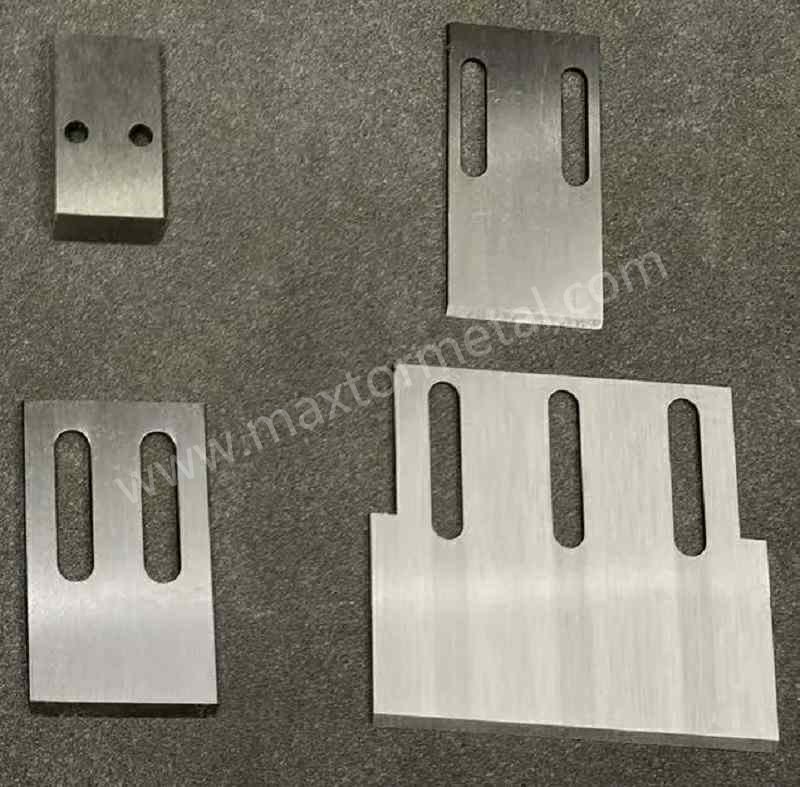
Glass fibers turn an ordinary polyolefin run into an abrasive slurry. Each chopped strand behaves like a microscopic file, accelerating edge rounding on blades and carving faint grooves into the die face. The result? Rising fines and tails, growing vibration, and more frequent blade swaps or regrinds. In die-face/water-ring (underwater) pelletizing of PP/PE with 10–40% glass fiber, this wear shows up faster and costs more in lost uptime and die reconditioning than in unfilled runs.
Abrasion is only half the story. Water chemistry, temperature stability, and alignment also steer how quickly edges dull or chip. If those variables drift, you pay twice—once in pellet quality and again in total cost per ton.
This guide focuses on practical, field-proven choices for underwater systems: blade materials and coatings that resist glass-fiber abrasion, how to pair the blade with the die plate, and the setup and maintenance moves that keep fines down and the die face protected. Throughout, we ground recommendations in OEM and metallurgical sources and use the primary keyword naturally: glass fiber reinforced pelletizer blades.
If your mission is longer life and lower cost per ton, optimizing for glass fiber reinforced pelletizer blades is the most direct lever you control.
Principais conclusões
Glass-filled PP/PE increases abrasive wear, so start with substrates that can take it. Carbide and PM high-vanadium tool steels deliver the longest life; choose carbide for maximum wear life when alignment is excellent, or PM steels when you need toughness and easy resharpening. In underwater chambers, thin, corrosion-aware PVD stacks (for example, a CrN base with a low-friction top) help control friction and wear—just confirm grinding parameters with your coater so edges can be resharpened without delamination. Finally, keep the system balanced: pair compatible blade and die materials, preserve die-face flatness/finish, run the lightest consistent contact, stabilize water temperature/flow and filtration, and maintain disciplined inspection and sharpening cadences with self-aligning hubs where available.
What to measure (so the recommendations are testable)
Track a small set of KPIs every run and tie adjustments to observable signals rather than “feel.” A simple log that includes the items below is usually enough to pinpoint whether you’re fighting blade wear, die-face condition, alignment, or water-loop contamination.
| KPI to track | Why it matters in glass-filled PP/PE | Practical trigger signal (non-numeric) |
|---|---|---|
| Blade life between regrinds / swaps | Direct driver of uptime and cost per ton | Edge radius grows; contact pressure needs frequent increases; tails rise at unchanged settings |
| Fines level (ppm or % by sieve) | Primary pellet-quality complaint in GF service | Dusting increases in conveying; fines collector loads up faster; more “snow” in packaging |
| Tails / whisker rate | Indicates incomplete cut or die-face grooves | Visible tails on pellets; customer cosmetic complaints; downstream screens plug |
| Die-face reconditioning interval | Grooves are the wear accelerator that forces higher pressure | Grooves deepen; witness marks concentrate; pellets show notches or size spread |
| Cutter vibration / noise trend | Proxy for imbalance, uneven contact, or hub wear | Vibration increases at constant rpm; audible chatter during cut |
| Water-loop filtration ΔP and clarity | Recirculated grit drives grooving and edge rounding | Filters load faster; water turns hazy; deposits build on die face |
Operational tip: When a KPI drifts, change only one variable at a time (advance, rpm, melt temperature, water temperature/flow, filtration) and document the before/after so you can lock in the setting window for that formulation.
Blade materials that last
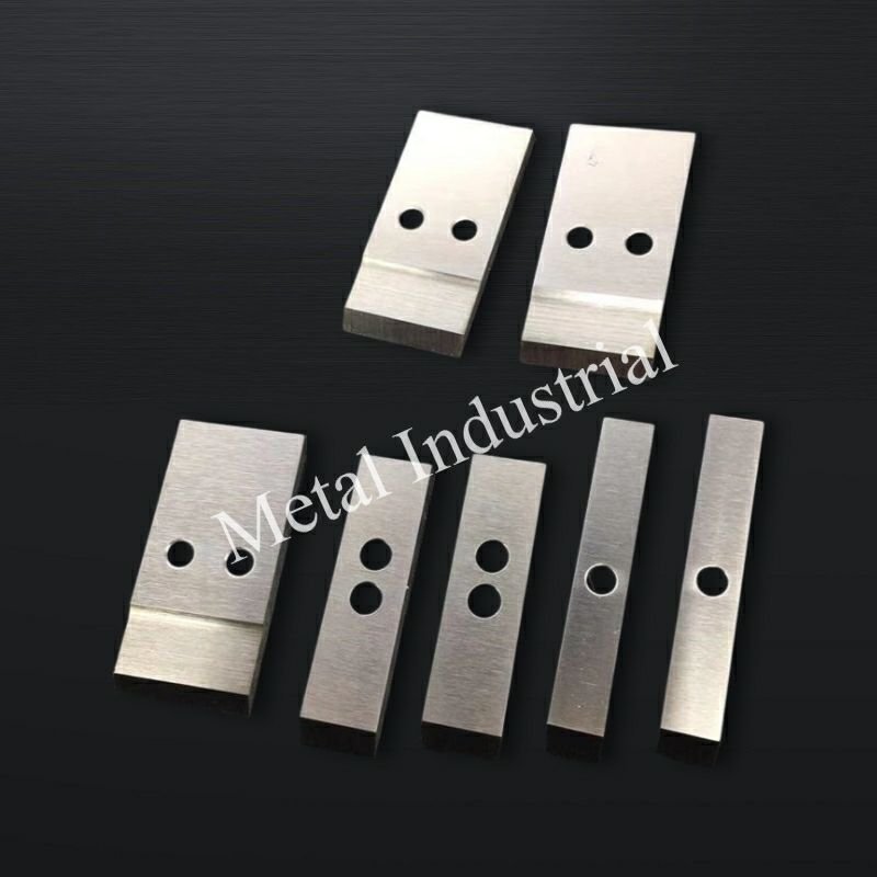
Choosing the right substrate is the single biggest lever for longevity in abrasive, glass-filled service. Think of material choice as setting your “ceiling” for life between grinds, while coatings and setup determine how close you get to that ceiling.
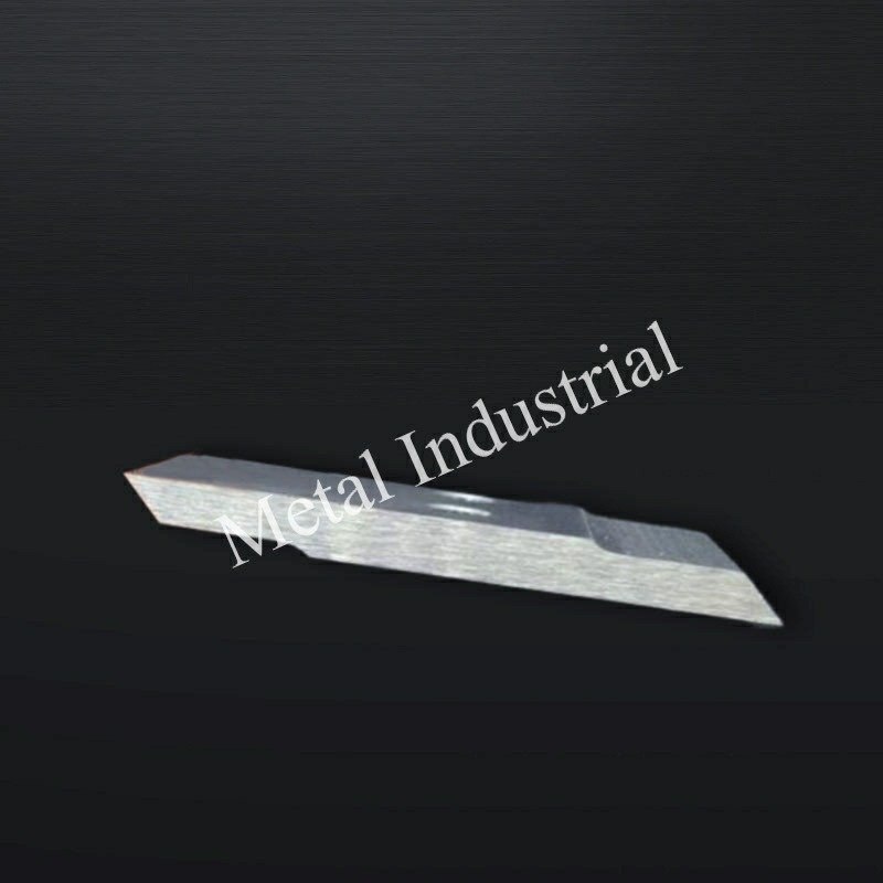
Tungsten carbide options
For maximum abrasive wear resistance, tungsten carbide (including carbide-tipped knives) sits at the top. Its hard carbide phases stand up to the cutting and sliding contact against fiber-laden melt, especially in long, steady runs where alignment is well controlled. The trade-off is lower fracture toughness: under excessive pressure, misalignment, or impact during startups, carbide edges can micro‑chip. Carbide also isn’t as forgiving if blade-to-die contact is aggressive.
Carbide isn’t only for blades—many die faces and wear inserts in polyolefin pelletizing rely on engineered carbides to slow groove formation and reduce reconditioning frequency, as reflected in Kennametal’s pelletizing die portfolio and wear-part overlays for abrasion/erosion duty. See the discussion of hardfacing below and the vendor’s overview of carbide die solutions in the polyolefins space in the following resource: Kennametal pelletizing dies and wear materials (accessed 2026).
When to choose carbide blades: long campaigns on consistent formulations, tight alignment control, and a premium on the longest intervals between regrinds or blade changes.
For procurement teams comparing options, this internal primer on “carbide-tipped pelletizer blades” outlines applications and trade-offs for plastics processing: plastic pelletizer blade product overview.
PM high-vanadium tool steels
Powder metallurgy (PM) high‑vanadium tool steels—analogs to CPM 10V/15V and high-speed families like M4—disperse hard vanadium carbides in a fine matrix, delivering excellent abrasive wear resistance with a meaningful toughness margin over full-carbide. In underwater GF service, that toughness helps resist edge chipping during transient contact or minor misalignment, while still outlasting conventional M2/D2.
Representative datasheets from Uddeholm document the wear/toughness balance:
- Vanadis 8 SuperClean shows very high abrasive wear resistance in cold-work applications with improved toughness relative to D2. See the Uddeholm Vanadis 8 technical sheet (accessed 2026).
- Vanadis 23 and 60 extend the high-wear PM HSS family, with Vanadis 60 reaching the highest wear levels within its class according to Uddeholm’s comparative charts: Vanadis 60 SuperClean (accessed 2026).
When to choose PM steels: you need long life plus reliable resharpening and a buffer against chipping. Many underwater GF lines find PM high‑V steels the best total-cost compromise.
M2 and D2 as baselines
M2 and D2 remain common baselines but expect shorter life in 10–40% GF duty. D2’s chromium carbides improve wear versus simple tool steels, yet PM high‑V grades typically surpass it under severe abrasion. M2’s high-speed steel pedigree offers good hot hardness but trails PM high‑V steels and carbide for abrasive resistance in glass-filled polyolefins. If budget requires M2/D2, consider protective coatings and a tighter sharpening cadence.
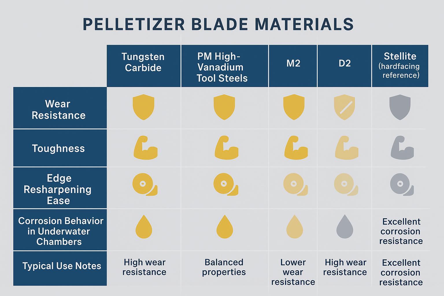
A quick comparison for material selection speed:
| Material | Relative wear resistance | Relative toughness | Resharpening ease | Wet/corrosion behavior | Typical use note |
|---|---|---|---|---|---|
| Carboneto de tungstênio | Mais alto | Mais baixo | Moderate (special wheels) | Good with proper binder; inert surface | Long, steady GF campaigns where alignment is tight |
| PM high‑V tool steels | Muito alto | Medium–high | High (standard grinding) | Good; benefits from protective PVD | Balanced choice for GF where chipping risk exists |
| D2 | Médio | Medium–low | Alto | Moderate; may pit without protection | Budget baseline; pair with coating and tighter cadence |
| M2 | Medium–low | Médio | Alto | Moderate; hot hardness helps | Shorter runs; step-up from basic tool steels |
| Stellite (hardfacing) | N/A (overlay) | N / D | Reconditioned as surface | Good corrosion/erosion resistance | Die-face/wear overlays to delay grooving |
Surface engineering upgrades
Surface engineering fine-tunes friction, corrosion behavior, and edge stability in wet, abrasive service. Two families dominate: thin-film PVD/CVD on blades and hardfacing overlays on dies and wear surfaces.
PVD/CVD coatings for wear control
In underwater chambers, coatings that manage both abrasion and corrosion perform best. Practical stacks often start with a corrosion-aware base (e.g., CrN) for adhesion and chemical stability, with a low-friction, wear‑resistant top (e.g., DLC variants or TiAlN depending on grind and temperature). Industry leaders note PVD’s role in harsh, corrosion/erosion-prone environments; for example, Oerlikon reports coating solutions for demanding wet service applications in its investor and annual communications: Oerlikon investor presentation on advanced PVD applications (2024) (accessed 2026).
Ionbond highlights Tribobond series for corrosive/wear service and describes layer strategies, including pre‑treatments, that support durability in wet environments: Ionbond coating families for corrosive environments (accessed 2026). While not blade‑specific, these sources align with field experience in wet pelletizing chambers.
Use thin films (≈2–4 μm) on cutting edges to preserve geometry and allow controlled resharpening. Always confirm wheel spec, coolant, and feeds with your coater to avoid delamination during grinding.
Hardfacing overlays (e.g., Stellite)
Hardfacing protects the surfaces that must not wear fast—primarily the die face and any wear rings or inserts around the cutting zone. Cobalt‑based Stellite and tungsten carbide overlays are common to slow groove formation from glass fiber abrasion and micro‑entrained particulates. Kennametal’s Conforma Clad documentation describes Stellite 720 and WC-based overlays for abrasion/erosion control in severe industrial environments: Kennametal Conforma Clad — slurry-based cladding overview (accessed 2026).
Coating and sharpening compatibility
- Keep coatings thin and uniform near the edge; avoid overly thick CVD films on sharpened edges unless validated for regrind.
- Coordinate sharpening parameters (wheel type, grit, coolant, pressure) with the coating vendor. Some DLC stacks prefer specific wheel chemistries and low-pressure passes.
- Recoat scheduling should align with your sharpening cadence; track edge geometry so the film is renewed before functional thickness drops below target.
Match blade and die plate
Proper pairing prevents the vicious cycle of grooves → tails → more pressure → faster wear.
Hardness pairing and metallurgy
Avoid extreme hard–hard pairings that risk scoring both components. A slight hardness offset and compatible metallurgies help the system wear in a controlled way. In practice, this means combining a wear‑resistant blade substrate (carbide or PM high‑V) with a die face whose finish and flatness are maintained meticulously, using hardfacing where appropriate. Where available, follow your OEM’s hardness and material pairing guidance rather than adopting generic numbers.
Die-face finish and flatness
Die-face condition is a top predictor of fines and tails. Grooves act like tracks that pull the blade edge, raising load and creating uncut whiskers. Keep the die face flat and smooth; recondition (grind/polish) before grooves propagate. Davis‑Standard’s troubleshooting guidance links poor die-face condition to pellet defects and recommends surface restoration as a corrective action. See: Davis‑Standard troubleshooting for pellet quality issues (2021).
Underwater vs strand considerations
Underwater (die‑face in water) cuts the melt while it’s still soft, lowering mechanical cutting load compared to strand pelletizing—useful with glass-filled compounds that would otherwise punish blade edges when fully solid. Plastics Technology’s overview of underwater pelletizing issues reinforces that water management and temperature balance are central to quality and longevity in these systems: Plastics Technology — mitigating and troubleshooting underwater pelletizing (2020).
For further reading on underwater-specific blade considerations, see this internal overview: underwater pelletizer blades choices guide.
Setup for glass-filled runs
Safety & validation note: Follow your pelletizer OEM’s lockout/tagout and service procedures for any blade change, hub adjustment, or die-face reconditioning. Treat OEM settings as the governing reference. For coated blades, confirm the coating supplier’s approved grinding wheel, coolant, and pass strategy before resharpening to reduce delamination risk.
Dialing in contact, clearance, speed, and thermal balance is where many plants win or lose the fines battle. A small change in one variable can ripple through cut quality and wear rates—so document settings and change only one thing at a time. How do you know which lever to pull first? Start where risk is highest: contact pressure and alignment.
Contact and clearance control
- Set blade advance to achieve clean slicing with the lightest consistent contact. Excess pressure accelerates die-face grooving, especially with glass fibers.
- Verify flat, even contact across the arc. Uneven contact produces localized wear tracks and chipping.
- If your system supports it, use self‑aligning cutter hubs and position monitoring to maintain consistent contact through thermal expansions and minor runouts. MAAG’s catalog covers MAP (manual), EAC (electronic), and other hub designs that help maintain uniform blade‑to‑die positioning in production: MAAG EAC electronically adjustable pelletizer (2026) e MAAG MAP manually adjustable pelletizer (2024).
Speed, load, and heat
- Coordinate cutter speed with melt temperature and die pressure. Cutting too fast on a cool melt raises mechanical load, nudging edges toward rounding or micro‑chipping.
- If you observe “smearing” or tails at constant pressure, consider modestly adjusting cutter rpm or melt temperature to improve cut firmness without overloading the edge.
Cooling and water management
- Keep water temperature and flow within your OEM’s typical PP/PE range (often no need to exceed ~70 °C). Stability matters more than chasing a single number. Rapid quench can create voids or brittle skins that crumble into fines; too warm encourages chaining or stickiness.
- Filter the loop aggressively. Entrained grit (including glass fragments) re‑circulates to the die face and blades, deepening grooves.
- Watch water chemistry (pH, hardness) to limit corrosion that undercuts coatings or promotes deposit formation on the die face.
Maintenance that prevents fines
Illustrative example (not a performance guarantee)
A mid-to-high throughput underwater pelletizing line running PP with ~30% glass fiber begins to see a steady rise in fines and intermittent “tails,” even though the operator keeps increasing blade advance to maintain a clean cut. Inspection shows concentrated witness marks across the cutter arc and early groove formation on the die face.
What was changed (one lever at a time):
- Mechanical: verified hub self-alignment and corrected uneven contact so the blade sweeps the die face more uniformly.
- Process: reduced contact load to the lightest consistent setting, then fine-tuned cutter rpm to stop chatter without smearing.
- Water loop: improved filtration discipline (more frequent element changes and closer ΔP tracking) to reduce recirculated grit.
- Wear parts: switched from a baseline tool steel to a tougher, wear-resistant substrate (often a PM high-vanadium grade in this duty), and used a thin, corrosion-aware PVD stack validated for regrinding.
How success was judged:
- Fines trend stabilized (by sieve checks) and tails became visually rare.
- The required blade advance per shift stopped “creeping up,” indicating slower edge rounding.
- Die-face groove growth slowed, extending the interval before reconditioning.
Note: Your results will depend on formulation, throughput, cutter hub design, die-face metallurgy/finish, and water chemistry. Use the KPI table above to validate changes and document your own settings window.
Preventive routines turn unpredictable chipping and grooving into scheduled touch‑ups. Here’s the deal: don’t wait for fines ppm to spike—use visual and positional indicators to trigger actions earlier.
Inspection and sharpening cadence
Define your sharpening cadence by tracking hours, throughput, and fines ppm. PM high‑V steels often stretch intervals versus M2/D2 in GF service; carbide can run longest if alignment is excellent. Use the lightest practical grind to restore edge geometry and keep coating stacks intact when applied, and plan recoating on a multiple of your sharpening interval. For safe, step-by-step changeovers and service, reference this internal SOP: how to replace pelletizer die face blades safely and efficiently.
Alignment checks and self-aligning hubs
Confirm even contact across the arc at every planned stop; any concentrated witness marks signal misalignment. Verify self‑aligning hub function where equipped; worn pivots or springs defeat constant-pressure intent and drive localized grooving. OEM literature on underwater systems emphasizes these mechanisms because they stabilize blade position under thermal and hydraulic loads: MAAG underwater pelletizing systems category (accessed 2026).
Diagnose wear modes and fixes
Common patterns tell you what to adjust next.
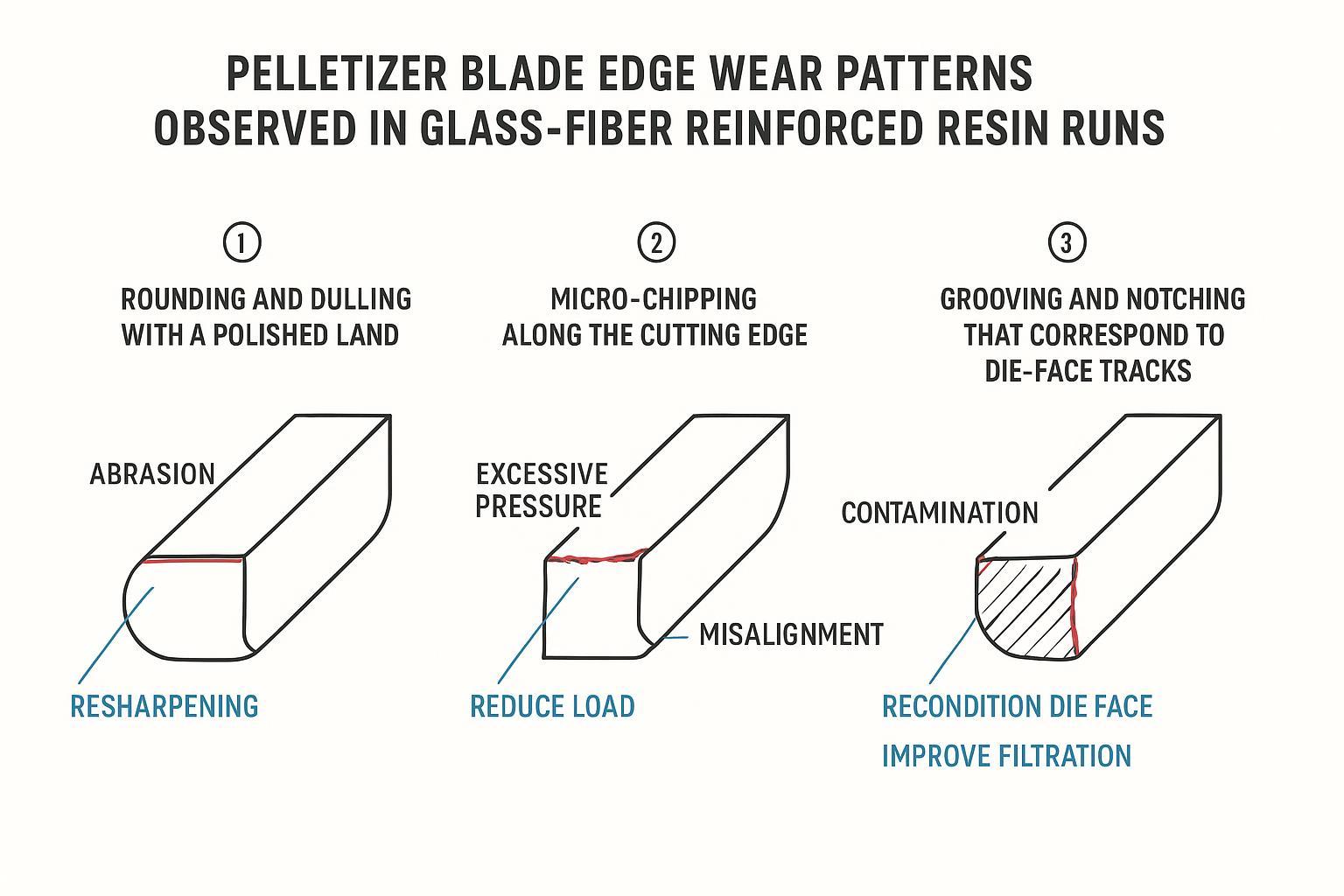
Rounding/polished land typically calls for a slight increase in advance or a resharpen, and sometimes a small rpm or melt-temperature adjustment. Micro‑chipping points to excessive contact pressure or misalignment; reduce load, verify alignment, or select a tougher substrate or different thin‑film stack. Grooving/notching is a die‑face and filtration story first—recondition the face, improve filtration, confirm even contact, and revisit your hardfacing/coating plan.
Conclusão
Abrasive glass fibers punish edges and die faces—but with the right substrate, surface engineering, and disciplined setup/maintenance, you can push longer, steadier campaigns at lower cost per ton. In practice, the winning combo for many underwater PP/PE lines is PM high‑vanadium steel or carbide blades, thin corrosion‑aware PVD stacks where appropriate, immaculate die‑face condition, and alignment systems that hold contact steady.
Checklist — choices that extend blade life and cut fines
- Material: choose carbide for maximum wear life with tight alignment, or PM high‑vanadium steel for toughness plus long life in GF duty.
- Coatings: consider CrN‑based stacks with low‑friction tops; keep films thin and confirm regrind parameters with the coater.
- Blade–die pairing: avoid extreme hard–hard combos; maintain die-face flatness/finish; apply hardfacing where grooves tend to start.
- Setup: set the lightest consistent contact; balance cutter rpm with melt temperature; stabilize water temperature/flow and filtration.
- Maintenance: define sharpening cadence by throughput and fines ppm; verify self‑aligning hub function; diagnose wear patterns early and act.
Tommy Tang is a Senior Sales Engineer at Nanjing METAL with 12 years of experience supporting underwater (die-face/water-ring) pelletizing operations and wear-part selection for abrasive, glass-filled compounds. Credentials: CSE, CME, Six Sigma Green Belt, PMP.
Method note: Recommendations in this guide prioritize OEM manuals, metallurgical datasheets, and observable wear modes (rounding, chipping, grooving). Always validate final blade–die pairing, coating stack, and grinding parameters with your pelletizer OEM and coating supplier.
Further reading and sources
- OEM troubleshooting on pellet defects and die-face condition: Davis‑Standard — troubleshooting common pellet quality issues (2021).
- Underwater system tuning and issues: Plastics Technology — mitigating underwater pelletizing issues (2020).
- Carbide die/wear surface approaches: Kennametal — pelletizing dies overview.
- PM high‑V steels and wear data: Uddeholm — Vanadis 8 technical sheet e Vanadis 60 SuperClean.
- PVD stacks in harsh, wet service: Oerlikon — investor presentation on advanced coating applications (2024) e Ionbond — coating families for corrosive environments.