Nguyên lý Kỹ thuật Dao cắt tròn
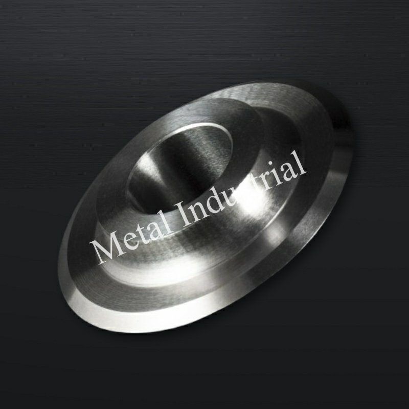
Dao cắt tròn chính xác (còn được gọi là dao xả băng xoay hoặc lưỡi dao cắt tròn) sử dụng động học quay liên tục kết hợp với dao dưới/dao cối (Cắt kéo/Cắt gọt - Shear Slitting), hệ thống lưỡi dao mỏng (Cắt dao rọc - Razor Slitting), hoặc lô đè/lô đe tôi cứng (Cắt ép/Cắt nghiền - Crush Slitting) để thực hiện quá trình xả băng dọc, cắt lát, cuộn lại hoặc tạo lằn liên tục cho các cuộn vật liệu đang chuyển động. Các công cụ xoay tiên tiến này được thiết kế chuyên dụng cho máy cuộn xả băng công suất cao, máy cắt tạo lằn carton sóng và dây chuyền xả băng điện cực pin lithium-ion tự động.
1 Khả năng tương thích hệ thống OEM
Tiêu chuẩn kỹ thuật này được thiết kế để đáp ứng hoặc vượt trội hơn các thông số hiệu suất của các nhà sản xuất máy xẻ cuộn hàng đầu quốc tế, bao gồm Kampf, Atlas, Goebel, Pasaban, Valmet, Dienes, Tidland và ASHE.
2 Ma trận thông số kỹ thuật cốt lõi
| Thông số kỹ thuật | Phân loại điện cực & lá kim loại Li-ion | Màng, băng keo & giấy tốc độ cao | Thép silic hạng nặng & Dây chuyền xẻ cuộn |
| Vật liệu được đề xuất | Tungsten Carbide (WC) siêu mịn | Thép cacbon M2/M42 HSS, SK5, SK7, 1065 | DC53, LD, D2 (1.2379) / SKD11 |
| Ma trận độ cứng | HRA 89 – 93 | HRC 62 – 64 (Thép gió) / HRC 56 – 60 | HRC 60 – 63 (DC53/LD) |
| Phạm vi đường kính ngoài (OD) | 40mm – 350mm | 100mm – 680mm | 80mm – 500mm |
| Dung sai đường kính trong (Lỗ trục) | Lắp trượt chính xác H7 / G6 | Lắp tiêu chuẩn H7 | Lắp chính xác H7 |
| Dung sai độ dày | ± 0.001mm đến ± 0.002mm | ± 0,005mm | ± 0,003mm |
| Độ đảo mặt đầu (Độ đảo hướng trục) | < 0,005mm | < 0,015mm | < 0,010mm |
| Độ đảo hướng kính (Độ không tròn) | ≤0,010mm | ≤0,020mm | ≤0,015mm |
| Độ nhám cạnh cắt (Ra) | Ra < 0.4µm (Đánh bóng gương) | Ra < 0,8µm | Ra < 0,6µm |
| Độ nhám bề mặt bên (Ra) | Ra < 0,8µm | Ra < 1,6µm | Ra < 1,2µm |
| Tiêu chuẩn kích thước | ISO 2768-mK | ISO 2768-mK | ISO 2768-mK |
Tổng quan Kỹ thuật Sản phẩm: Động học Cắt gọt Xoay & Mài mòn Ma sát học (Tribological Wear)
Trong các hệ thống xẻ dọc tốc độ cao hiện đại, cạnh cắt của dao tròn phải chịu các trường ứng suất cắt tuần hoàn phức tạp kết hợp với tốc độ cao mài mòn ba vật thể (three-body abrasive wear). Do dụng cụ quay liên tục, mọi phân đoạn vi mô riêng biệt dọc theo chu vi của lưỡi dao đều trải qua quá trình chuyển đổi nhanh chóng đi vào và đi ra khỏi vùng ứng suất vật liệu, khiến nó rất dễ bị mỏi do tiếp xúc lăn.
1 Động học của vùng chồng lấn cắt (Shear Overlap Zone)
Trong hệ thống xẻ cắt đồng bộ (nơi lưỡi dao nam phía trên chồng lên và giao cắt với lưỡi dao nữ phía dưới), chất lượng của mép xẻ được quyết định bởi cấu hình của hình học chồng lấn:
- Khe hở mặt bên hướng trục: Đối với lá kim loại, polyme cứng và tấm silicon, khe hở ngang vật lý giữa dao trên và dao dưới phải được duy trì nghiêm ngặt trong khoảng từ 0.002mm đến 0.01mm. Nếu vượt quá khe hở này, vật liệu nền sẽ bị uốn cong cục bộ và giãn dài do kéo thay vì bị cắt thực sự, tạo ra các bavia nghiêm trọng. Ngược lại, khe hở không đủ sẽ gây ra hiện tượng ma sát vi mô, buộc ứng suất nén cục bộ tăng theo cấp số nhân và đẩy nhanh quá trình mẻ vi mô. Đối với các vật liệu mềm như giấy và khăn giấy, các thiết lập lò xo sử dụng lực căng trước trục cơ học hoặc khí nén không đổi được áp dụng để đạt được mặt phẳng “khe hở bằng không” tự điều chỉnh. Để biết hướng dẫn hiệu chuẩn và vận hành hoàn chỉnh bao gồm độ chồng chéo, góc nghiêng và áp suất tải trước vi mô trong các hệ thống khe hở bằng không có lò xo, hãy xem Cơ cấu lò xo cho phép cắt rãnh không khe hở.
- Độ sâu chồng chéo: Độ sâu giao nhau theo chiều dọc của lưỡi dao nam vào rãnh dao nữ phải được hiệu chuẩn trong khoảng từ 0.5mm đến 1.5mm. Độ sâu chồng chéo quá mức sẽ làm tăng diện tích tiếp xúc ma sát bên giữa các mặt của lưỡi dao, chuyển hóa động năng quay thành nhiệt năng cục bộ, làm mềm nền martensite của mũi cắt.
2 Vi nứt do mỏi & Động học tạo bụi
Khi máy xẻ tròn vận hành ở vận tốc tuyến tính cao (ví dụ: 400–1200 m/min), bất kỳ sai lệch vi mô nào về độ nhám cạnh (Ra) hoặc tính đồng nhất cấu trúc đều hoạt động như một điểm tập trung ứng suất. Khi lưỡi dao bị cùn, dạng hư hỏng của vật liệu nền sẽ chuyển từ cắt đứt sạch sang nứt vỡ do nén. Sự chuyển đổi này tạo ra các vết nứt vi mô trong các lớp phủ giòn (chẳng hạn như bùn cực catốt pin) hoặc các sợi, giải phóng một lượng lớn các mảnh vụn vi mô và bụi lơ lửng trong không khí. Bụi này có thể bám vào mặt lưỡi dao, làm thay đổi hệ số ma sát (μ) và kích hoạt một vòng lặp nhiệt phá hủy.
Ứng dụng Công nghiệp: Phân tích Chi tiết theo Từng Ngành
1 Xẻ cực điện pin Lithium-Ion
- Vật liệu nền: Lá đồng, lá nhôm và các vật liệu nền được phủ kép bằng các hợp chất hóa học lithium sắt photphat (LFP) hoặc niken-mangan-cobalt (NMC) có tính mài mòn cao.
- Máy móc: Dây chuyền xẻ cực điện pin tự động độ chính xác cao.
- Yêu cầu kỹ thuật: Lớp bùn mài mòn chứa các hạt giống gốm cứng có khả năng ăn mòn mạnh các nền kim loại gốc sắt. Ứng dụng này bắt buộc sử dụng Hợp kim vonfram (WC) hạt siêu mịn với độ cứng HRA từ 89–93. Dung sai độ dày phải được duy trì ở mức ±0.001mm để ngăn ngừa hiện tượng lệch hướng trục, giúp loại bỏ hiện tượng bong tróc lớp phủ và tách mép trên bộ thu dòng điện.

2 Gia công màng polyme tốc độ cao
- Vật liệu nền: Màng BOPP, PET và PI (Polyimide) có độ bền kéo cao.
- Máy móc: Máy cuộn xẻ tốc độ cao Kampf, Goebel và Atlas.
- Yêu cầu kỹ thuật: Các cuộn màng polyme mỏng chạy với vận tốc vượt quá 600 m/min rất dễ bị tích tụ tĩnh điện và lực cản ma sát. Các lưỡi dao tròn mỏng làm bằng Thép lò xo SK5, SK7 hoặc thép lò xo carbon cao 1065 được chỉ định sử dụng. Góc vát cắt phải đạt độ bóng gương Ra < 0.4µm để loại bỏ các rãnh vi mô kéo các chuỗi polyme, ngăn ngừa rách do kéo và hút bụi tĩnh điện.
3 Xẻ thép silicon & Lõi máy biến áp
- Vật liệu nền: Thép lá silicon kỹ thuật điện định hướng và không định hướng có hàm lượng silicon cao.
- Máy móc: Dây chuyền xẻ cuộn tròn hạng nặng.
- Yêu cầu kỹ thuật: Thép silicon tạo ra lực cản biến dạng đàn hồi cực lớn, tạo ra các phản lực pháp tuyến nghiêm trọng trong quá trình cắt xén. Các lưỡi dao D2/SKD11 thông thường thường bị mẻ cục bộ dưới các cú sốc chu kỳ này. Thép DC53 hoặc LD (HRC 60–63) là bắt buộc ở đây, tận dụng sự phân bố cacbua đồng đều của nó để hấp thụ ứng suất cơ học va đập cao.
4 Gia công Prepreg composite tiên tiến
- Vật liệu nền: Prepreg sợi carbon, sợi thủy tinh dệt và vải nhiều lớp tẩm nhựa.
- Máy móc: Các mô-đun dao cắt tròn cấp liệu liên tục.
- Yêu cầu kỹ thuật: Các sợi cấu trúc sở hữu đặc tính mài mòn cực cao làm cùn các cạnh thép tiêu chuẩn chỉ trong vài giờ. Thép gió (HSS) M2 hoặc M42 (HRC 62–64) được tăng cường lớp phủ TiAlN bằng phương pháp lắng đọng hơi vật lý (PVD) được khuyên dùng. Lớp phủ hoạt động như một rào cản nhiệt, bảo vệ độ cứng của cạnh bên dưới chống lại ma sát khô liên tục.
5 Gia công bao bì thực phẩm vô trùng & dược phẩm
- Vật liệu nền: Màng nhôm-nhựa nhiều lớp và màng túi y tế vô trùng.
- Máy móc: Dây chuyền xẻ tuân thủ tiêu chuẩn phòng sạch.
- Yêu cầu kỹ thuật: Để ngăn ngừa hiện tượng bong tách lớp màng và đáp ứng các tiêu chuẩn vệ sinh nghiêm ngặt, lưỡi dao phải chống oxy hóa khi tiếp xúc với độ ẩm hoặc các chất khử trùng. Thép không gỉ Martensite hàm lượng crom cao Thép không gỉ Martensite (420 hoặc 440C) được lựa chọn và tối ưu hóa đạt độ cứng HRC 48–56, đạt được sự cân bằng ổn định giữa khả năng chống ăn mòn và độ sắc bén của cạnh.
6 Xẻ & tạo lằn bìa carton gợn sóng tốc độ cao
- Vật liệu nền: Bìa carton gợn sóng nhiều lớp hạng nặng và giấy mặt.
- Máy móc: Máy xẻ và tạo lằn bìa carton gợn sóng tốc độ cao.
- Yêu cầu kỹ thuật: Lớp sóng chạy ở tốc độ cao và chứa các sợi tái chế mài mòn cùng các hạt silica. Dụng cụ cắt yêu cầu khả năng chống va đập và mài mòn đặc biệt. Thép tốc độ cao M2 được sử dụng rộng rãi, và các lưỡi dao phải được cấu hình với độ đảo trục <0.015mm để loại bỏ hiện tượng đảo bên gây bẹp sóng hoặc tạo ra quá nhiều vụn giấy.
4.Các sự cố hư hỏng thường gặp & Giải pháp Kỹ thuật
1 Vấn đề: Phát sinh bụi xẻ nghiêm trọng
- Nguyên nhân gốc rễ: Các vết mẻ siêu nhỏ dọc theo góc vát mài hoặc khe hở mặt bên theo trục không được hiệu chuẩn sẽ ép lưỡi dao nghiền nát vật liệu nền thay vì cắt đứt nó. Quá trình nghiền cơ học này làm gãy các sợi và lớp phủ, tạo ra lượng mảnh vụn đáng kể.
- Giải pháp kỹ thuật (Mô hình đánh đổi): Chỉ định một Đánh bóng gương siêu mịn on the blade bevels and faces, reducing the roughness to Ra < 0.1µm. While mirror polishing increases production cycle times and manufacturing costs by approximately 20%, it minimizes initial grinding micro-cracks and material dragging, reducing slitting dust by up to 80%. For a comprehensive root-cause analysis covering blade flank Ra, carbide microstructure selection, and the setup tolerances that prevent secondary dust generation—including field measurement protocols and regrinding guidelines—see Root-Cause Analysis of Slitting Dust Generation: Blade Flank Ra, Carbide Microstructure & Setup Tolerances.
2 Vấn đề: Mẻ cạnh không liên tục (Mẻ vi mô)
- Nguyên nhân gốc rễ: High-hardness substrates (e.g., silicon steel, dense coatings) generate normal forces that exceed the fracture toughness of the blade’s alloy matrix. This issue is magnified by the presence of large, segregated primary carbides in standard cold-work steels like D2/SKD11.
- Giải pháp kỹ thuật: Replace D2/SKD11 with DC53 or LD Tool Steel tempered to HRC 60–63. DC53 undergoes a refining process that yields a fine, uniform matrix with double the impact toughness of SKD11, preventing micro-chipping under cyclic loads.
4.3 Problem: S-Curve Profile or “Snake Cuts”
- Nguyên nhân gốc rễ: Excessive Độ đảo mặt đầu (Độ đảo hướng trục) causes the blade to deviate horizontally during rotation. This issue can also be caused by cumulative thickness tolerances across a gang-slitting setup or an inadequate bore-to-shaft fit.
- Giải pháp kỹ thuật: Tighten the blade’s thickness tolerance to ±0.001mm and restrict the maximum allowable axial runout to <0.005mm via dynamic balancing and precision side grinding. Ensure the bore diameter follows an H7 or G6 slide-fit protocol to eliminate shaft eccentricity. For a full systems-level diagnostic checklist covering blade geometry, tension profiles, machine alignment, and material effects—the four subsystem categories where snake cuts originate—see Stopping Snake Cuts in Film Slitting: A Systems Checklist.
4.4 Problem: Adhesive Accumulation and “Galling” (Material Sticking)
- Nguyên nhân gốc rễ: When slitting pressure-sensitive adhesives, protective films, or soft aluminum foils, frictional heat causes adhesive polymers to melt or ductile metal to cold-weld onto the micro-roughness of the blade faces.
- Giải pháp kỹ thuật: Implement targeted surface modification coatings. For adhesive-backed tapes, apply a Hydrophobic Fluoropolymer (PTFE/Teflon) Coating. For non-ferrous aluminum/copper slitting, apply a Lớp phủ Carbon giống kim cương (DLC). The extreme hardness and minimal friction coefficient of DLC stop material transfer at the atomic level. Note that coated blades cannot be conventionally resharpened on their faces; they require specialized edge-only grinding or recoating. For a full engineering comparison of DLC and PTFE coating systems—including wear-limited vs transfer-limited diagnosis, field case data, and QA specification templates—see DLC vs PTFE Coatings for Slitting Blades: Engineer’s Guide.
Hướng dẫn Kỹ thuật Vật liệu: Đặc tính Luyện kim
The rotational kinematics of circular cutting demand tool materials that offer balanced resistance to rolling contact fatigue, compression, and abrasive wear.

- Hợp kim vonfram (WC) hạt siêu mịn
- Metallurgical Matrix: Composed of ultra-fine sub-micron tungsten carbide hard phases bonded within a high-toughness cobalt (Co) matrix, with an average grain diameter of ≤0.6μ m.
- Mechanical Profile: Provides exceptional hardness (HRA 89–93) and excellent resistance to abrasive slurry wear. However, it exhibits low bending strength and high brittleness; any metal-to-metal collision or foreign body impact will cause catastrophic fracturing.
- DC53 / LD Matrix Steel
- Metallurgical Matrix: A cold-work tool steel designed to eliminate the coarse, segregated primary chromium carbides characteristic of traditional D2/SKD11 steels.
- Mechanical Profile: Achieves a heat-treated hardness of HRC 60–63. Its uniform microstructure yields double the impact toughness of SKD11, making it highly effective at preventing edge chipping when shearing high-tensile metals or thick polymers.
- M2 / M42 High-Speed Steel (HSS)
- Metallurgical Matrix: Heavily alloyed with Tungsten (W), Molybdenum (Mo), Chromium (Cr), and Vanadium (V) to form a dense distribution of thermally stable M6C and MC secondary carbides.
- Mechanical Profile: Possesses high “Red Hardness” (retaining structural integrity up to 500°C) and excellent impact resistance. This makes it suitable for high-speed corrugated paper and composite conversion lines experiencing high-frequency friction.
- 440C & 420 Martensitic Stainless Steels
- Metallurgical Matrix: Contains 12%–18% Chromium, which forms a passive chromium oxide film upon thermal hardening, embedded within a tempered martensitic matrix.
- Mechanical Profile: Delivers a controlled hardness of HRC 48–56. It provides reliable protection against oxidation, pitting, and chemical exposure in humid or sterile food and pharmaceutical converting facilities.
Xử lý Nhiệt & Độ cứng: Nguyên lý Biến đổi Nhiệt cấu trúc
The dimensional stability and edge retention of a circular blade depend heavily on its internal crystalline matrix. Thermal processing errors will cause axial warping and distortion under high-speed rotation.
6.1 Multi-Stage Vacuum Gas Quenching & Tempering
To prevent decarburization and surface oxidation, all steel slitter blanks undergo heat treatment inside a high-vacuum furnace operating at 10-3mbar. The blades are brought up through multi-stage preheating cycles to eliminate thermal gradients and prevent warping in thin-disc configurations. They are austenitized at 1020℃-1100℃(depending on the alloy grade) and quenched using high-pressure, high-purity nitrogen gas (6–10 bar). This is followed by three distinct tempering cycles to minimize residual internal stresses.
6.2 Cryogenic Transformation for Ultra-Precise Tolerances
For high-specification applications requiring sub-micron thickness tolerances (±0.001mm), a comprehensive Deep Cryogenic Treatment (Sub-Zero Liquid Nitrogen Soaking at -196°C) is performed:

Cryogenic processing drives the near-total conversion of unstable retained austenite into hardened martensite while precipitating ultra-fine secondary \eta-carbides throughout the matrix. This provides two key engineering benefits:
- Elimination of Thermal Distortion: It prevents microscopic dimensional shift or axial bowing when the blade warms up under high-speed friction, ensuring a true cutting line.
- Extended Wear Life: Field performance data indicates that cryogenically treated slitter blades exhibit a 30% or greater increase in wear resistance compared to conventionally treated alternatives.
7.Hình học Dao & Kỹ thuật Lưỡi cắt
The geometric tolerances of a circular slitter directly impact its rotational stability. Even minor side-to-side variations can cause wavy cut paths or premature tool failure.

7.1 Geometric Tolerance Chains
- Bore-to-Shaft Concentricity: The central bore must be finished to an ISO H7 or G6 tolerance class to establish a precise slide fit with the slitter shaft. A bore clearance error as small as 0.01mm introduces an eccentric rotation axis, magnifying the Radial Runout and causing uneven material engagement.
- Axial Runout Control: Side wobble must be restricted to <0.005mm for high-precision applications and <0.020mm for general converting. Exceeding these limits causes the overlapping faces of the male and female knives to impact each other during rotation, generating micro-shocks that cause chipping, accelerated face wear, and ragged edges.
For a detailed treatment of ISO 286 fit selection, assembled TIR verification, and the assembly practices that keep runout repeatable at speed, see Dung sai và độ lệch tâm lỗ trung tâm: Tối ưu hóa các mối ghép theo tiêu chuẩn ISO 286 cho dao cắt tốc độ cao.
7.2 Bevel Profiling & Cut Dynamics
Blades can be ground to a Single Bevel, Double Bevel, or Compound Bevel configuration, with included angles ranging from 20° to 45°:
- Acute Bevel Angles (20° – 25°): Minimize the specific cutting force (kc) and drag resistance. This configuration is suitable for delicate, non-woven materials and ultra-thin packaging films, though it offers lower structural edge strength.
- Obtuse Bevel Angles (35° – 45°): Provide a robust wedge profile with excellent mechanical backing. This is the standard configuration for processing tough substrates like silicon steel or abrasive mineral-filled sheets.
8.Quy trình Sản xuất & Kiểm tra Chất lượng
- Ingot Metallurgy & Consolidation: High-purity tool steel blanks are processed via Electro-Slag Remelting (ESR). For tungsten carbide, blanks are produced using Hot Isostatic Pressing (HIP) vacuum sintering to ensure a void-free, homogeneous structure.
- CNC Core Machining: Precision turning of the central bore, drive notches, and locating faces to satisfy H7/G6 specifications.
- Vacuum Thermal Modification & Deep Cryogenics: Hardening and subsequent sub-zero processing at -196°C to eliminate residual stresses.
- Double-Disc Parallel Grinding: Multi-pass grinding under constant-temperature coolant lubrication to achieve flat, parallel sides with a thickness tolerance down to ±0.001mm.
- Rotary Edge Bevel Grinding: Using dedicated high-rigidity grinding centers equipped with vitrified diamond wheels to profile the cutting edge to a finish of Ra < 0.4µm.
- Quality Control Protocol:
- Laser Interferometric Axial Runout Verification: Every high-precision blade is evaluated across its entire circumference. Side wobble is mapped and documented to confirm compliance with the <0.005mm internal threshold.
- Surface Profilometry: Direct stylus measurement of the bevel’s surface finish (Ra).
- Multi-Point Rockwell Hardness Mapping: Verifies that the hardness variance across the blade face does not exceed 0.5 HRC.
Nghiên cứu Tình huống: Hiệu suất Thực tế đã được Chứng minh
Case Study A: Lithium-Ion Battery Anode Slitting (Graphite-Coated Copper Foil)
- Client Profile: A tier-one manufacturer of electric vehicle battery cells.
- Initial Problem: The client was utilizing commercial-grade carbide rotary blades with a thickness tolerance of ±0.005mm and an edge roughness of Ra 0.8µm. Abrasive graphite particles caused material to adhere to the blade faces, limiting linear slitting speeds to 200 m/min. Micro-chipping occurred after 15 hours of operation, causing coating delamination and micro-burrs along the copper foil.
- Can thiệp kỹ thuật: Installed Sub-micron Tungsten Carbide Blades featuring a mirror polish of Ra < 0.1µm and a thickness tolerance held strictly to ±0.001mm.
- Quantifiable Outcomes: Face adhesion was eliminated, allowing production speeds to be increased from 200 m/min to 550 m/min (a 175% increase in throughput). Individual blade service life rose from 15 hours to 120 hours between grinds, while micro-dust emissions fell by 88%.
Case Study B: High-Frequency Electrical Silicon Steel Gang Slitting Line
- Client Profile: A steel service center specializing in transformer core laminations.
- Initial Problem: The line used standard D2 (SKD11) circular blades (HRC 58–60) to slit 0.35mm thick grain-oriented silicon steel. The material’s high deformation resistance caused micro-fractures along the blade edges within 32 operating hours. This dulling produced edge burrs exceeding 0.08mm, which caused electromagnetic performance loss in the final transformer stacks.
- Can thiệp kỹ thuật: Đã chuyển sang DC53 Matrix Steel Circular Blades subjected to vacuum quenching and deep cryogenic stabilization, achieving a uniform hardness of HRC 61–62.
- Quantifiable Outcomes: The high fracture toughness of DC53 eliminated micro-chipping. The required resharpening interval was extended from 32 hours to 145 hours of continuous operation. Slit edge burrs were maintained below ≤0.015mm, reducing sheet rejection rates by 92%.
FAQ: Tài liệu Tham khảo Kỹ thuật & Thu mua
- Tại sao dung sai độ dày lại mang tính quyết định khi cấu hình cụm dao cắt dọc nhiều lưỡi (gang-slitting) kết hợp với các vòng định vị (spacer collars)?
- Trong một cụm dao cắt dọc nhiều lưỡi, các sai số dung sai độ dày của từng lưỡi dao sẽ tích lũy dần dọc theo trục. Một sự sai lệch nhỏ chỉ ±0.01mm trên mỗi lưỡi dao có thể dẫn đến tổng dịch chuyển trục tích lũy vượt quá 0.1mm trên một hệ thống gồm 10 lưỡi dao. Sự dịch chuyển này làm thay đổi khe hở ngang hông (side clearance) đã được hiệu chuẩn giữa lưỡi dao trên và dao dưới, gây ra hiện tượng ba-via nghiêm trọng hoặc va chạm mẻ dao. Việc thắt chặt dung sai đơn lẻ xuống mức ±0.001mm sẽ giảm thiểu tối đa sai số tích lũy này.
- Q: What differentiates the metallurgical carbide structure of DC53 from traditional D2/SKD11?
- A: Traditional D2 tool steel contains large, segregated primary chromium carbides (often ≥20μm in diameter) that form brittle networks during solidification. These large carbides can crack under the high normal forces generated when slitting silicon steel. DC53 undergoes a refined chemical modification and processing routine that replaces these large clusters with fine, uniformly dispersed secondary carbides, doubling the material’s impact toughness.
- Q: Our slitting line experiences web weaving and ragged edges on BOPP film at 800 m/min. What should we verify first?
- A: Begin by checking the Độ đảo mặt đầu (Độ đảo hướng trục) of the upper blades using a high-precision dial indicator or laser gauge. If the runout exceeds 0.020mm, the blade will wobble horizontally across the web path, causing a wavy edge profile. Next, verify that the edge roughness is below Ra 0.4µm; rougher edges can snag polymer chains at high velocities, causing localized tearing.
- Q: Can Tungsten Carbide slitter knives be successfully resharpened? What are the key constraints?
- A: Yes, carbide circular knives can be resharpened, but they require a high-rigidity grinding machine equipped with a resin-bonded diamond wheel and a continuous, high-volume flood cooling system. Dry or unstable grinding creates intense localized thermal gradients that induce micro-cracks along the brittle carbide matrix, leading to premature edge failure on the production line.
- Q: How does a mirror-polished finish (Ra < 0.1µm) prevent slitting dust generation?
- A: A mirror polish eliminates the microscopic grinding ridges and furrows present on standard tool edges. This smooth surface lowers the coefficient of friction (μ) between the blade face and the passing web substrate. Without micro-roughness to score or pull on the material, the mechanical separation remains a clean shear, reducing dust emissions.
- Q: What is a spring-loaded “micro-preload” system, and when should it be implemented?
- A: For thin, compliant webs like tissue, cigarette paper, or thin packaging films, setting a fixed physical side clearance with rigid spacers can be difficult. A micro-preload system uses a pneumatic or calibrated spring mechanism to apply a constant lateral force, maintaining a zero-clearance shear plane that prevents the thin substrate from folding between the blades.
- Q: Is dynamic balancing necessary for all circular slitter blades?
- A: Dynamic balancing becomes essential when the slitting line speed exceeds 1000 m/min. At these speeds, even a minor mass asymmetry along the blade’s perimeter generates significant high-frequency centrifugal vibrations. This vibration degrades the stability of the shear plane, accelerating edge wear and causing inconsistent slit quality.
- Q: When should I select a Teflon coating over a DLC coating for a slitting application?
- A: Select a Fluoropolymer (Teflon) Coating when slitting pressure-sensitive adhesives, transfer tapes, or medical dressings, as it provides excellent resistance to adhesive bonding. However, Teflon has low mechanical hardness. For slitting non-ferrous metals like aluminum or copper foil, choose a Diamond-Like Carbon (DLC) Coating; its high hardness resists abrasive wear while preventing metal transfer and cold welding.
- Q: Why is M2/M42 High-Speed Steel preferred for high-volume paper conversion over Tungsten Carbide?
- A: High-speed paper conversion lines frequently encounter web tension fluctuations, splices, and occasional foreign contaminants. While Tungsten Carbide offers excellent wear resistance, its low fracture toughness makes it prone to shattering under sudden tension shocks. M2/M42 HSS provides high red-hardness alongside excellent impact toughness, allowing it to withstand mechanical shocks without structural failure.
- Q: How does a high concentration of retained austenite degrade the field performance of a precision slitter?
- A: Retained austenite is an unstable, high-energy crystalline phase at room temperature. Under the influence of cyclic mechanical stress and frictional heat generated during slitting, it can transform into martensite. This transformation is accompanied by a localized volumetric expansion, which can alter the blade’s flat profile, leading to increased axial runout and a loss of cutting precision.
- Q: Why do 440C stainless steel blades show accelerated dulling when slitting dense composite materials?
- A: 440C is a martensitic stainless steel designed primarily for corrosion resistance. To maintain its stainless properties, a significant portion of its chromium remains within the solid solution matrix, leaving fewer free carbon and alloy elements to form hard vanadium or molybdenum carbides. Consequently, its peak abrasive wear resistance is lower than that of dedicated tool steels like DC53 or M2 HSS.
- Q: What are the consequences of an out-of-round bore tolerance on a slitter shaft assembly?
- A: If the bore tolerance exceeds the H7/G6 specification, the blade will sit loosely on the slitter shaft, creating an eccentric axis of rotation. This eccentricity causes the radial runout to spike, meaning the blade will engage the material at varying depths throughout its rotation, causing cyclic wear and inconsistent cut depths.
- Q: What characteristics make glass fiber prepregs highly abrasive to tool edges?
- A: Glass fibers are composed of amorphous silica filaments with high physical hardness. During slitting, these filaments act as fine abrasives against the cutting edge. If the blade material lacks sufficient secondary carbide volume or hardness, the passing fibers will rapidly erode the matrix, rounding the edge profile.
- Q: What is the recommended maintenance threshold for down-time sharpening schedules?
- A: Blades should be scheduled for resharpening when the micro-edge radius (rβ) dulls to between 0.1mm and 0.2mm, or when the product burr height exceeds quality limits. Waiting for macro-chipping or severe blunting to occur requires the removal of significant material during regrinding, which reduces the total number of sharpening cycles and cuts the overall tool life by up to 60%.
- Q: What is the primary difference between a single bevel and a compound bevel configuration?
- A: A single bevel features one continuous angled plane leading to the cutting edge, providing a sharp profile with low cutting resistance. A compound bevel introduces a secondary micro-bevel at the very tip of the edge. This micro-bevel reinforces the cutting edge against high normal forces and chipping, extending tool life in demanding applications with only a minor increase in cutting resistance.
" Chào mừng bạn đến để hỏi!
Nếu bạn không tìm thấy lưỡi cắt bạn đang tìm kiếm, chúng tôi cũng có thể tùy chỉnh nó, hãy xem “Lưỡi Dao Tùy Chỉnh” của chúng tôi để tìm hiểu cách thực hiện!
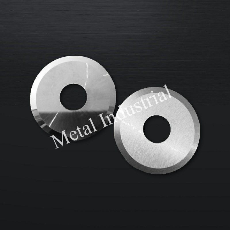
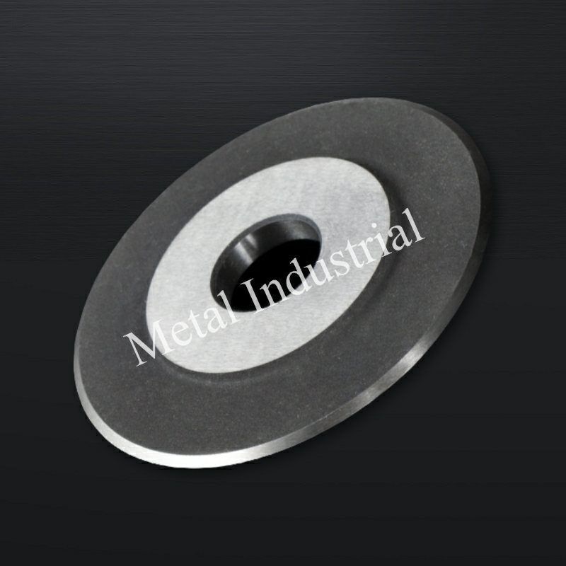
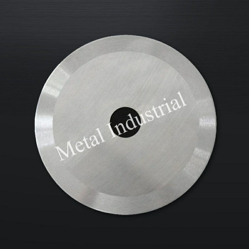
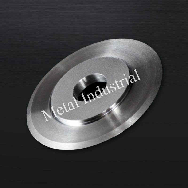
Hiển thị dao tròn:


Tại Sao Chọn METAL?
- Dịch Vụ Nhập Khẩu Trọn Gói, Không Rắc Rối
Tận hưởng sự tiện lợi của việc nhập khẩu liền mạch. Từ vận chuyển đến thông quan, chúng tôi xử lý toàn bộ quá trình. Tất cả những gì bạn cần làm là thanh toán VAT và chờ hàng đến công ty.
- Giá Cả Cạnh Tranh
Chúng tôi đã chứng kiến lưỡi dao của mình xuất sắc trong vô số ứng dụng và sẵn sàng xử lý bất kỳ dự án nào bạn giao phó - mang lại độ chính xác, độ bền và mức giá cạnh tranh không đối thủ.
- ODM & OEM Có Sẵn
Cho dù bạn cung cấp bản vẽ, phác thảo hay mẫu, chúng tôi đều có thể vẽ và sản xuất cho bạn. Chúng tôi cũng có khả năng hỗ trợ sửa đổi các thiết kế và thông số kỹ thuật hiện có để cải thiện hầu hết mọi ứng dụng dụng cụ công nghiệp. Vui lòng liên hệ với đội ngũ bán hàng chuyên trách của chúng tôi để thảo luận về các yêu cầu cụ thể của bạn.
- Kiểm Soát Chất Lượng Nghiêm Ngặt
Một loạt các thử nghiệm và kiểm tra được thực hiện để kiểm soát chất lượng, bao gồm kiểm tra sản phẩm đầu tiên, kiểm tra nguyên vật liệu đầu vào và vật liệu được chứng nhận, kiểm tra chất lượng trong quá trình sản xuất, và kiểm tra chất lượng cuối cùng.
- Mua Sắm Linh Hoạt, Hợp Tác Không Giới Hạn
Dù bạn là nhà nhập khẩu, nhà phân phối, nhà bán buôn hay người dùng cuối, chúng tôi đều chào đón bạn tham gia với MOQ tối thiểu, không rắc rối khi yêu cầu và tự do mua hàng hơn.
- Giám Sát Nước Ngoài, Báo Cáo Tiến Độ Sản Xuất Thời Gian Thực
Trở thành người giám sát độc quyền của bạn, truyền tải thường xuyên mọi nút quan trọng trong dây chuyền sản xuất, dù ở xa đến đâu, tiến độ của sản phẩm sẽ được nắm bắt một cách tốt nhất có thể.



 English