

Những điểm chính:
- Cơ chế chínhViệc tạo ra bụi cắt không chỉ đơn thuần do mép cắt bị cùn; nó chủ yếu được tạo ra bởi ma sát của các vi điểm gồ gề (micro-asperities) trên mặt bên của lưỡi dao khi miết qua mép phôi vừa bị cắt tách.
- Ngưỡng đo lườngViệc giảm độ nhám bề mặt mặt bên của lưỡi dao từ mức thương mại tiêu chuẩn (Ra 0,4–0,8 µm) xuống độ bóng gương siêu hoàn thiện (Superfinished mirror polish Ra < 0,1 µm) giúp giảm ma sát vi mô lên đến 60%, ngăn chặn hiện tượng bong tróc bụi hạt trên các dây chuyền tốc độ cao.
- Lựa chọn luyện kimThép D2 hoặc SKD11 truyền thống thường bị bong tróc hạt cacbua (carbide pull-out) trong quá trình gia công siêu bóng. Để đạt được và duy trì độ bóng bề mặt Ra < 0,1 µm dưới lực căng cuộn liên tục, cần phải sử dụng thép công cụ bột luyện kim (PM-M4) hoặc vonfram cacbua hạt siêu mịn (sub-micron).
- Độ chính xác hệ thốngLưỡi dao bóng gương phải được kết hợp với các dung sai thiết lập cơ khí nghiêm ngặt, bao gồm độ đảo trục ≤ 0,002 mm, góc nghiêng chính xác và độ sâu chồng dao cắt được hiệu chuẩn để ngăn ngừa ma sát thứ cấp.
Bốn nguyên tắc này tạo thành khung kỹ thuật mà đội ngũ ứng dụng của Maxtor Metal áp dụng khi đánh giá chất lượng dao cắt tròn cho các chương trình gia công không tạo bụi trên dây chuyền bao bì mềm, vải không dệt và giấy đặc chủng.
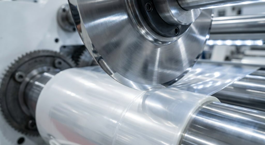
Trong quá trình gia công chuyển đổi tốc độ cao cho bao bì mềm, dệt kỹ thuật, vải không dệt và giấy đặc chủng, sự nhiễm bẩn hạt bụi là nguyên nhân chính gây ra việc dừng dây chuyền ngoài kế hoạch. Những gì các kỹ vận hành nhà máy thường chẩn đoán là "lực căng cuộn kém" hoặc "cuộn nguyên liệu thô bị lỗi" thường bắt nguồn từ một nguyên nhân cốt lõi duy nhất: bụi cắt phát sinh ngay tại điểm cắt kéo (shear cut point).
Khi các vảy polymer vi mô, mảnh xơ sợi hoặc hạt phủ vô cơ tích tụ trên các cuộn phôi đã cắt slitting, các công đoạn xử lý tiếp theo sẽ bị lỗi. Hệ thống kiểm tra quang học phát cảnh báo lỗi giả, mực in xuất hiện các lỗ kim (pinholes) do khoảng trống bụi, và các cuộn phôi tích điện tích bẫy không khí bên trong, dẫn đến hiện tượng trượt cuộn (telescoping) trong quá trình cuộn lại.
Trong khi kiến thức bảo trì truyền thống chỉ tập trung hầu như hoàn toàn vào độ sắc của lưỡi dao (bán kính mép cắt), nghiên cứu ma sát học (tribology) và đo lường thực tế tại xưởng cho thấy bán kính mép cắt chỉ là một nửa vấn đề. Nguyên nhân chính gây ra hiện tượng bong tróc bụi mịn là hồ sơ độ nhám bề mặt của mặt bên lưỡi dao.
Báo cáo kỹ thuật này nghiên cứu cơ học vùng cắt của quá trình cắt cuộn xoay (rotary shear slitting), định lượng tác động của các thông số độ nhám bề mặt (Ra, Rz, Rmax), đánh giá vi cấu trúc của thép công cụ và phác thảo các thông số vận hành cần thiết để đạt được hiệu suất cắt không tạo bụi.
स्लिटिंग डस्ट जनरेशन की माइक्रो-मैकेनिक: कैसे फ्लैंक रफनेस वेब इरोजन (web erosion) को ट्रिगर करती है
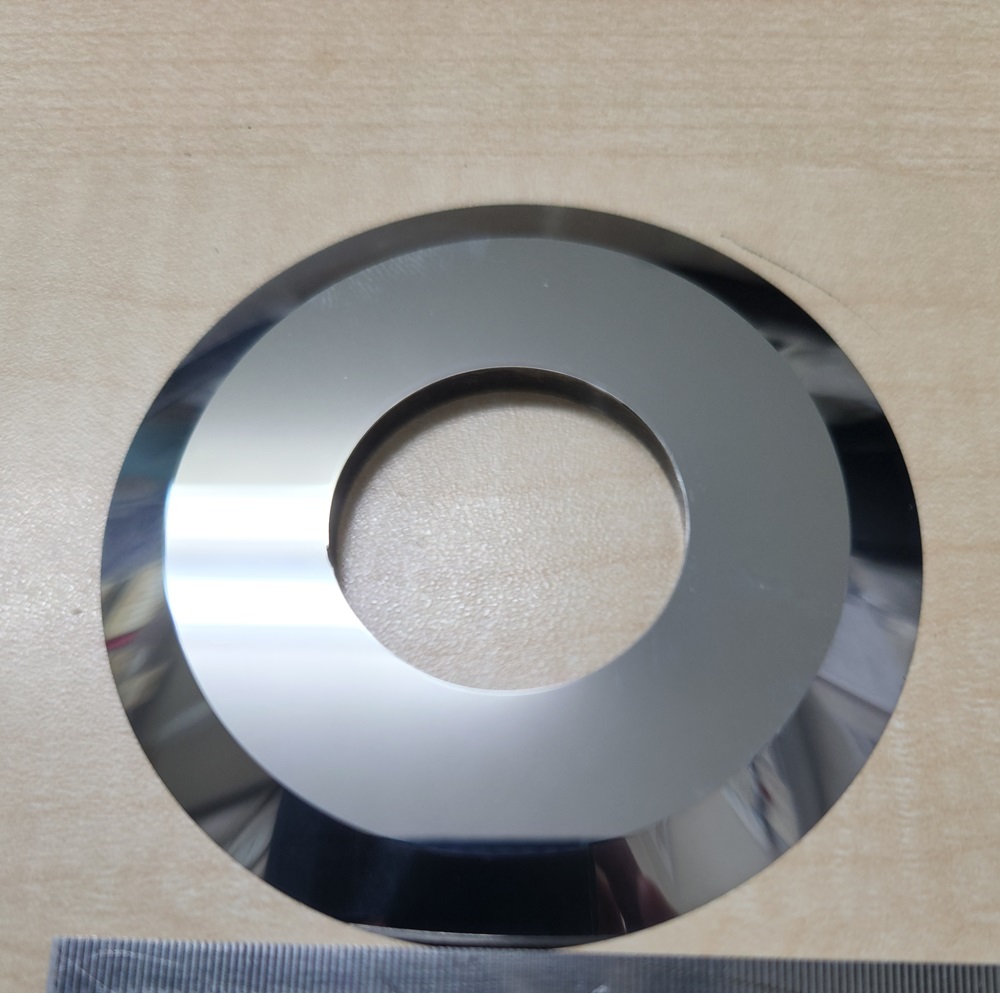
Để loại bỏ sự nhiễm bẩn hạt bụi, các kỹ sư quy trình gia công chuyển đổi phải phân tích quy trình cắt chia cuộn dạng kéo hai giai đoạn. Cắt chia cuộn dạng kéo không phải là hành động cắt bằng lưỡi dao lam đơn giản; đó là một vết nứt cơ học được kiểm soát xảy ra giữa dao tròn dạng đĩa phía trên và cối dao dưới.
Giai đoạn 1: Nén đàn-dẻo → Vật liệu bị ép giữa các cạnh lưỡi dao trên và dưới.
Giai đoạn 2: Khởi phát vết nứt vi mô → Ứng suất cắt vượt quá giới hạn bền kéo; vết nứt lan rộng.
Giai đoạn 3: Tiếp xúc mặt bên & Di chuyển của cuộn vật liệu → Mép cuộn vật liệu bị đứt trượt dọc theo mặt bên của lưỡi dao trên xuống dưới.
Lực cản nhám vi mô so với Vết nứt cắt sạch
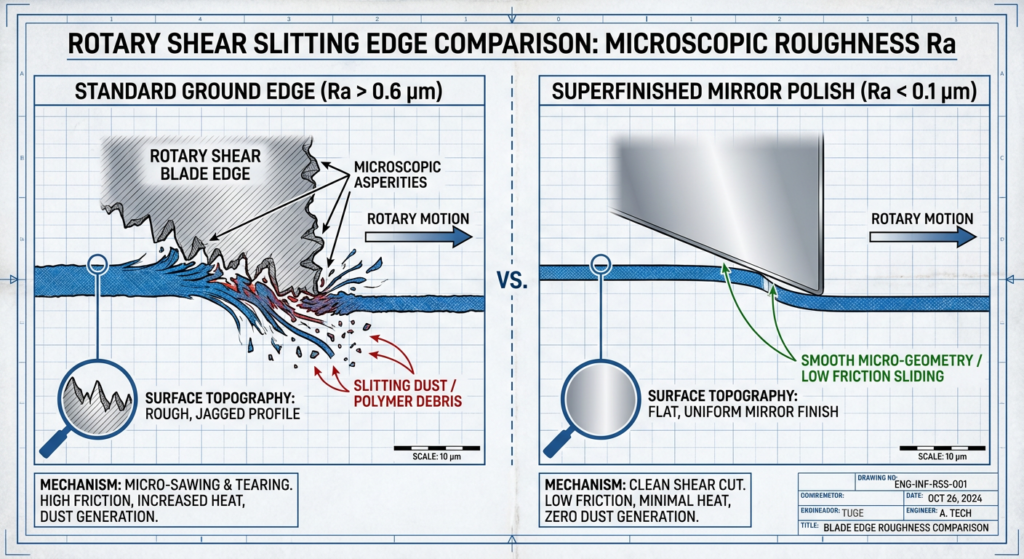
Trong Giai đoạn 3, mép cuộn vật liệu mới tạo ra sẽ di chuyển dọc theo mặt bên của dao tròn phía trên. Khi một lưỡi dao được mài bằng đá mài tiêu chuẩn, đá mài sẽ để lại các đường gờ có hướng gọi là độ nhám vi mô (micro-asperities).
Dưới độ phóng đại quang học 200x, mặt bên của lưỡi dao mài tiêu chuẩn trông giống như một lưỡi cưa siêu nhỏ. Khi mép cuộn vật liệu di chuyển qua các đỉnh nhám này với tốc độ vượt quá 300 mét/phút, các điểm nhám sẽ móc vào các chuỗi polymer hoặc sợi cellulose riêng lẻ. Thay vì được cắt đứt một cách sạch sẽ, vật liệu bị rách vi mô cục bộ, mài mòn và biến dạng cắt. Vật liệu bị rách tách ra thành các hạt mịn lơ lửng trong không khí hoặc mảnh vụn bám tĩnh điện. Điều này khớp với tài liệu kỹ thuật từ các nhà cung cấp dao xả cuộn hàng đầu, trong đó lưu ý rằng bề mặt lưỡi dao thô ráp làm xơ xước các mép cắt khi cuộn vật liệu đi qua mặt bên, và chất lượng mài lại có thể làm tăng lượng bụi ngay cả khi độ bóng đo được có vẻ tương đồng.[2]
Vòng lặp phản hồi mài mòn ba vật thể
Một khi các hạt bụi ban đầu tách ra, chúng sẽ kích hoạt một chu kỳ suy giảm gia tốc:
- Sự kẹt hạt: Các mảnh vụn mịn lọt vào khe hở vi mô giữa góc vát của lưỡi dao trên và vòng cối dao dưới. Hình học góc vát tại mũi dao trên cũng quyết định diện tích tiếp xúc bị ảnh hưởng bởi vòng lặp mài mòn ba vật thể này. Một góc vát vi mô hỗn hợp giúp tăng cường độ bền của mũi dao chống sứt mẻ do hạt gây ra, đồng thời giảm bề mặt bên bị lộ — để biết khung lựa chọn góc vát ưu tiên độ cứng, hãy xem Các loại lưỡi cắt vát đơn, đôi và phức hợp dành cho dao cắt rãnh tròn..
- Mài mòn ba vật thể: Các hạt cứng bị kẹt (chẳng hạn như chất độn canxi cacbonat trong màng nhựa hoặc bột màu titan dioxide trong vải không dệt) hoạt động như một hợp chất mài mòn.
- Trầy xước mặt bên & Độ cùn: Các mảnh vụn làm trầy xước mặt bên của lưỡi dao, làm tăng độ nhám bề mặt đồng thời làm bo tròn cạnh cắt chính.
- Lượng bụi tăng đột biến theo cấp số nhân: Khi bề mặt lưỡi dao trở nên thô ráp và cùn đi, độ sâu của vết rách vật liệu tăng lên, tạo ra lượng bụi lớn hơn.
Độ nhạy của nền vật liệu
Các nền vật liệu gia công khác nhau biểu hiện các dạng hư hỏng riêng biệt khi tiếp xúc với mặt bên lưỡi dao thô ráp:
- Màng BOPP, PET & PE: Ma sát cao tạo ra nhiệt năng cục bộ tại ranh giới cắt. Sự gia nhiệt do ma sát gây ra hiện tượng nóng chảy vi mô, tiếp theo là nứt vỡ nhiệt giòn, tạo ra bột polymer trắng mịn.
- Vải không dệt & Dệt may tổng hợp: Các điểm nhám vi mô móc vào các sợi đơn lẻ, kéo chúng ra khỏi cấu trúc liên kết (xơ sợi) thay vì cắt đứt chúng.
- Giấy tráng phủ & Các-tông: Mặt bên thô ráp làm nứt lớp phủ vô cơ phía trên (đất sét/latex), giải phóng bụi khoáng làm mài mòn nhanh chóng các cạnh thép công cụ.
Phân tích đo lường bề mặt: Tại sao Ra < 0,1 µm là ngưỡng để cắt xẻ không tạo bụi
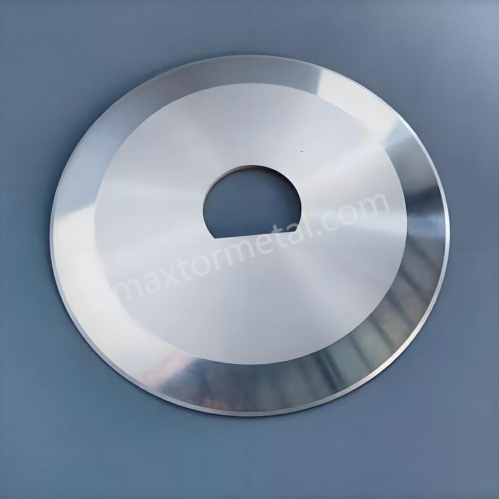
Việc định lượng độ bóng bề mặt đòi hỏi phải vượt ra ngoài các thuật ngữ cảm tính như “được đánh bóng” hoặc “bề mặt sáng”. Các quản lý nhà máy phải chỉ định các thông số đo lường bề mặt bằng cách sử dụng thử nghiệm máy đo biên dạng theo tiêu chuẩn ISO 4287, tiêu chuẩn định nghĩa các thông số biên dạng Ra, Rz và Rmax, và ISO 4288, tiêu chuẩn quản lý cách so sánh các giá trị đo được với giới hạn dung sai.[1]
- Ra (Độ nhám trung bình số học): Trung bình số học của các sai lệch chiều cao biên dạng so với đường trung bình.
- Rz (Chiều cao nhấp nhô trung bình): Chiều cao đỉnh-đến-thung lũng trung bình của năm chiều dài mẫu liên tiếp.
- Rmax: Khoảng cách đỉnh-đến-thung lũng riêng lẻ lớn nhất trên toàn bộ chiều dài đánh giá.
Trong cắt chia cuộn tròn, Ra trực tiếp chi phối ma sát ở trạng thái ổn định, trong khi Rz quyết định liệu các đỉnh nhám có móc vào các sợi của nền vật liệu hay không.
| Phân loại độ bóng bề mặt | Độ nhám bề mặt (Ra) | Chiều cao đỉnh-đến-thung lũng (Rz) | Biên dạng địa hình bề mặt | Mức độ phát sinh bụi cắt | Khả năng tương thích & Giới hạn gia công điển hình |
|---|---|---|---|---|---|
| Mài thương mại | Ra 0,4 – 0,8 µm (16–32 RMS) | Rz 1,6 – 3,2 µm | Các vết mài tròn rõ rệt; các đỉnh vi mô sắc nhọn. | Nghiêm trọng: Bong tróc polymer liên tục và xơ sợi. | Thick rubber trimming or low-speed corrugated board. Unsuitable for films. |
| Precision Ground | Ra 0.2 – 0.4 µm (8–16 RMS) | Rz 0.8 – 1.6 µm | Fine grinding lines; moderate peak height reduction. | Moderate: Acceptable for paperboard under 150 m/min; creates static dust on thin films. | Standard paper converting and basic packaging lines. |
| Superfinished Mirror Polish | Ra < 0.1 µm (2–4 RMS) | Rz < 0.4 µm | Near-frictionless mirror topography; zero directional grinding ridges. | Near-Zero: Smooth sliding contact with clean shear fracture and no material drag. | High-speed BOPP/PET film, battery separators, non-wovens, and medical foils. |
When upgrading from a precision ground finish (Ra 0.3 µm) to a superfinished mirror finish (Ra < 0.1 µm), the kinetic coefficient of friction between the blade flank and web can drop by approximately 50% to 60% in controlled tribometer testing on precision-ground tool steel — a range consistent with Maxtor Metal’s internal comparative testing between Ra 0.3 µm and Ra < 0.1 µm PM-M4 samples under simulated slitting contact conditions.. This reduction helps keep steady-state flank contact below the critical shear stress required to tear material off the cut edge, reducing slitting dust generation at the source.
It is important to frame this threshold correctly. As documented in industry converting engineering guidance, dust generation is not governed by surface finish alone. Engineering references identify several interacting variables that together determine how much dust a line produces: blade sharpness, shear (cant) angle, side load, web material, knife rotational speed, overlap, runout, and web tension. A superfinished blade reduces the flank-driven component of dust, but it must be combined with correct setup geometry to deliver near-zero shedding in production.
Engineers evaluating high-performance converting lines can review precision-ground shear blades and rotary slitting knives to verify how superfinished surface metrology contributes to micro-asperity drag elimination.
Nghiên cứu trường hợp thực tế: Gia công chuyển đổi giấy đặc chủng năng suất cao
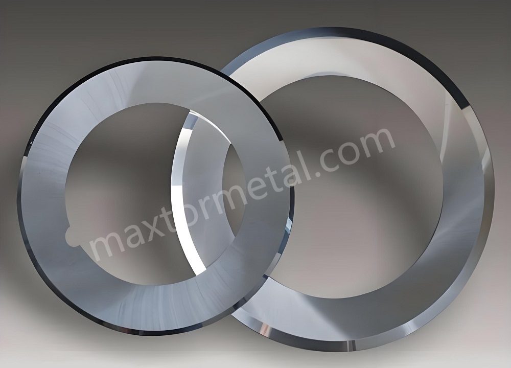
To illustrate how these principles translate to operating performance, consider a continuous, high-volume specialty paper converting plant running on circular shear slitting knives. The line processes approximately 100 tons of roll paper per day in around-the-clock, multi-shift operation, using conventional alloy tool steel circular knives.
| Tham số | Before Upgrade (Conventional Tool Steel) | After Upgrade (Combined Knife & Process) |
|---|---|---|
| Average blade wear life | Đường cơ sở | +250% |
| Slitting dust & debris | Severe airborne dust, rough edges, rapid wear | −85% |
| Converting line uptime | Approximately one maintenance stop every 48 h | +40% |
The failure mechanism observed in this case is directly relevant to the root-cause discussion above. On specialty paper containing calcium carbonate, titanium dioxide, and kaolin clay fillers, the original blade edges dulled progressively over the production run. As sharpness was lost, the cut transitioned from true shearing into sliding, crushing, and tearing against the web, releasing substantially more paper dust. High flank surface roughness was likewise identified as one of the three primary tooling problems on this line.
Data source: Publicly reported supplier field case; customer identity and detailed production records were not disclosed. Reported performance should therefore be treated as supplier-reported field data rather than independently audited test data. The reported −85% reduction in dust and debris was achieved after a combined knife-and-process upgrade. Surface finish was one of the controlled variables addressed, rather than an independently isolated cause. Ra < 0.1 µm should be understood as an engineering control target, not a standalone causal explanation for the field result.
This example reinforces that a superfinished mirror-polish blade (Ra < 0.1 µm) is one necessary element of a zero-dust strategy, but it operates within a wider system of sharpness, geometry, and machine condition. The metrology and metallurgy decisions in the next sections define what such a blade must deliver and how to keep it performing over time.
Maxtor Metal’s application engineering team has observed consistent results in this direction across specialty paper and film converting projects: when superfinished blades (Ra < 0.1 µm, PM-M4 substrate) replace standard precision-ground D2 knives under otherwise identical setup conditions, blade-change intervals driven by dust-related quality stops typically extend by a factor of 2–3×. The Ra threshold and metallurgical selection criteria described in this report reflect the same engineering controls applied in those projects.
Luyện kim và vi cấu trúc: Lựa chọn loại thép duy trì độ bóng bề mặt Ra < 0,1 µm
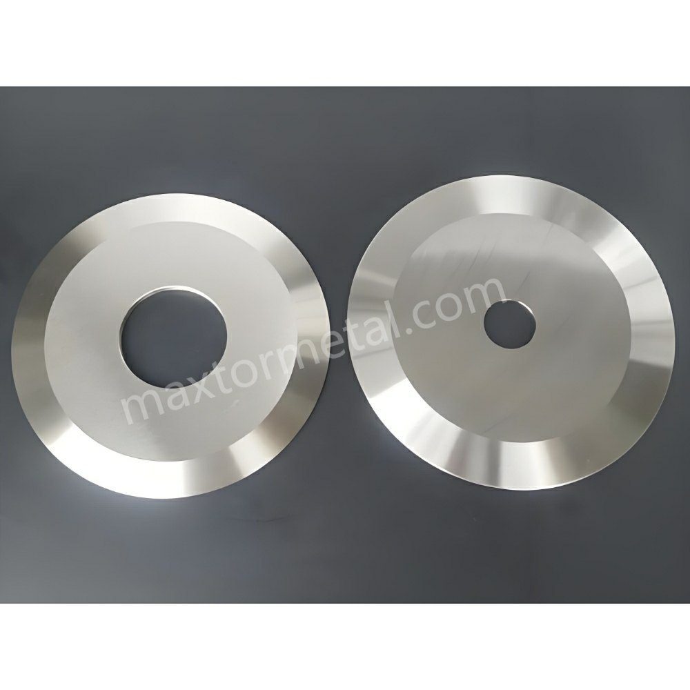
A blade manufacturer can polish an inferior tool steel to a mirror finish in the grinding shop, but if the material’s internal microstructure is unstable, that finish will degrade rapidly under production loads.
The Carbide Pull-Out Pitfall in Conventional D2 / SKD11
Conventional cold-work tool steels like AISI D2 (1.2379 / SKD11) are widely used for industrial cutlery due to their high chromium and carbon content. However, ingot-cast D2 contains large, primary eutectic chromium carbides (M₇C_3) measuring 15 µm to 30 µm in size.
When grinding technicians attempt to superfinish D2 down to Ra < 0.1 µm, the diamond lapping wheel catches these large, brittle carbides and tears them out of the softer martensitic matrix. This phenomenon, known as carbide pull-out, leaves microscopic pits across the blade flank. These micro-pits collect debris and create sharp cavity edges that act as abrasive sites during high-speed slitting.
Powder Metallurgy (PM) and Fine-Grain Carbide Solutions
To maintain an Ra < 0.1 µm surface without carbide pull-out, converting operations must transition to advanced metallurgical alloys.[3] Powder-metallurgy grades such as PM-M4 provide a fine, uniformly distributed vanadium-carbide structure that is far more suited to ultra-fine finishing than the coarse chromium-carbide clusters found in conventional D2.
- Powder Metallurgy Steels (PM-M4, PM-A11 / CPM 10V): Produced via gas atomization and hot isostatic pressing (HIP), PM steels feature ultrafine, spherical vanadium carbides (VC) evenly distributed throughout the matrix. Carbide sizes remain under 2 µm, enabling continuous lapping to Ra < 0.05 µm without micro-pitting.
- Micro-Grain Tungsten Carbide: For high-abrasion applications (lithium-ion battery separator films, glass-filled non-wovens), fine-grain tungsten carbide (0.5–0.8 µm grain size) with 10–12% cobalt binder provides extreme hardness (HRC 75–80) while maintaining a flawless mirror finish over months of continuous operation.
Processing plants requiring high-durability tooling can explore industrial circular slitter blades crafted from powder metallurgy and micro-grain tungsten carbide alloys.
| Steel Grade Comparison for Superfinishing Retention | Detail |
|---|---|
| Conventional D2 / SKD11 | Coarse Carbides 20µm → Carbide Pull-Out → Micro-Pitting (Ra Degrades) |
| PM-M4 / CPM 10V Steel | Fine Carbides < 2µm → Smooth Lapping → Retains Ra < 0.1 µm Finish |
| Tungsten Carbide (Fine) | Sub-Micron Grains → Mirror Polish → Maximum Wear & Zero Dust |
Deep Cryogenic Treatment (-185°C)
After vacuum heat treatment and triple tempering, premium circular knives undergo deep cryogenic treatment at -185°C (-300°F) for 24 hours. Cryogenic processing converts residual retained austenite into stable martensite while precipitating microscopic eta-carbides. This stabilizes the steel matrix, preventing dimensional distortion and preventing stress-induced surface roughening during high-speed rotation. The sequence in which cryogenic treatment, heat treatment, and final lapping are ordered matters as much as the treatment parameters themselves — this process discipline is covered in the next section.
A First-Party Engineering Perspective: Why Finish Retention Outlasts Finish Achievability
A common misconception among converters is that an Ra < 0.1 µm mirror polish is simply a grinding-shop deliverable. In practice, the harder problem is retention under service — keeping that finish through heat treatment, handling, mounting, and high-speed contact. This is where process sequence matters more than the final grinding pass.
From Maxtor Metal’s own shop-floor experience across paper, plastics, and metal-slitting lines, three sequence decisions consistently separate blades that hold a mirror finish from blades that merely start with one:
- Cryogenics Before Lapping: When deep cryogenic stabilization precedes ultra-fine diamond lapping, the austenite-to-martensite conversion is complete before final grinding. Lapping then acts on a dimensionally stable matrix, so the polished surface does not “rewarp” or shed as-transformed carbides in service. Sequence these steps in the reverse order and the finish is vulnerable to surface roughening within weeks of operation.
- Finish Ground on the Mounting Reference, Not as a Standalone Blank: Superfinished flanks are most stable when lapped after the bore and lateral faces are final-ground to their ±0.001 mm tolerances (see the runout section). Lapping a blank first, then grinding the bore, risks re-introducing micro-distortion at the very flank that defines dust performance.
- Documented Material Traceability: Requiring EN 10204 Type 3.1 mill certificates and batch-level traceability means the carbide distribution — and therefore the finish-retention capability — is verifiable on paper, not just on the surface. This turns an otherwise invisible metallurgical claim into an auditable control variable.
These sequencing principles are not found in generic tool-grade datasheets; they reflect first-party process knowledge accumulated through dedicated zero-dust converting programs. For teams planning a Ra < 0.1 µm upgrade, treating the process order with the same rigor as the final Ra number is the single most practical lever for lasting, measurable dust reduction.
Ma trận thiết lập máy: Kiểm soát các yếu tố phụ gây ra mảnh vụn cắt xẻ
While specifying superfinished blades with Ra < 0.1 µm removes the primary cause of dust, incorrect machine setup can force even the best knife to rub against the web, reintroducing debris.
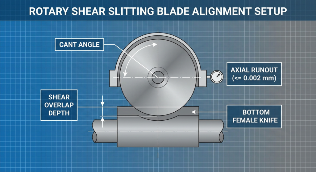
Shear Overlap Depth and Cant Angle Calibration
The interaction between the top circular knife and bottom female slitter must mimic a precise pair of scissors:
- Cant Angle (Side Angle): The angle at which the top dished blade leans into the bottom knife band. Too high a cant angle (> 1.0°) causes excessive point-loading, accelerating flank wear and creating steel dust. Too low an angle (< 0.2°) leads to blade separation and web tearing. For superfinished blades, maintain a cant angle between 0.35° and 0.50°. Maxtor Metal’s field engineering team uses this window as the commissioning baseline when setting up superfinished circular knives on film and nonwoven slitting lines; angles outside this range are the most common setup cause of premature mirror-finish degradation in the first 48 hours of production.
- Shear Overlap Depth: Top blade penetration into the bottom ring should be kept to the minimum required for a clean cut (typically 0.5 mm to 0.8 mm for films under 200 microns). Excessive overlap increases the contact arc distance between the weband the blade flank, increasing rubbing and dust generation. For a detailedtreatment of how overlap, cant angle, and preload interact during shearslitting setup, see Cơ chế lò xo giúp cắt rãnh không khe hở: Điều khiển độ chồng chéo, góc nghiêng và tải trước. For a DOE-based analysis of how overlap depth and side clearance trade off against each other across substrate families—with Pareto data on edge quality vs knife life—see Tối ưu hóa độ sâu chồng chéo và khoảng hở bên của dao cắt tròn.
Axial Runout Control (≤ 0.002 mm) and Spindle Alignment
If the slitter arbor or knife holder exhibits axial wobble (runout), the shear clearance fluctuates with every rotation. This dynamic wobble forces the blade flank to slap against the slit edge twice per revolution, causing cyclic micro-fractures and periodic dust spikes.
Top dished knives and female bottom slitter knives must be ground with lateral thickness tolerances of ± 0.001 mm and mounted on precision-ground expansion arbors to ensure total axial runout remains ≤ 0.002 mm. On multi-knife gang setups, this ±0.001 mm per-knife tolerance accumulates across the arbor stack—a small per-blade variance can shift calibrated shear clearance by enough to trigger secondary rubbing and dust across multiple lanes. For the stack-up math and spacer-matching discipline that prevents this, see Kiểm soát dung sai độ dày tích lũy trong quá trình cắt bằng nhiều dao.
Maxtor Metal verifies axial runout on all finished circular slitting knife assemblies against this ≤ 0.002 mm threshold as a final inspection gate, with results documented in the batch inspection record.
For a measurement-first approach to diagnosing the axial and radial TIR components that drive these dust spikes—including cold-to-hot drift verification and the defect signatures each runout mode produces—see Axial Runout, Dynamic TIR, and Slit Edge Quality.
For the upstream bore-fit decisions that establish the locating baseline from which axial runout is controlled—ISO 286 H7/h6 vs H7/g6 selection, GD&T coaxiality targets, and assembled TIR verification routines—see Dung sai và độ lệch tâm lỗ trung tâm: Tối ưu hóa các mối ghép theo tiêu chuẩn ISO 286 cho dao cắt tốc độ cao.
For lines where runout is also contributing to snake cuts or lane drift, see Stopping Snake Cuts in Film Slitting: A Systems Checklist.
For lines where blade coating is also under consideration alongside surface finish — particularly whether DLC or PTFE coatings affect flank friction and cleaning intervals at the Ra level specified here — see Hướng Dẫn Chọn Lớp Phủ DLC vs PTFE Cho Dao Phân Cuộn/Dao Cắt Biên: Giới Hạn Mài Mòn vs Giới Hạn Bám Dính.
Quy trình kiểm tra tại xưởng: Bảo trì lưỡi dao gia công siêu bóng (Superfinished)
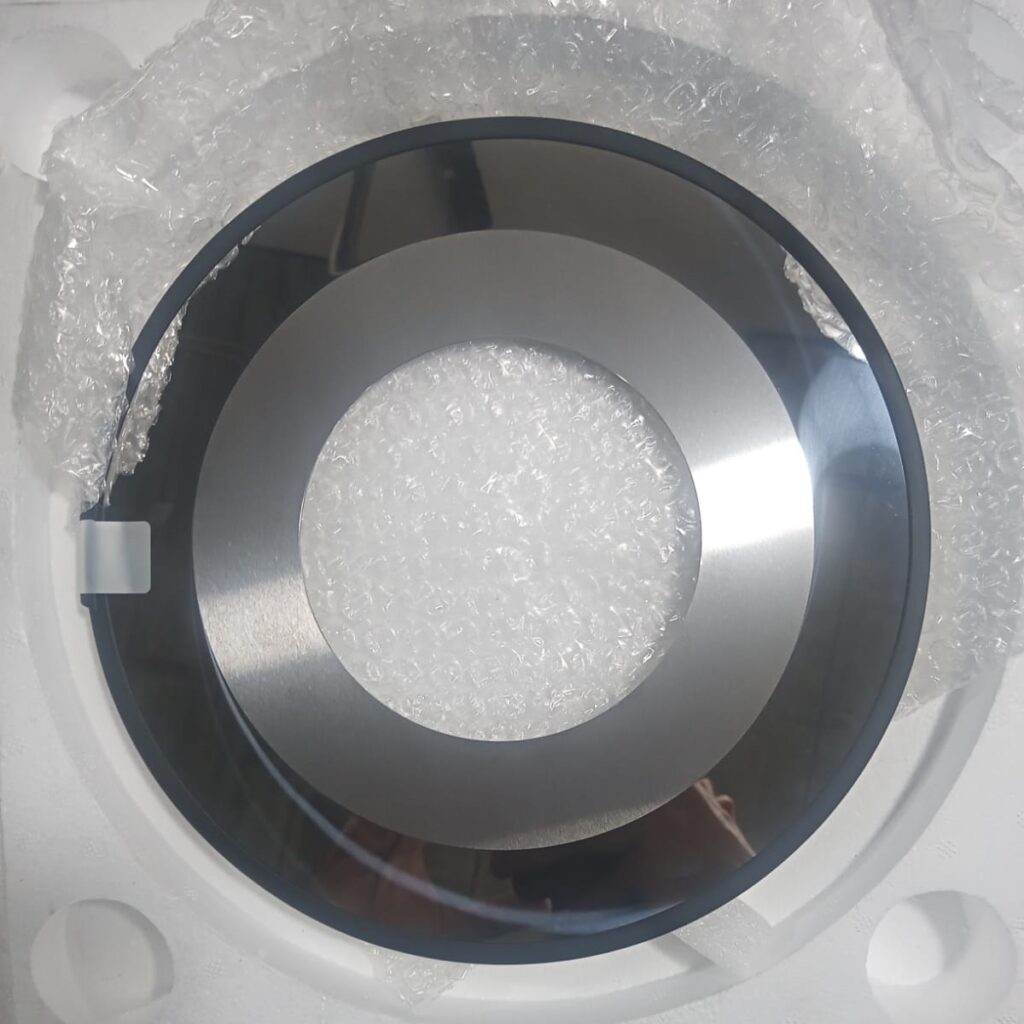
To sustain zero-dust slitting performance across multi-shift production, plant quality teams should adopt a structured inspection routine.
Portable Profilometer Inspection Protocol
- Measurement Location: Take three profilometer readings on the primary bevel flank at 120° intervals around the circular knife.
- Rejection Threshold: If average surface roughness exceeds Ra 0.18 µm or if individual peaks show Rz > 0.6 µm, schedule the blade set for precision re-lapping.
- Kiểm tra cạnh cắt: Inspect the cutting edge under a 50x portable shop microscope. Any micro-chipping exceeding 0.005 mm in depth will act as a dust generator and requires regrinding.
Quantifying Dust Reduction: Measurement Protocols That Stand Up to Audit
To make dust-control claims defensible (rather than marketing assertions), converting plants should pair each improvement with structured evidence:
- Profilometer Measurement: Record Ra / Rz on the flank bevel before and after each blade change using a calibrated contact profilometer, averaging at least three traces 120° apart per ISO 4288.
- Edge Microscopy: Capture fixed-magnification (50x–200x) before/after images of the slit edge to document the transition from frayed, roughened edges to clean fracture faces.
- Dust Collection: Standardize dust sampling at a consistent location and method (for example, a fixed-area tape lift or gravimetric filter catch near the cut point) so results are comparable across blade sets and shifts.
This three-part protocol lets a plant attribute measured dust reduction to the correct variable combination — blade finish, geometry, or process setpoint — rather than overstating the effect of any single control.
Lapping and Precision Regrinding Guidelines
Regrinding superfinished blades on standard toolroom wheel grinders will destroy the Ra < 0.1 µm surface finish. This is consistent with supplier guidance that most converting applications require at least an eight RMS finish, while the highest-speed paper slitting lines demand a super finish of under one RMS to control dust.[4]
- Wheel Selection: Use fine vitrified CBN (Cubic Boron Nitride) wheels for PM steels or resin-bond diamond wheels (1200–2000 mesh) for tungsten carbide.
- Secondary Superfinishing: After primary angle grinding, pass the blades through a two-step diamond lapping process using diamond paste (1–3 µm grit) to restore the mirror finish.
- Demagnetization: Demagnetize all blades to under 2 Gauss after grinding. Residual magnetism attracts fine steel and iron dust, which gets carried directly into the web cut zone.
Những câu hỏi thường gặp (FAQ)
C1: Nguyên nhân chính gây ra bụi cắt trên các dây chuyền gia công tốc độ cao là gì?
Bụi cắt sinh ra chủ yếu do ma sát giữa cuộn phôi và mặt bên của lưỡi dao. Khi mặt bên lưỡi dao có các vết mài thô (Ra > 0,4 µm), các điểm nhấp nhô vi mô này sẽ mài mòn và vướng vào mép phôi khi di chuyển downweb, gây ra hiện tượng vi xé cục bộ và giải phóng bụi mịn polymer hoặc xơ sợi.
C2: Tại sao độ nhám bề mặt bên lưỡi dao (Ra) lại quan trọng hơn đối với việc kiểm soát bụi so với chỉ riêng độ sắc của mép cắt?
Độ sắc của mép cắt quyết định mức độ dễ dàng bắt đầu vết nứt cắt ban đầu, nhưng độ nhám bề mặt bên lại quyết định hành vi của mép phôi khi trượt qua lưỡi dao ở tốc độ cao. Một lưỡi dao sắc như dao cạo nhưng có mặt bên thô ráp vẫn sẽ làm tưa mép phôi và tạo ra nhiều bụi do lực cản của các điểm nhấp nhô vi mô.
C3: Tôi nên yêu cầu thông số kỹ thuật độ nhám bề mặt nào để cắt màng phim không tạo bụi?
Đối với màng bao bì mềm (BOPP, PET, PE), vải không dệt kỹ thuật và lá kim loại phủ, hãy chỉ định độ bóng gương siêu hoàn thiện (superfinished mirror polish) với Ra < 0,1 µm (2–4 RMS) và Rz < 0,4 µm. Đây chính là thông số kỹ thuật mà Maxtor Metal sử dụng làm tiêu chuẩn nghiệm thu cho tất cả các dao cắt tròn cung cấp cho các dây chuyền gia công màng phim và vải không dệt tốc độ cao.
C4: Tại sao thép công cụ D2 truyền thống lại không giữ được độ bóng gương trong quá trình siêu hoàn thiện (superfinishing)?
Thép D2 truyền thống chứa các carbide crom sơ cấp kích thước lớn (15–30 µm). Trong quá trình mài rà kim cương tinh (diamond lapping), các hạt carbide lớn này bị bong tróc ra khỏi nền thép (hiện tượng carbide pull-out), tạo ra các vi lỗ (micro-pits) tích tụ mảnh vụn và làm thô ráp mép cắt. Thép thiêu kết bột (PM-M4) hoặc hợp kim carbide vonfram hạt mịn (tungsten carbide) tránh được vấn đề này nhờ cấu trúc carbide dưới micron của chúng.
C5: Độ đảo trục (axial runout) ảnh hưởng như thế nào đến lượng bụi cắt?
Độ đảo trục (sự đảo mặt) trên trục gắn dao khiến khe hở bên giữa lưỡi dao trên và lưỡi dao dưới mở ra và khép lại trong mỗi vòng quay. Sự chao đảo động này gây ra ma sát và sự đè nén theo chu kỳ lên mép phôi, dẫn đến các đợt phát tán bụi định kỳ và bavia mép cắt. Độ đảo trục phải được duy trì ở mức ≤ 0,002 mm. Maxtor Metal ghi nhận số đo này trong hồ sơ kiểm tra lô hàng cho tất cả các cụm dao cắt tròn thành phẩm như một tiêu chuẩn nghiệm thu bắt buộc.
C6: Dao cắt siêu hoàn thiện (superfinished) có thể mài lại trên các máy mài xưởng tiêu chuẩn không?
Tidak. Roda gerinda standar meninggalkan bekas gerinda yang kasar (Ra 0,4–0,8 µm) yang menghilangkan manfaat dari superfinish. Penggerindaan ulang harus dilanjutkan dengan proses lapping presisi menggunakan senyawa CBN halus atau pasta berlian (pasta 1–3 µm) untuk mengembalikan finis permukaan Ra < 0,1 µm.
Các bước tiếp theo: Nâng cấp dây chuyền xẻ cuộn của bạn lên độ chính xác không tạo bụi
Eliminating slitting dust generation requires a systematic approach combining advanced tool metallurgy, superfinished surface metrology, and rigid machine alignment. By replacing standard commercial ground knives with superfinished (Ra < 0.1 µm) powder metallurgy circular blades, converting plants can eliminate web edge contamination, prevent optical defect triggers, and extend blade service life.
Maxtor Metal manufactures custom precision-ground circular slitting knives, shear blades, and bottom female bands engineered specifically to eliminate edge debris in high-speed converting. Every blade undergoes deep cryogenic treatment, ultra-fine diamond lapping, and complete material certification (EN 10204 Type 3.1) to guarantee consistent, zero-dust performance.
Quality is verified through an independently audited framework. The company is certified to Tiêu chuẩn ISO9001 (quality management systems) and holds SGS third-party inspection certification, and production runs under an ISO-based “in-line” quality assurance regime with a multi-stage inspection gate (first-article, incoming material, in-process, and final inspection) on every order. These externally audited credentials give engineers a documented assurance trail that mirrors the root-cause discipline described throughout this report.
To review technical drawings or request custom knife grinding specifications for your converting line, contact the engineering team at Maxtor Metal.
Tài liệu tham khảo
- ISO 4287 — Geometrical product specifications (GPS) — Surface texture: Profile method — Terms, definitions and surface texture parameters; ISO 4288 — Rules and procedures for the assessment of surface texture.
- TAPPI (Technical Association of the Pulp and Paper Industry), Troubleshooting slitter blade wear — blade edge smoothness and ground surface finish criteria relevant to slit quality and dust generation on slitting lines; and TAPPI, Roll and Web Defect Terminology (Chapter 5: Slitter Defects), which classifies slitter dust and edge-quality defects such as fuzzy edge and dust in roll.
- Powder metallurgy high-speed and tool-steel grade documentation covering carbide size distribution and finish-holding capability: Z-M4 PM (PM-M4) Tooling Alloys Data Sheet, Zapp Precision Metals; Và CPM 10V (AISI A11) Data Sheet, Crucible Industries.
- Industry converting references on knife surface-finish requirements: TAPPI, Troubleshooting slitter blade wear (ground surface finish not exceeding 16 micro-inches for utility slitting); and Converting Quarterly, Ten web defects due to slitting (very smooth knife surface finish — 8 RMS or lower — to reduce excessive dust creation).
- ISO 9001:2015 — Quality management systems — Requirements (ISO international standards catalog). Maxtor Metal’s quality management is certified to ISO 9001 and additionally verified through SGS third-party inspection.
- ISO 21940-11 — Mechanical vibration — Rotor balancing — Part 11: Procedures and tolerances for rotors with rigid behaviour, Và ISO 20816-1 — Mechanical vibration — Measurement and evaluation of machine vibration, as applied to slitter arbor balancing and spindle condition.
- EN 10204 — Metallic products — Types of inspection documents (Type 3.1 mill certificate with batch-level material traceability). Official European standard; catalog/purchase entry via national standards body: NEN-EN 10204:2004 (Netherlands Standardization Institute).
- Maxtor Metal in-house quality assurance regime — ISO-based “in-line” inspection including first-article, incoming material, in-process, and final inspection on precision-ground circular slitting knives.
Về tác giả
Jerry Chu — Technical Support Specialist, After-sales Service, Maxtor Metal
With 10 years of cross-industry application experience spanning paper, plastics crushing, metal slitting, and wood processing, Jerry specializes in diagnosing on-site cutting issues such as edge burr formation and excessive dust generation. He holds PMP and CMRP certifications, bringing project-management rigor and reliability-engineering perspective to blade selection and line optimization. For field troubleshooting support, contact Maxtor Metal’s after-sales engineering team.

 English
  Spanish
  Italian
  French
  Portuguese
  Russian
  German
  Arabic
  Hindi
Hindi  Vietnamese
  Indonesian
  Japanese
  Korean