1.Hệ thống Dao cắt hạt nhựa hiệu suất cao
Tài liệu này thiết lập các tiêu chuẩn kỹ thuật chính xác, khung lựa chọn luyện kim và chẩn đoán vận hành cho dao cắt hạt nhựa hoạt động trong hệ thống cắt hạt dưới nước, máy cắt hạt vòng nước và hệ thống cắt nóng đỉnh đầu khuôn (hot-face).
Giới thiệu về Maxtor Metal — Nanjing Metal Industrial Co., Limited
Maxtor Metal là nhà sản xuất dao công nghiệp chính xác có trụ sở tại Trung Quốc, với hơn 15 năm kinh nghiệm chuyên sâu trong sản xuất các hệ thống dao cắt hạt nhựa theo yêu cầu. Dao cắt hạt nhựa do Maxtor Metal sản xuất hiện đang được vận hành trên các hệ thống cắt hạt của Coperion, Gala, BKG, Automatik và EREMA tại các nhà máy của khách hàng ở Đức, Pháp, Ý, Anh, Hoa Kỳ, Mexico, Chile, Argentina và Đông Nam Á. Sách trắng này trình bày khung kỹ thuật cốt lõi trong thiết kế dao, lựa chọn vật liệu và phương pháp kiểm tra chất lượng của chúng tôi.
Bảng 1: Các thông số kỹ thuật chính & Giới hạn vận hành
| Chỉ số kỹ thuật | Phạm vi thông số tiêu chuẩn | Dung sai công nghiệp & Quy trình thử nghiệm |
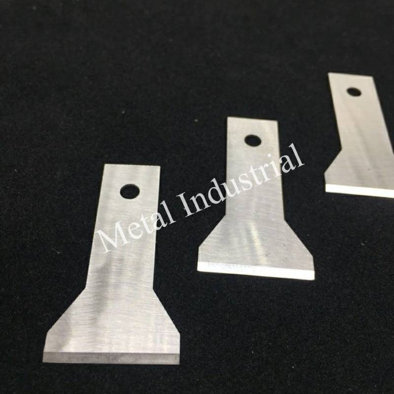
| Biên dạng độ dày lưỡi dao | 8 mm – 2.0 mm (Lưỡi dao dạng tấm mỏng); 5.0 mm – 15.0 mm (Khối xẻ rãnh hạng nặng) | Độ đồng đều chiều dày ±0.010 mm được hiệu chuẩn qua panme kỹ thuật số |
| Góc vát cắt (α) | 20° đến 45° (Tùy thuộc vào ứng dụng) | ±0.5° được xác minh qua thiết bị đo góc quang học |
| Độ phẳng bề mặt tiếp xúc nhựa nóng chảy | ≤0.03 mm (Giới hạn tuyệt đối trên toàn bộ phạm vi cắt hoạt động) | Đo giao thoa dải sáng đơn sắc / Thử nghiệm độ đảo bằng đồng hồ so |
| Độ nhám cạnh cắt (Ra) | Ra 0.8 μm (Tiêu chuẩn thương mại); Ra 0.4 μm (Đánh bóng cấp độ quang học/elastomer) | Đo biên dạng bằng đầu dò tiếp xúc dọc theo góc vát mài chính |
| Tốc độ vận hành | 000 vòng/phút – 4.000 vòng/phút | Cấp cân bằng động G2.5 theo tiêu chuẩn ISO 1940 |
| Giao diện căn chỉnh kẹp | Các rãnh căn chỉnh tiêu chuẩn / lỗ thông định vị chính xác | Tuân thủ ISO 2768-mK (Được triệt tiêu bởi lực căng trước bằng khí nén/thủy lực dọc trục) |
Nguồn: Sách trắng kỹ thuật Maxtor Metal — Hệ thống dao cắt hạt hiệu suất cao & Dao cắt hạt dưới nước. Nanjing Metal Industrial Co., Limited. 2026. Mọi thông số kỹ thuật đều dựa trên dữ liệu sản xuất và kiểm chứng thực tế của Maxtor Metal.
2.Tổng quan về Kỹ thuật Sản phẩm
1 Động học và Cơ học ma sát học của bề mặt cắt
Khung vận hành của hệ thống cắt hạt dưới nước hoặc cắt hạt vòng nước tạo ra một môi trường ma sát học được xác định bởi một Cơ chế tiếp xúc trực tiếp / Khe hở bằng không. Không giống như các hoạt động cắt kim loại công nghiệp thông thường sử dụng một khe hở lưỡi dao bên xác định, dao cắt hạt nhựa phải được ép cơ học trực tiếp vào mặt mài chính xác của khuôn đùn gia nhiệt. Sự toàn vẹn cấu trúc của hạt polyme thành phẩm phụ thuộc hoàn toàn vào sự tiếp xúc vật lý chặt chẽ, liên tục giữa cạnh dao chuyển động và mặt khuôn tĩnh.
Lực dọc trục được tác dụng liên tục thông qua các xi lanh khí nén, lò xo cơ học hoặc hệ thống định vị thủy lực bố trí ở phía sau cụm trục cắt. Lực dọc trục không đổi này (Fa) triệt tiêu lực nâng thủy động học do nước làm mát tạo ra và lực đẩy nhớt của polyme nóng chảy thoát ra từ các lỗ phun cực nhỏ của khuôn. Ở chế độ vận hành tiêu chuẩn (1,000 đến 4,000 RPM), cạnh cắt thực tế tồn tại ở trạng thái bôi trơn ranh giới hoặc bôi trơn hỗn hợp. Màng bôi trơn bao gồm một lớp cực mỏng của chính polyme nóng chảy kết hợp với lớp ranh giới hơi nước/nước hóa hơi. Màng chất lỏng này ngăn chặn sự hàn dính vĩ mô tức thời của thép công cụ vào ma trận tấm khuôn, nhưng nó lại khiến cạnh cắt phải chịu các trường cắt vận tốc cao liên tục và các gradient nhiệt cục bộ.
2 Cơ chế hao mòn và suy thoái
Sự suy thoái của biên dạng lưỡi dao diễn ra theo ba con đường nhiệt động lực học và cơ học riêng biệt: mài mòn cơ học, mài mòn dính và rỗ ăn mòn cục bộ.
- Mài mòn cơ học (Hai vật thể và Ba vật thể): Tác nhân chính là các chất độn cấu trúc trong ma trận polyme, chẳng hạn như sợi thủy tinh cắt ngắn (GF), sợi cacbon, titan điôxit (TiO2), canxi cacbonat (CaCO3) và bột talc. Khi polyme nóng chảy được đùn ra ở nhiệt độ từ 180°C đến 320°C, các hạt khoáng cứng này hoạt động như những chiếc máy cày siêu nhỏ mài sát vào cạnh cắt. Dưới cơ chế mài mòn ba vật thể, các sợi thủy tinh bị gãy sẽ bị kẹt giữa góc vát lưỡi dao và tấm khuôn, làm tăng nhanh quá trình tạo rãnh siêu nhỏ và phá hủy biên dạng góc vát chính.
- Mài mòn dính và Hàn nguội: Chiếm ưu thế khi xử lý các polyme có mô-đun thấp, độ bám dính cao như Polyurethane nhiệt dẻo (TPU), Chất đàn hồi nhiệt dẻo (TPE), Ethylene-Vinyl Acetate (EVA) và các công thức keo nóng chảy cụ thể. Sự kết hợp giữa nhiệt ma sát cục bộ và áp suất dọc trục cao buộc polyme nhớt bám dính vào các nhấp nhô bề mặt siêu nhỏ của thép làm dao. Khi lưỡi dao quay ra khỏi lỗ phun, polyme bám dính sẽ kéo rách các cụm vi mô của ma trận dụng cụ, dẫn đến việc cạnh dao bị cùn nhanh chóng và gây ra hiện tượng lem polyme sau đó.
- Rỗ ăn mòn và Suy thoái liên hạt: Gây ra do tiếp xúc liên tục với các vòng tuần hoàn nước được duy trì ở nhiệt độ từ 40°C đến 90°C. Môi trường này thường tích tụ các chất dễ bay hơi có tính axit dạng vết (chẳng hạn như axit axetic giải phóng trong quá trình xử lý EVA, hoặc các axit halogen hóa giải phóng từ các chất phụ gia chống cháy). Thép gia công nguội không gỉ tiêu chuẩn sẽ chịu các cuộc tấn công điện hóa cục bộ nhanh chóng dọc theo ranh giới hạt, làm mất ổn định ma trận liên kết cacbit và dẫn đến hiện tượng mẻ vi mô dưới tải trọng va đập.
3.Ứng dụng Công nghiệp & Thông số Vận hành
Hoạt động cắt hạt nhựa trải dài trên nhiều lĩnh vực công nghiệp rất đa dạng. Việc lựa chọn cấu hình lưỡi dao phù hợp đòi hỏi phải cô lập các biến số xử lý cụ thể như chi tiết dưới đây:
Bảng 2: Ma trận ứng dụng trong các lĩnh vực xử lý
| Lĩnh vực công nghiệp | Thiết bị xử lý mục tiêu | Polyme đùn & Hàm lượng chất phụ gia | Tác nhân mài mòn chính | Lựa chọn luyện kim & Biên dạng hình học khuyến nghị |
| Trùng hợp khối hóa dầu | Máy tạo hạt quy mô lớn Coperion / BKG (>1,000,000 t/a) | LDPE, HDPE, Homo-PP nguyên sinh (Không chứa chất độn mài mòn) | Ma sát trượt liên tục tốc độ cao; mỏi nhiệt | Maxtor Metal WC-Ni Series (Sintered WC-Ni Inserted Block); Bevel: 45° |
| 2. Glass-Fiber Reinforced Compounding | Twin-screw compounding lines (Gala / Automatik) | PA6, PA66, PBT, PPA + 30% to 50% Glass Fiber | Severe high-stress two-body and three-body abrasive wear | Maxtor Metal PM-390 Grade (Monolithic M390 / CPM S90V Powder Metallurgy Stainless Steel); Bevel: 30°–35° |
| 3. Highly-Filled Masterbatch Production | High-torque compounding systems | PP/PE + 70%-80% CaCO3 or Talcum powder | Continuous low-stress abrasion; micro-plowing of matrix | Maxtor Metal HSS-M2 Grade (M2 / CPM 1V High-Speed Steel); Bevel: 35° |
| 4. Thermoplastic Elastomers & Adhesives | Water-ring and underwater cutting systems | TPU, TPE, EVA, Hot-Melt formulations | Adhesive cold-welding; die face agglomeration (smearing) | Maxtor Metal SS-440C / Stellite Series with Teflon-F or DLC-PVD Coating; Bevel: 20°–25° |
| 5. Medical Grade & Food Packaging | Strict zero-contamination closed loops | Medical PVC, PP, Surgical Grade Elastomers | Corrosive oxidation; zero toleration for metal particulate/rust | Maxtor Metal Medical-SS Grade (420 / 440C Martensitic Stainless, Ra ≤0.4 μm Mirror Finish); Bevel: 30° |
| 6. Post-Consumer Plastic Recycling | EREMA, Starlinger recycling lines | Recycled rPET, rPP, rHDPE flakes with tramp metal/sand trace contaminants | High-impact shock; unpredictable catastrophic chipping | Maxtor Metal D2-HT Grade (D2 / SKD11 Cold Work Tool Steel, High-Toughness Temper Protocol); Bevel: 40° |
Nguồn: Sách trắng kỹ thuật Maxtor Metal — Hệ thống dao cắt hạt hiệu suất cao & Dao cắt hạt dưới nước. Nanjing Metal Industrial Co., Limited. 2026. Mọi thông số kỹ thuật đều dựa trên dữ liệu sản xuất và kiểm chứng thực tế của Maxtor Metal.
4.Các sự cố hư hỏng thường gặp & Giải pháp Kỹ thuật
4.1 Polymer Smearing, Tails, and Chain Formation (Chains & Smearing)
- Nguyên nhân gốc rễ: The primary cutting edge has dulled beyond critical geometry, or the blade has developed micro-warpage. The cutting mechanism changes from clean mechanical shear to viscoelastic tensile tearing. Viscous melt stretches out before breaking, creating an extended polymer “tail” or merging adjacent pellets into chains.
- Giải pháp: Enforce strict blade flatness limits (≤0.03 mm) across the active span. Upgrade the tool steel from standard D2 to M2 High-Speed Steel to exploit its superior red hardness, or transition to M390 to prevent abrasive edge recession.
- Sự đánh đổi trong kỹ thuật: Increasing blade hardness reduces material ductility, which increases the structural risk of edge cracking if tramp metal enters the pelletizing chamber.
4.2 Accelerated Die Plate Face Scuffing and Gouging
- Nguyên nhân gốc rễ: The chosen blade metallurgy or hardness profile exceeds the wear-resistance threshold of the die plate’s protective overlay (e.g., ferro-titanium or tungsten carbide tiles). If a high-hardness tungsten carbide blade suffers micro-chipping, the fractured particles become trapped in the interface, acting as a highly abrasive media that scores the expensive die face.
- Giải pháp: Transition to a sacrificial blade philosophy. Utilize Stellite 6 or Stellite 12 Cobalt-base alloy blades. Stellite maintains high hot-hardness and corrosion resistance but limits its absolute hardness to HRC 45-55, ensuring the blade wears smoothly and evenly while protecting the costly die face.
- Sự đánh đổi trong kỹ thuật: Lower blade hardness increases the frequency of blade replacement cycles but avoids catastrophic capital expenditure on die plate rebuilds.
4.3 Die Face Agglomeration (Melt Inability to Detach)
- Nguyên nhân gốc rễ: Highly elastic or tacky materials (TPU, EVA) adhere to the micro-roughness (Ra > 0.8 μm) of the blade’s leading edge and ground bevel. The polymer melt fails to cleanly detach and wrap into a sphere, causing it to build up around the center of the cutter hub and freeze the system.
- Giải pháp: Refine the ground bevel surface finish to a semi-mirror or mirror finish (Ra 0.4 μm). Apply a specialized hydrophobic fluorocarbon (Teflon) or physical vapor deposition (PVD) Diamond-Like Carbon (DLC) coating to lower the surface energy of the steel.
- Sự đánh đổi trong kỹ thuật: PVD/Teflon coatings are thin (2-4 μm) and wear off quickly in abrasive environments, requiring frequent recoating if abrasive fillers are present. For a mechanism-first guide to diagnosing and resolving knife gumming in TPU and EVA underwater pelletizing — covering DLC vs PTFE coating selection, operating window validation, and KPI logging — see TPU underwater pelletizing knife gumming: DLC vs PTFE coating selection and operating windows.
4.4 Corrosive Pitting and Micro-Chipping Along the Bevel
- Nguyên nhân gốc rễ: Operation within warm water loops (60°C–90°C) combined with acid-liberating polymers induces localized galvanic corrosion. Chromium-depleted zones in standard D2/SKD11 steels undergo selective dissolution, causing the carbide matrix to destabilize and drop out during high-velocity impact.
- Giải pháp: Replace cold-work tool steels with high-chromium martensitic stainless steels (440C) or advanced powder metallurgy options like M390 or CPM S90V, which feature a minimum of 17-20% free chromium in solid solution.
- Sự đánh đổi trong kỹ thuật: High-chromium stainless alloys require specialized, highly controlled vacuum heat treatment cycles to prevent the formation of network chromium carbides that lower macroscopic impact toughness.
4.5 Transverse Thermal Fatigue Cracking (Heat Checking)
- Nguyên nhân gốc rễ: Severe cyclic thermal shock occurs as the blade edge sweeps across the hot die plate (240°C–280°C) and immediately plunges into the cold turbulent water flow (40°C–70°C). High-stiffness, low-thermal-conductivity materials expand and contract unevenly, generating localized tensile stress fields that lead to cracking.
- Giải pháp: Lower the absolute hardness by 2-3 HRC points and execute multiple high-temperature tempering cycles to optimize the matrix toughness. Alternatively, transition to Stellite or specific high-alloy high-speed steels that offer excellent thermal shock resistance.
- Sự đánh đổi trong kỹ thuật: Lowering the hardness reduces the blade’s resistance to pure abrasive wear, increasing the wear rate in glass-fiber compounding applications.
4.6 Macro-Brazing Delamination on Composite Heavy-Duty Blades
- Nguyên nhân gốc rễ: Large, thick-slotted blocks utilizing brazed Tungsten Carbide (WC) inserts can separate at the joint due to high mechanical shear and thermal stress cycles during startup. Poor wettability of the braze alloy or residual internal cooling stresses weaken the interface bond.
- Giải pháp: Mandate high-vacuum brazing utilizing advanced Ag-Cu-Ti (Silver-Copper-Titanium) active structural braze alloys. Implement mandatory post-braze Non-Destructive Testing (NDT) via high-frequency ultrasonic scanning to verify that the joint has a minimum bond area of 98%.
- Sự đánh đổi trong kỹ thuật: Vacuum active brazing significantly elevates manufacturing lead times and production costs compared to manual induction brazing methods.
4.7 Instantaneous Mechanical Blade Buckling and Distortion
- Nguyên nhân gốc rễ: Attempting to use ultra-thin carbide inserts or hard-faced materials in a 1.0 mm thick blade profile. The intense localized thermal stress and cutting impacts cause the thin cross-section to distort, resulting in high mechanical runout and catastrophic failure.
- Giải pháp: Maintain a strict engineering ban on carbide-brazed composites for blade thicknesses ≤2.0 mm. For thin blade configurations requiring extreme wear resistance, utilize monolithic powder metallurgy tool steels (such as M390) that maintain high structural homogeneity.
- Sự đánh đổi trong kỹ thuật: Monolithic powder steel blades have a lower absolute hardness than tungsten carbide, meaning they require more frequent sharpening cycles.
4.8 Fine Polymer Dust and Fluff Generation (Fluff/Dust Contamination)
- Nguyên nhân gốc rễ: A micro-rounded cutting edge acts as a blunt wedge rather than a clean shearing tool. Instead of cutting the polymer strand cleanly, it compresses and shears the plastic melt past its ultimate yield strength, scraping off micro-fragments that turn into airborne or water-suspended dust.
- Giải pháp: Reduce the cutting edge radius by utilizing specialized ultra-fine grit diamond grinding wheels during the final sharpening stage. Consider adjusting the primary bevel angle down to 30° or 25° to enhance the sharpness of the tool profile.
- Sự đánh đổi trong kỹ thuật: A sharper, narrower bevel angle reduces the structural mass backing the cutting edge, which accelerates micro-chipping when processing highly filled materials.
4.9 Edge Blunting from Excessive Dynamic Blade Float
- Nguyên nhân gốc rễ: Insufficient axial force applied to the hub allows high-pressure water loops to force the blade slightly away from the die plate. This micro-gap allows the polymer melt to enter the interface, cooling instantly and forcing the blade to roll over the solidified material, rounding the cutting edge.
- Giải pháp: Recalibrate the pneumatic or hydraulic pressure systems at the rear of the cutter shaft to ensure stable contact pressure across the die face. Ensure that the blade mounting hub runs true and does not suffer from axial play or shaft runout.
- Sự đánh đổi trong kỹ thuật: Increasing the axial contact force accelerates mechanical wear on both the blade edge and the die plate surface due to higher frictional loads.
4.10 Rapid Edge Recession due to Secondary Hardening Over-Tempering
- Nguyên nhân gốc rễ: Selecting high-speed steels (like M2) and running them under excessive axial force without sufficient water cooling can elevate blade tip temperatures above the alloy’s initial tempering temperature, causing the martensitic matrix to break down and soften.
- Giải pháp: Increase the cooling water flow rate across the cutter face to maximize heat extraction. Optimize the heat treatment protocol by implementing a triple tempering cycle to ensure high thermal stability up to 560°C.
- Sự đánh đổi trong kỹ thuật: Triple high-temperature tempering slightly lowers the material’s initial room-temperature hardness compared to a low-temperature single temper.
5.Hướng dẫn Kỹ thuật Vật liệu
Table 3: Metallurgical Classification and Performance Vector
| Material Classification | Metallurgical Microstructure & Alloying Elements | Hardness Capability | Engineering Strengths & Limitations |
| D2 / SKD11 / 1.2379 (Cold-Work Tool Steel) | Conventional ingot metallurgy; coarse primary chromium carbides (M7C3) distributed within a tempered martensite matrix. | HRC 58 – 61 | Strengths: Highly cost-effective; easily ground with standard wheels; high compressive strength. Hạn chế: Coarse carbides are prone to micro-chipping; limited corrosion resistance leads to pitting in warm water loops. |
| M2 / High-Speed Steel (1.3343) (Molybdenum-Tungsten HSS) | Balanced matrix of tungsten, molybdenum, and vanadium carbides (M6C and MC types). High secondary hardening capacity. | HRC 61 – 64 | Strengths: Excellent red hardness; resists thermal softening at high-frequency cutting tips; high wear resistance. Hạn chế: Lower impact toughness at maximum hardness; susceptible to oxidation if water chemistry is unmonitored. |
| 420 / 440C (Martensitic Stainless Steel) | High chromium content (13% to 18%) forming a passive chromium oxide surface layer; 440C contains higher carbon for dense chromium carbide distribution. | HRC 54 – 58 | Strengths: Complete immunity to rust and pitting in hot water loops; prevents black-spec polymer contamination. Hạn chế: Lower absolute wear resistance against abrasive glass fibers compared to high-alloy tool steels. |
| M390 / CPM S90V (Advanced Powder Metallurgy) | Powder metallurgy gas atomization creates an ultra-fine, ultra-dense distribution of micro-carbides (Cr7C3 and high-hardness V4C3) in a stainless matrix. | HRC 58 – 62 | Strengths: The premier choice for thin blades; provides exceptional abrasive wear resistance alongside complete corrosion immunity. Hạn chế: Highly expensive raw material costs; requires specialized diamond wheels for precision sharpening. |
| Stellite 6 / Stellite 12 (Cobalt-Base Superalloys) | Monolithic cobalt-chromium matrix anchored with complex tungsten carbides. Outstanding structural stability across a wide temperature range. | HRC 45 – 55 | Strengths: Sacrificial wear profile protects expensive die plates; exceptional galling and corrosion resistance; high thermal shock immunity. Hạn chế: Faster wear rates under severe abrasive filler loads due to lower absolute macroscopic hardness. |
| Tungsten Carbide Composite (WC-Co / WC-Ni Inserted) | Sintered sub-micron Tungsten Carbide grains bonded within a ductile Cobalt or Nickel metallic binder matrix. | HRA 88 – 92 (Work Face) | Strengths: The definitive benchmark for abrasive wear resistance; maximizes service life on high-volume petrochemical lines. Hạn chế: Brittle material profile; forbidden for thin blades (≤2.0 mm) due to high risk of brazing stress deformation. |
Nguồn: Sách trắng kỹ thuật Maxtor Metal — Hệ thống dao cắt hạt hiệu suất cao & Dao cắt hạt dưới nước. Nanjing Metal Industrial Co., Limited. 2026. Mọi thông số kỹ thuật đều dựa trên dữ liệu sản xuất và kiểm chứng thực tế của Maxtor Metal.
For plant-level guidance on selecting within the HRA 88–92 window, validating braze integrity, and managing contact pressure to protect die face life, see our dedicated guide on lựa chọn mác mảnh hợp kim vonfram cacbua (tungsten carbide), hàn liên kết và kiểm soát tiếp xúc cho máy tạo hạt nhựa dưới nước.
For PM stainless grade selection under high glass-fiber wear — comparing M390 and CPM S90V on abrasion resistance, corrosion defense, and grindability in thin blade geometries — see our guide on M390 vs CPM S90V powder metallurgy pelletizer blade selection.
6.Xử lý Nhiệt & Cân bằng Độ cứng
Raw steel achieves its required structural properties through precise, monitored heat treatment cycles. For high-stress applications, basic open-air hardening is inadequate; parts must undergo a rigorous vacuum heat treatment protocol.
6.1 The Vacuum Thermal Protocol
- Preheating Stages: Blades are loaded into a vacuum furnace (10-4 mbar) and heated through a two-stage step process (650°C and 850°C) to equalize internal thermal gradients and prevent deformation of thin profiles.
- Austenitizing: The temperature is elevated to the alloy’s specific transformation point (e.g., 1020°C–1040°C for D2; 1180°C–1220°C for M2). The hold time is tightly metered to fully dissolve alloying elements into solution without causing grain growth.
- Gas Quenching: High-pressure overpressure nitrogen gas injection (typically 4 to 10 bar) rapidly cools the blades below the martensite start (Ms) temperature, transforming the austenite into a hard, distorted martensitic lattice.
- Triple Tempering: To stabilize the microstructure, blades undergo three distinct tempering cycles at high temperatures (typically 520°C–560°C for high-speed and powder steels). This process triggers secondary carbide precipitation, relieves internal quenching stresses, and converts unstable retained austenite into tempered martensite.
6.2 The Mandatory Role of Deep Cryogenic Treatment for Powder Steels
For high-chromium powder metallurgy alloys like M390, a deep cryogenic treatment cycle is required. Due to the high concentration of alloying elements, a significant volume (up to 15-20%) of Retained Austenite (γ-Fe) remains trapped in the steel matrix after gas quenching. Retained austenite is a soft, thermodynamically unstable phase at room temperature.
When a blade operates in a typical pelletizing environment—subjected to continuous thermal cycling between warm water (60°C) and the hot die plate (260°C)—retained austenite slowly transforms into untempered martensite over time. This phase transformation causes localized volumetric expansion, which introduces micro-stresses that warp the blade’s precise flatness profile. Once flatness deviates beyond 0.03 mm, a gap forms, leading to immediate polymer smearing and system downtime.
To eliminate this failure mode, the manufacturing process routes the blades into a cryogenic processor immediately following the first quench. The temperature is ramped down linearly to -196°C (Liquid Nitrogen soaking) and maintained for 12 to 24 hours. This deep thermal soak forces the complete transformation of retained austenite into martensite. Subsequent tempering cycles then stabilize this structure, ensuring high dimensional accuracy and flat cutting profiles over extended service runs.
7.Hình học Dao & Kỹ thuật Lưỡi cắt
The geometric profile of the cutting edge directly impacts the mechanical shear force required to slice through the emerging polymer strand.
7.1 Bevel Angle (α) Optimization
The choice of primary cutting bevel angle involves managing a direct trade-off between the absolute sharpness of the edge and its structural resistance to mechanical deformation:
- 20° to 25° Narrow Bevels: These profiles minimize the mechanical force required to cut soft, elastic polymers (such as TPU, TPE, and unfilled EVA). A sharp, narrow edge prevents the polymer from compressing or sliding under the blade, which eliminates common processing defects like smearing or “dog-bone” pellet shapes. However, these thin edges lack structural backing material and will fail rapidly if exposed to abrasive mineral fillers.
- 30° to 35° Universal Bevels: The standard geometric choice for general-purpose compounding applications, including standard polystyrene, ABS, and lightly filled polyolefins. This angle maintains a balanced combination of clean cutting action and sufficient edge longevity.
- 40° to 45° Blunt/Heavy-Duty Bevels: Engineered specifically for processing rigid engineering plastics containing high glass-fiber loads (30% to 50% GF) or post-consumer recycled regrind. The increased bevel angle provides substantial material mass directly behind the cutting tip, distributing the compressive cutting forces and preventing micro-chipping caused by rigid mineral impacts.
7.2 Vector Force Relationships
During operation, the mechanical stress profile acting on the blade edge can be resolved into two primary force components:

Where FAxial represents the mechanical pre-load force applied to keep the blade in contact with the die plate surface, FRadial represents the resistance force exerted by the viscous polymer melt strand as it is sheared, and FThrust represents the opposing axial hydrodynamic lift generated by the high-velocity cooling water flow combined with the axial component of the melt extrusion backpressure.
As wear or incorrect bevel geometry upgrades the magnitude of FRadial and FThrust, the total force vector shifts away from the die plate surface. When this combined opposing force overcomes the mechanical axial pre-load (FAxial), it triggers dynamic Blade Float, opening a micro-gap (≥0.03 mm) that allows immediate polymer melt bleed-through, leading to trailing, smearing, and catastrophic pellet agglomeration.

8.Quy trình Sản xuất & Kiểm tra Chất lượng
Producing reliable pelletizer knives requires maintaining rigorous manufacturing standards and strict quality control protocols across the entire production sequence.
8.1 Precision Manufacturing Workflow
- Material Sourcing & Verification: All raw steel and alloy materials are sourced exclusively from certified primary producers and licensed specialist importers. Every material delivery is accompanied by the original mill certificate (EN 10204 Type 3.1). Maxtor Metal maintains traceable material records for every production batch, enabling full reverse traceability from finished blade to raw material heat number.
- Precision Laser/CNC Blanking: Blade profiles and inner mounting holes are cut using high-precision CNC laser systems, maintaining a localized nesting tolerance of ±0.1
- Soft Machining & Blanchard Grinding: Blanks are ground flat on large surface grinders to establish a uniform parallel profile prior to thermal processing.
- Controlled Vacuum Heat Treatment: Execution of the specified austenitizing, gas quenching, and cryogenic soak cycles as detailed in Section 6.
- Stress-Relief Tempering: Final low-temperature thermal equalization to eliminate residual micro-stresses introduced during the quenching and grinding stages.
- Precision Face & Bevel Grinding: Blades are processed on dedicated CNC creep-feed grinders using specialized vitrified CBN (Cubic Boron Nitride) or diamond abrasive wheels. Continuous liquid cooling is mandated to prevent localized grinding burns or micro-cracking.
- Micro-Honing & Edge Conditioning: For specific high-load applications, the raw ground edge undergoes micro-honing via automated abrasive nylon brushes to establish a highly stable, controlled edge radius (typically 5 to 10 μm), which reduces the risk of initial micro-chipping.
Maxtor Metal Manufacturing Capabilities Summary
| Khả năng | Thông số kỹ thuật |
| Vacuum Furnace Working Volume | 600*400*400mm |
| Minimum Achievable Flatness | ≤0.01 mm (manufacturing process capability); ≤0.03 mm (product acceptance standard per Section 8.2) |
| Surface Grinding Resolution | 0.001mm digital indicator |
| Cryogenic Treatment Depth | −196°C / 12–24 hr liquid nitrogen soak |
| Quality Certification | ISO 9001:2015 (Cert. No.37122Q0203R0S) |
| Thời gian giao hàng thông thường | Standard: 15–20 days; Express: 7–10 days |
8.2 Strict Metrology & Inspection Protocols
- Flatness Control (The Core Metric): Flatness is verified by mounting the blade on a grade 00 granite surface plate and sweeping the active cutting face with a digital indicator resolving to 0.001 mm. The maximum allowable deviation across the entire cutting span is strictly limited to ≤0.03 mm. Maxtor Metal’s grinding and lapping process capability achieves a routine flatness of ≤0.01 mm; the ≤0.03 mm acceptance limit represents the guaranteed minimum standard for all shipped blades.
- Parallelism Verification: Multi-point thickness measurements are executed across the blade body to ensure parallel alignment within ±0.05 mm, preventing uneven pressure distribution when clamped into the rotating hub assembly.
- Kiểm tra không phá hủy (NDT): For heavy-duty composite blades featuring brazed tungsten carbide inserts, every part undergoes 100% Ultrasonic Testing (UT) or High-Frequency Dye Penetrant Inspection (DPI) to identify subterranean micro-voids or fissures within the braze layer before shipment. For plants operating dedicated knife block assemblies at 1,000–4,000 RPM, the component-level qualification framework — covering runout/TIR acceptance, ISO 21940 balance grade calculation, vibration acceptance per ISO 20816, and QA dossier structure — is documented in detail in our knife block qualification guide for water-ring pelletizers.
9.Nghiên cứu Tình huống Định lượng (Case Studies)
Case Study 1: Eliminating Edge Recession in Glass-Fiber Reinforced PA66 Compounding
- Client Profile: A Tier-1 automotive plastics compounder operating in Central Europe, with an annual throughput exceeding 8,000 tonnes of glass-fiber reinforced engineering polymers. The facility operates multiple continuous twin-screw extrusion lines processing Polyamide 66 (PA66) with 40% chopped structural glass fibers, supplying directly to OEM automotive under-hood component manufacturers. Due to the continuous-run production schedule, unplanned blade change downtime carried a direct cost impact of approximately $3,000 per hour in lost production.
- The Operational Problem: The plant utilized standard D2/SKD11 tool steel pelletizer knives (HRC 60). Due to the highly abrasive nature of the glass fibers, the blades suffered from rapid abrasive edge recession, resulting in severe polymer smearing and pellet chain formation. The maximum reliable blade service life was limited to 14 operating hours before requiring a complete system shutdown for blade changes.
- Can thiệp kỹ thuật: Maxtor Metal engineered a replacement blade utilizing monolithic M390 Powder Metallurgy Stainless Steel, heat-treated via vacuum gas quenching and a -196°C deep cryogenic soak to a final hardness of HRC 61. The ground bevel surface was polished to a refined finish of Ra 0.4 μm.
- Quantified Results:
- Blade operational service life increased from 14 hours to 78 continuous hours (a 457% increase in longevity).
- Pellet dust and fines generation were reduced by 85%, eliminating secondary water-loop filtration clogging.
- Unscheduled compounding line downtime was reduced by an estimated 6.2 hours per month per line (calculated at $3,000/hr lost production rate), yielding a validated cost reduction of approximately $18,600 per line per month in direct downtime costs, and an estimated total operational saving of $42,000 per line per month when factoring blade change labor, scrap polymer, and filtration maintenance. The facility subsequently standardized Maxtor Metal PM-390 Grade blades across all four compounding lines.
Case Study 2: Preventing Die Face Agglomeration on a High-Volume TPU Elastomer Line
- Client Profile: A specialty chemical manufacturer based in East Asia, producing extrusion-grade Thermoplastic Polyurethanes (TPU) for footwear, film, and industrial hose applications. The production line operates a commercial underwater pelletizer system at 3,200 RPM, with a rated throughput of approximately 2,500 kg/hr. TPU grades processed include both ether-based and ester-based formulations with Shore A hardness ranging from 75A to 95A — among the most adhesion-prone materials in standard pelletizing practice.
- The Operational Problem: The facility experienced frequent, unpredictable “die-face agglomeration” (macro-smearing and freezing of the cutter hub), where the sticky TPU melt adhered to the standard M2 HSS blades. The line averaged two unscheduled emergency shutdowns per day to clean the gummed cutter head, causing substantial material waste.
- Can thiệp kỹ thuật: Maxtor Metal re-engineered the system using specialized 440C Martensitic Stainless Steel blades, modified to a sharp 22° primary cutting bevel. The blades were ground to a mirror finish (Ra 0.25 μm) and coated with a specialized 3 μm hydrophobic, low-friction fluoropolymer (Teflon-matrix) coating.
- Quantified Results:
- Die face agglomeration incidents were completely eliminated, allowing the system to run continuously for extended production campaigns.
- Clean mechanical separation reduced the variance in pellet weight and geometry, increasing prime-grade product yield by 4.2%.
- The reliable blade service interval extended from less than 12 hours to 120 hours per set (a 10× improvement), reducing blade change frequency from more than twice daily to approximately once every five operating days.
- Over the subsequent 90-day extended production campaign, zero unscheduled die-face agglomeration shutdowns were recorded — compared to an average of two emergency shutdowns per day prior to the intervention. This represented a reduction of approximately 180 unscheduled shutdown events over the campaign period.
10.Mục Hỏi & Đáp (FAQ) Chuyên sâu về Kỹ thuật
Nguyên nhân chính gây ra hiện tượng hạt nhựa bị "đuôi" (tails) hoặc "xương chó" (dog-bones) trong hệ thống cắt hạt dưới nước là gì?
Sự cố này hầu như luôn do lưỡi cắt bị bo tròn (mòn tù) hoặc độ phẳng của dao bị sai lệch vượt quá 0.03 mm. Khi cạnh dao bị mòn tròn, nó không thể cắt đứt dứt khoát sợi nhựa đùn ra; thay vào đó, nó kéo giãn dòng nhựa nóng chảy khi vừa ra khỏi lỗ khuôn, tạo thành một chiếc đuôi dài trước khi bị đứt và đóng rắn.
Tại sao việc hàn sứt (brazing) các mảnh hợp kim cacbua vonfram (tungsten carbide) lên dao cắt hạt nhựa mỏng (1 mm) thường không được cho phép?
Quá trình hàn sứt đòi hỏi phải nung nóng cụm dao lên trên 650°C. Sự chênh lệch lớn về hệ số giãn nở nhiệt giữa cacbua vonfram và thép nền (backing steel) tạo ra các ứng suất dư nghiêm trọng khi làm nguội. Đối với các lưỡi dao có độ dày mỏng (≤2.0 mm), ứng suất này gây ra hiện tượng cong vênh và biến dạng biến tính không thể mài phẳng, dẫn đến việc dao bị hỏng sớm trong quá trình vận hành.
3. How does cooling water temperature affect pelletizer blade wear?
Lower water temperatures increase the cooling rate of the polymer melt at the die face. If the water is too cold, it can create a frozen “skin” over the die orifice, which significantly increases the mechanical cutting resistance and accelerates abrasive wear on the blade edge.
4. What are the key advantages of powder metallurgy steels like M390 over standard D2?
Thép M390 sở hữu cấu trúc phân bố siêu mịn và đồng đều của các hạt vi cacbua, mang lại khả năng chống mài mòn và độ dẻo dai tuyệt vời, cùng với khả năng chống ăn mòn toàn diện. Ngược lại, thép D2 thông thường chứa các khối cacbua crom lớn, phân tách, dễ bị nứt và mẻ dưới tác động cắt tốc độ cao. Mác thép PM-390 của Maxtor Metal sử dụng quy trình tôi khí chân không kết hợp với xử lý thấm nhiệt âm sâu bắt buộc ở −196°C, giúp loại bỏ hiện tượng austenite dư và đảm bảo độ ổn định kích thước với độ phẳng ≤0.03 mm trong suốt vòng đời của dao — một thông số kỹ thuật mà dao D2 tiêu chuẩn không thể duy trì ổn định quá 20 giờ vận hành trong các ứng dụng cắt nhựa chứa sợi thủy tinh (glass-fiber).
5. Can Stellite blades be used in high-glass-fiber compounding applications?
Stellite is generally not recommended for high glass-fiber loads. Its absolute hardness (HRC 45-55) is insufficient to resist severe two-body abrasion from glass fibers, which leads to rapid edge recession compared to powder metallurgy steels.
6. What surface roughness (Ra) is recommended for cutting tacky materials like EVA?
Khuyến nghị độ nhám bề mặt tối thiểu phải đạt Ra 0.4 μm (hoặc đánh bóng gương đạt Ra 0.25 μm đối với các mác nhựa dễ bám dính nhất) nhằm giảm thiểu hiện tượng khóa cơ học (bám dính bề mặt) và ngăn dòng nhựa nóng chảy dính chặt vào lưỡi dao.
7. How do you identify a grinding burn on a resharpened pelletizer knife?
Grinding burns typically appear as subtle blue, brown, or straw-colored oxidation tints along the cutting edge. This indicates localized overheating during grinding, which can temper and soften the martensitic steel matrix, leading to rapid dulling in service.
8. Why do flame-retardant additives accelerate blade wear?
Many flame retardants release trace halogenated acids or acidic gasses when exposed to high extrusion temperatures. These acidic byproducts contaminate the circulating water loop and cause localized corrosive pitting along the blade’s cutting edge.
9. What is the purpose of micro-honing a pelletizer blade edge?
Micro-honing gently removes loose micro-burrs and rounds the sharp edge to a controlled radius of 5-10 μm. This slight rounding reinforces the edge, distributing initial cutting shocks and preventing premature micro-chipping.
10. How does blade runout affect pellet uniformity?
Axial runout in the cutter hub assembly causes uneven contact pressure across the blades. Blades with higher runout will cut with excessive force and score the die plate, while other blades may lose contact, resulting in un-cut polymer strands and pellet chains.
11. When should an operation choose a 45° bevel angle over a 30° bevel angle?
A 45° bevel angle is preferred for processing highly rigid, filled materials or recycled regrind where edge chipping from mechanical impacts is the primary failure mode. The larger angle provides more backing material to support the cutting edge.
12. Does deep cryogenic treatment lower the impact toughness of tool steels?
No. When properly integrated into the heat treatment cycle, cryogenic treatment transforms soft retained austenite into stable martensite and promotes the precipitation of fine η-carbides, which improves both wear resistance and dimensional stability without reducing toughness.
13. Can standard water-ring pelletizer knives be substituted into pure underwater systems?
Generally no, unless the metallurgy is fully stainless. Water-ring blades often use non-stainless materials like D2 or M2, which will rust and pit quickly if continuously submerged in hot water loops, leading to contamination of the polymer pellets.
14. What is the typical maximum RPM limit for a 1.0 mm thick sheet blade?
Thin sheet blades are typically rated for operation up to 4,000 RPM, provided the cutter hub assembly is dynamically balanced to ISO G2.5 standards to prevent harmonic vibration and flexing.
15. Why does calcium carbonate (CaCO3) filler require high secondary hardening tool steels?
Calcium carbonate creates a continuous, low-stress abrasive environment. Steels with high secondary hardening capacity (such as M2 or CPM 1V) maintain a stable matrix that holds carbides securely, preventing micro-plowing from fine mineral particles.
11.Tư vấn Kỹ thuật & Hỗ trợ Yêu cầu Báo giá (RFQ)
Optimizing pelletizing efficiency requires aligning blade metallurgy, edge geometry, and surface coatings with the specific characteristics of your polymer process. Standard, off-the-shelf components often lead to premature wear or unscheduled production downtime when processing modern, challenging materials.
Maxtor Metal provides dedicated engineering support for complex pelletizing applications. Our technical team evaluates mechanical drawings and process variables to develop optimized, high-performance tooling configurations. Contact our engineering division to submit your technical requirements and request a formal quote.
- Engineering Blueprint Submission: Send your mechanical specifications via secure DXF, DWG, or STEP file formats directly to our team.
- Material Configuration Consultation: Work with our metallurgists to select optimal alloy compositions for challenging, highly filled, or corrosive applications.
- Technical RFQ Support: Receive comprehensive, data-backed commercial and technical proposals tailored to your facility’s production needs.
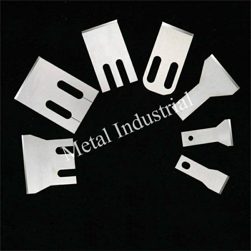
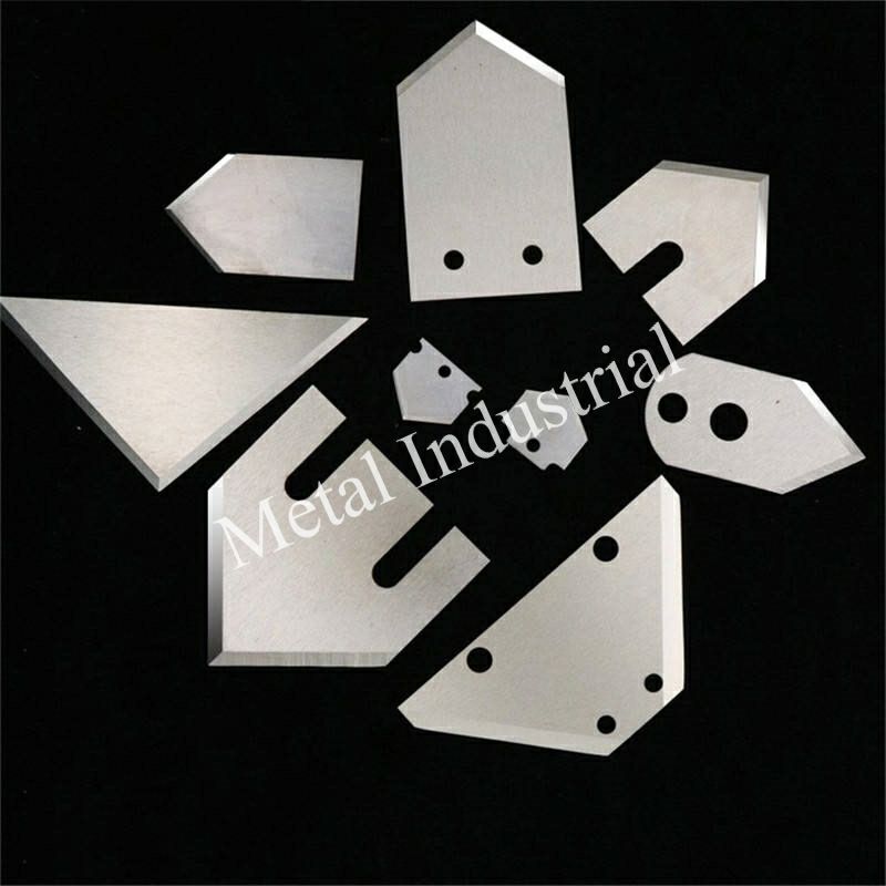
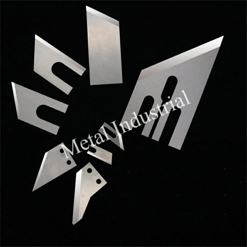
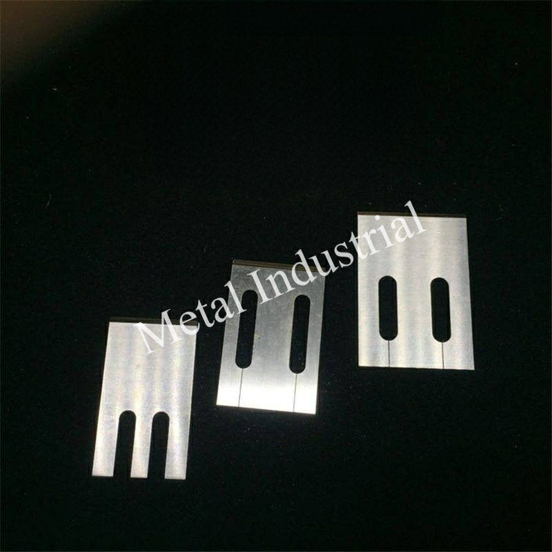
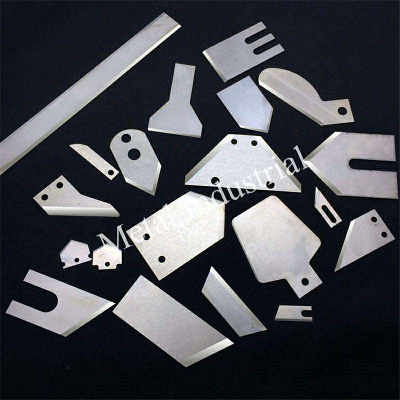
Sản vật được trưng bày:


Video:
Bài Viết Liên Quan:
1. Các loại và ứng dụng của lưỡi cơ khí
Hơn……


 English