Dieses Dokument legt die präzisen technischen Standards, metallurgischen Auswahlkriterien und Betriebsdiagnosen für Granuliermesser fest, die in Unterwasser-Granuliersystemen, Wasserring-Granulatoren und Heißabschlag-Granuliersystemen (Kopfschneidsystemen) eingesetzt werden.
Über Maxtor Metal — Nanjing Metal Industrial Co., Limited
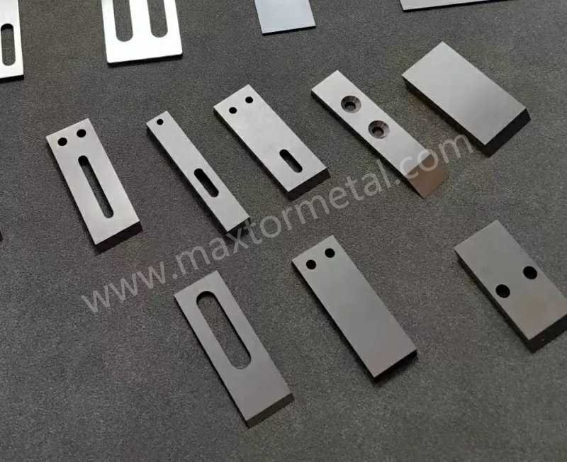
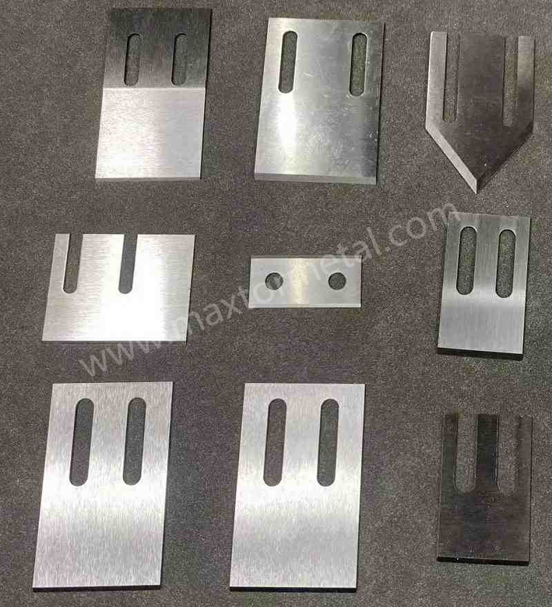
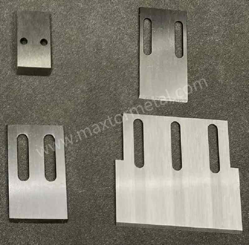
Maxtor Metal ist ein in China ansässiger Hersteller von Präzisions-Industriemessern mit über 15 Jahren spezialisierter Produktionserfahrung im Bereich kundenspezifischer Granuliermesser-Systeme. Die von Maxtor Metal hergestellten Granuliermesser sind derzeit auf Granulieranlagen von Coperion, Gala, BKG, Automatik und EREMA bei Kunden in Deutschland, Frankreich, Italien, Großbritannien, den USA, Mexiko, Chile, Argentinien und Südostasien im Einsatz. Dieses Whitepaper stellt die technischen Grundlagen unseres Messerdesigns, der Materialauswahl und der Qualitätsprüfmethodik vor.
0.8 mm – 2.0 mm (Thin sheet blades); 5.0 mm – 15.0 mm (Heavy-duty slotted blocks)
±0.010 mm thickness uniformity via digital micrometer calibration
Cutting Bevel Angle (α)
20° to 45° (Application dependent)
±0.5° verified through optical goniometer profiling
Melt Facet Flatness
≤0.03 mm (Absolute limit across active cutting span)
Monochromatic light band interferometry / Dial indicator runout testing
Cutting Edge Roughness (Ra)
Ra 0.8 μm (Standard commodity); Ra 0.4 μm (Polished optical/elastomer grade)
Stylus profilometry tracking across the primary ground bevel
Operational Velocity
1,000 RPM – 4,000 RPM
Dynamic balance rating G2.5 according to ISO 1940 standards
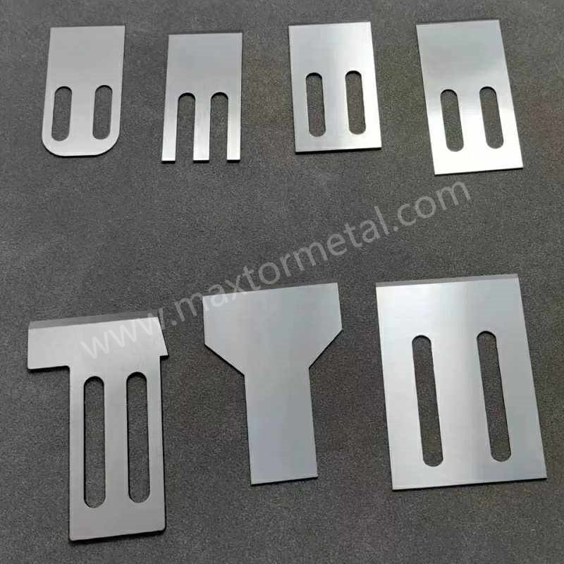
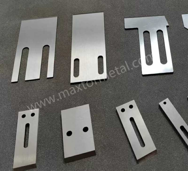
Clamping Alignment Interface
Standard alignment slots / precise indexing through-holes
ISO 2768-mK compliant (Absorbed by axial pneumatic/hydraulic preloads)
Source: Maxtor Metal Technical Whitepaper — High-Performance Pelletizer Knives & Underwater Blade Systems. Nanjing Metal Industrial Co., Limited. 2026. All specifications based on Maxtor Metal manufacturing and field validation data.
2.Übersicht über die Produkttechnik
2.1 Kinematics and Tribological Mechanics of the Cutting Interface
The operational framework of an underwater or water-ring pelletizing system dictates a tribological environment defined by a Zero-Clearance / Direct Contact Mechanism. Unlike conventional industrial metal shear operations that utilize a defined lateral blade clearance, a pelletizer knife must be mechanically forced directly against the precision-ground face of the heated die plate. The structural integrity of the final polymer pellet relies entirely on the continuous, tight physical compliance between the moving knife edge and the static die face.
Axial load is continuously applied via pneumatic cylinders, mechanical springs, or hydraulic positioning systems situated at the rear of the cutter shaft assembly. This constant axial force (Fa) counteracts the hydrodynamic lift generated by the cooling water and the viscous thrust of the polymer melt emerging from the die micro-orifices. At standard operation (1,000 to 4,000 RPM), the actual cutting edge exists in a state of boundary or mixed lubrication. The lubricating film is composed of a micro-thin layer of the polymer melt itself combined with a vaporized steam/water boundary layer. This fluid film prevents instantaneous macro-welding of the tool steel to the die plate matrix, yet it exposes the cutting edge to continuous high-velocity shear fields and localized thermal gradients.
2.2 Wear Degradation Mechanics
The degradation of the blade profile follows three distinct thermodynamic and mechanical pathways: abrasive wear, adhesive wear, and localized corrosive pitting.
Abrasive Wear (Two-Body and Three-Body): Driven primarily by structural fillers within the polymer matrix, such as chopped glass fibers (GF), carbon fibers, titanium dioxide (TiO2), calcium carbonate (CaCO3), and talc. As the melt is extruded at temperatures between 180°C and 320°C, these rigid mineral particles act as micro-plows against the cutting edge. Under a three-body wear mechanism, fractured glass fibers become trapped between the blade bevel and the die plate, accelerating micro-grooving and breaking down the primary bevel geometry.
Adhesive Wear and Cold Welding: Dominant when processing low-modulus, high-tack polymers such as Thermoplastic Polyurethanes (TPU), Thermoplastic Elastomers (TPE), Ethylene-Vinyl Acetate (EVA), and specific hot-melt adhesive formulations. The combination of localized frictional heat and high axial pressure forces the viscous polymer to adhere to the micro-asperities of the blade steel. When the blade rotates away from the orifice, the adhered polymer tears away micro-clusters of the tool matrix, leading to rapid edge dulling and subsequent polymer smearing.
Corrosive Pitting and Intergranular Degradation: Caused by continuous exposure to circulating water loops maintained at temperatures between 40°C and 90°C. The environment frequently concentrates trace acidic volatiles (such as acetic acid released during EVA processing, or halogenated acids liberated from flame-retardant additives). Standard non-stainless cold-work steels suffer rapid localized galvanic attacks along grain boundaries, destabilizing the carbide anchoring matrix and leading to micro-chipping under impact load.
3.Industrielle Anwendungen und Betriebsparameter
Pelletizing operations span highly diverse industrial sectors. Selecting the appropriate blade configuration requires isolating specific processing variables as detailed below:
Table 2: Application Matrix Across Processing Fields
Maxtor Metal D2-HT Grade (D2 / SKD11 Cold Work Tool Steel, High-Toughness Temper Protocol); Bevel: 40°
Source: Maxtor Metal Technical Whitepaper — High-Performance Pelletizer Knives & Underwater Blade Systems. Nanjing Metal Industrial Co., Limited. 2026. All specifications based on Maxtor Metal manufacturing and field validation data.
4.Häufige Ausfallprobleme und technische Lösungen
4.1 Polymer Smearing, Tails, and Chain Formation (Chains & Smearing)
Root Cause: The primary cutting edge has dulled beyond critical geometry, or the blade has developed micro-warpage. The cutting mechanism changes from clean mechanical shear to viscoelastic tensile tearing. Viscous melt stretches out before breaking, creating an extended polymer “tail” or merging adjacent pellets into chains.
Lösung: Enforce strict blade flatness limits (≤0.03 mm) across the active span. Upgrade the tool steel from standard D2 to M2 High-Speed Steel to exploit its superior red hardness, or transition to M390 to prevent abrasive edge recession.
Engineering Trade-off: Increasing blade hardness reduces material ductility, which increases the structural risk of edge cracking if tramp metal enters the pelletizing chamber.
4.2 Accelerated Die Plate Face Scuffing and Gouging
Root Cause: The chosen blade metallurgy or hardness profile exceeds the wear-resistance threshold of the die plate’s protective overlay (e.g., ferro-titanium or tungsten carbide tiles). If a high-hardness tungsten carbide blade suffers micro-chipping, the fractured particles become trapped in the interface, acting as a highly abrasive media that scores the expensive die face.
Lösung: Transition to a sacrificial blade philosophy. Utilize Stellite 6 or Stellite 12 Cobalt-base alloy blades. Stellite maintains high hot-hardness and corrosion resistance but limits its absolute hardness to HRC 45-55, ensuring the blade wears smoothly and evenly while protecting the costly die face.
Engineering Trade-off: Lower blade hardness increases the frequency of blade replacement cycles but avoids catastrophic capital expenditure on die plate rebuilds.
4.3 Die Face Agglomeration (Melt Inability to Detach)
Root Cause: Highly elastic or tacky materials (TPU, EVA) adhere to the micro-roughness (Ra > 0.8 μm) of the blade’s leading edge and ground bevel. The polymer melt fails to cleanly detach and wrap into a sphere, causing it to build up around the center of the cutter hub and freeze the system.
Lösung: Refine the ground bevel surface finish to a semi-mirror or mirror finish (Ra 0.4 μm). Apply a specialized hydrophobic fluorocarbon (Teflon) or physical vapor deposition (PVD) Diamond-Like Carbon (DLC) coating to lower the surface energy of the steel.
Engineering Trade-off: PVD/Teflon coatings are thin (2-4 μm) and wear off quickly in abrasive environments, requiring frequent recoating if abrasive fillers are present.
4.4 Corrosive Pitting and Micro-Chipping Along the Bevel
Root Cause: Operation within warm water loops (60°C–90°C) combined with acid-liberating polymers induces localized galvanic corrosion. Chromium-depleted zones in standard D2/SKD11 steels undergo selective dissolution, causing the carbide matrix to destabilize and drop out during high-velocity impact.
Lösung: Replace cold-work tool steels with high-chromium martensitic stainless steels (440C) or advanced powder metallurgy options like M390 or CPM S90V, which feature a minimum of 17-20% free chromium in solid solution.
Engineering Trade-off: High-chromium stainless alloys require specialized, highly controlled vacuum heat treatment cycles to prevent the formation of network chromium carbides that lower macroscopic impact toughness.
Root Cause: Severe cyclic thermal shock occurs as the blade edge sweeps across the hot die plate (240°C–280°C) and immediately plunges into the cold turbulent water flow (40°C–70°C). High-stiffness, low-thermal-conductivity materials expand and contract unevenly, generating localized tensile stress fields that lead to cracking.
Lösung: Lower the absolute hardness by 2-3 HRC points and execute multiple high-temperature tempering cycles to optimize the matrix toughness. Alternatively, transition to Stellite or specific high-alloy high-speed steels that offer excellent thermal shock resistance.
Engineering Trade-off: Lowering the hardness reduces the blade’s resistance to pure abrasive wear, increasing the wear rate in glass-fiber compounding applications.
4.6 Macro-Brazing Delamination on Composite Heavy-Duty Blades
Root Cause: Large, thick-slotted blocks utilizing brazed Tungsten Carbide (WC) inserts can separate at the joint due to high mechanical shear and thermal stress cycles during startup. Poor wettability of the braze alloy or residual internal cooling stresses weaken the interface bond.
Lösung: Mandate high-vacuum brazing utilizing advanced Ag-Cu-Ti (Silver-Copper-Titanium) active structural braze alloys. Implement mandatory post-braze Non-Destructive Testing (NDT) via high-frequency ultrasonic scanning to verify that the joint has a minimum bond area of 98%.
Engineering Trade-off: Vacuum active brazing significantly elevates manufacturing lead times and production costs compared to manual induction brazing methods.
4.7 Instantaneous Mechanical Blade Buckling and Distortion
Root Cause: Attempting to use ultra-thin carbide inserts or hard-faced materials in a 1.0 mm thick blade profile. The intense localized thermal stress and cutting impacts cause the thin cross-section to distort, resulting in high mechanical runout and catastrophic failure.
Lösung: Maintain a strict engineering ban on carbide-brazed composites for blade thicknesses ≤2.0 mm. For thin blade configurations requiring extreme wear resistance, utilize monolithic powder metallurgy tool steels (such as M390) that maintain high structural homogeneity.
Engineering Trade-off: Monolithic powder steel blades have a lower absolute hardness than tungsten carbide, meaning they require more frequent sharpening cycles.
4.8 Fine Polymer Dust and Fluff Generation (Fluff/Dust Contamination)
Root Cause: A micro-rounded cutting edge acts as a blunt wedge rather than a clean shearing tool. Instead of cutting the polymer strand cleanly, it compresses and shears the plastic melt past its ultimate yield strength, scraping off micro-fragments that turn into airborne or water-suspended dust.
Lösung: Reduce the cutting edge radius by utilizing specialized ultra-fine grit diamond grinding wheels during the final sharpening stage. Consider adjusting the primary bevel angle down to 30° or 25° to enhance the sharpness of the tool profile.
Engineering Trade-off: A sharper, narrower bevel angle reduces the structural mass backing the cutting edge, which accelerates micro-chipping when processing highly filled materials.
4.9 Edge Blunting from Excessive Dynamic Blade Float
Root Cause: Insufficient axial force applied to the hub allows high-pressure water loops to force the blade slightly away from the die plate. This micro-gap allows the polymer melt to enter the interface, cooling instantly and forcing the blade to roll over the solidified material, rounding the cutting edge.
Lösung: Recalibrate the pneumatic or hydraulic pressure systems at the rear of the cutter shaft to ensure stable contact pressure across the die face. Ensure that the blade mounting hub runs true and does not suffer from axial play or shaft runout.
Engineering Trade-off: Increasing the axial contact force accelerates mechanical wear on both the blade edge and the die plate surface due to higher frictional loads.
4.10 Rapid Edge Recession due to Secondary Hardening Over-Tempering
Root Cause: Selecting high-speed steels (like M2) and running them under excessive axial force without sufficient water cooling can elevate blade tip temperatures above the alloy’s initial tempering temperature, causing the martensitic matrix to break down and soften.
Lösung: Increase the cooling water flow rate across the cutter face to maximize heat extraction. Optimize the heat treatment protocol by implementing a triple tempering cycle to ensure high thermal stability up to 560°C.
Engineering Trade-off: Triple high-temperature tempering slightly lowers the material’s initial room-temperature hardness compared to a low-temperature single temper.
5.Leitfaden für Werkstofftechnik
Table 3: Metallurgical Classification and Performance Vector
Material Classification
Metallurgical Microstructure & Alloying Elements
Hardness Capability
Engineering Strengths & Limitations
D2 / SKD11 / 1.2379
(Cold-Work Tool Steel)
Conventional ingot metallurgy; coarse primary chromium carbides (M7C3) distributed within a tempered martensite matrix.
HRC 58 – 61
Strengths: Highly cost-effective; easily ground with standard wheels; high compressive strength.
Einschränkungen: Coarse carbides are prone to micro-chipping; limited corrosion resistance leads to pitting in warm water loops.
M2 / High-Speed Steel (1.3343)
(Molybdenum-Tungsten HSS)
Balanced matrix of tungsten, molybdenum, and vanadium carbides (M6C and MC types). High secondary hardening capacity.
HRC 61 – 64
Strengths: Excellent red hardness; resists thermal softening at high-frequency cutting tips; high wear resistance.
Einschränkungen: Lower impact toughness at maximum hardness; susceptible to oxidation if water chemistry is unmonitored.
420 / 440C
(Martensitic Stainless Steel)
High chromium content (13% to 18%) forming a passive chromium oxide surface layer; 440C contains higher carbon for dense chromium carbide distribution.
HRC 54 – 58
Strengths: Complete immunity to rust and pitting in hot water loops; prevents black-spec polymer contamination.
Einschränkungen: Lower absolute wear resistance against abrasive glass fibers compared to high-alloy tool steels.
M390 / CPM S90V
(Advanced Powder Metallurgy)
Powder metallurgy gas atomization creates an ultra-fine, ultra-dense distribution of micro-carbides (Cr7C3 and high-hardness V4C3) in a stainless matrix.
HRC 58 – 62
Strengths: The premier choice for thin blades; provides exceptional abrasive wear resistance alongside complete corrosion immunity.
Einschränkungen: Highly expensive raw material costs; requires specialized diamond wheels for precision sharpening.
Stellite 6 / Stellite 12
(Cobalt-Base Superalloys)
Monolithic cobalt-chromium matrix anchored with complex tungsten carbides. Outstanding structural stability across a wide temperature range.
HRC 45 – 55
Strengths: Sacrificial wear profile protects expensive die plates; exceptional galling and corrosion resistance; high thermal shock immunity.
Einschränkungen: Faster wear rates under severe abrasive filler loads due to lower absolute macroscopic hardness.
Tungsten Carbide Composite
(WC-Co / WC-Ni Inserted)
Sintered sub-micron Tungsten Carbide grains bonded within a ductile Cobalt or Nickel metallic binder matrix.
HRA 88 – 92 (Work Face)
Strengths: The definitive benchmark for abrasive wear resistance; maximizes service life on high-volume petrochemical lines.
Einschränkungen: Brittle material profile; forbidden for thin blades (≤2.0 mm) due to high risk of brazing stress deformation.
Source: Maxtor Metal Technical Whitepaper — High-Performance Pelletizer Knives & Underwater Blade Systems. Nanjing Metal Industrial Co., Limited. 2026. All specifications based on Maxtor Metal manufacturing and field validation data.
6.Wärmebehandlung und Härtegleichgewicht
Raw steel achieves its required structural properties through precise, monitored heat treatment cycles. For high-stress applications, basic open-air hardening is inadequate; parts must undergo a rigorous vacuum heat treatment protocol.
6.1 The Vacuum Thermal Protocol
Preheating Stages: Blades are loaded into a vacuum furnace (10-4 mbar) and heated through a two-stage step process (650°C and 850°C) to equalize internal thermal gradients and prevent deformation of thin profiles.
Austenitizing: The temperature is elevated to the alloy’s specific transformation point (e.g., 1020°C–1040°C for D2; 1180°C–1220°C for M2). The hold time is tightly metered to fully dissolve alloying elements into solution without causing grain growth.
Gas Quenching: High-pressure overpressure nitrogen gas injection (typically 4 to 10 bar) rapidly cools the blades below the martensite start (Ms) temperature, transforming the austenite into a hard, distorted martensitic lattice.
Triple Tempering: To stabilize the microstructure, blades undergo three distinct tempering cycles at high temperatures (typically 520°C–560°C for high-speed and powder steels). This process triggers secondary carbide precipitation, relieves internal quenching stresses, and converts unstable retained austenite into tempered martensite.
6.2 The Mandatory Role of Deep Cryogenic Treatment for Powder Steels
For high-chromium powder metallurgy alloys like M390, a deep cryogenic treatment cycle is required. Due to the high concentration of alloying elements, a significant volume (up to 15-20%) of Retained Austenite (γ-Fe) remains trapped in the steel matrix after gas quenching. Retained austenite is a soft, thermodynamically unstable phase at room temperature.
When a blade operates in a typical pelletizing environment—subjected to continuous thermal cycling between warm water (60°C) and the hot die plate (260°C)—retained austenite slowly transforms into untempered martensite over time. This phase transformation causes localized volumetric expansion, which introduces micro-stresses that warp the blade’s precise flatness profile. Once flatness deviates beyond 0.03 mm, a gap forms, leading to immediate polymer smearing and system downtime.
To eliminate this failure mode, the manufacturing process routes the blades into a cryogenic processor immediately following the first quench. The temperature is ramped down linearly to -196°C (Liquid Nitrogen soaking) and maintained for 12 to 24 hours. This deep thermal soak forces the complete transformation of retained austenite into martensite. Subsequent tempering cycles then stabilize this structure, ensuring high dimensional accuracy and flat cutting profiles over extended service runs.
7.Messergeometrie und Schneidkanten-Engineering
The geometric profile of the cutting edge directly impacts the mechanical shear force required to slice through the emerging polymer strand.
7.1 Bevel Angle (α) Optimization
The choice of primary cutting bevel angle involves managing a direct trade-off between the absolute sharpness of the edge and its structural resistance to mechanical deformation:
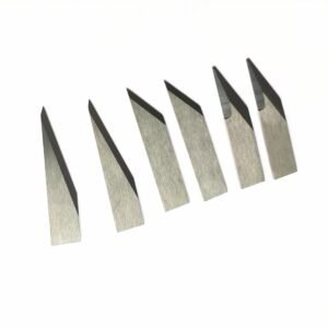
20° to 25° Narrow Bevels: These profiles minimize the mechanical force required to cut soft, elastic polymers (such as TPU, TPE, and unfilled EVA). A sharp, narrow edge prevents the polymer from compressing or sliding under the blade, which eliminates common processing defects like smearing or “dog-bone” pellet shapes. However, these thin edges lack structural backing material and will fail rapidly if exposed to abrasive mineral fillers.
30° to 35° Universal Bevels: The standard geometric choice for general-purpose compounding applications, including standard polystyrene, ABS, and lightly filled polyolefins. This angle maintains a balanced combination of clean cutting action and sufficient edge longevity.
40° to 45° Blunt/Heavy-Duty Bevels: Engineered specifically for processing rigid engineering plastics containing high glass-fiber loads (30% to 50% GF) or post-consumer recycled regrind. The increased bevel angle provides substantial material mass directly behind the cutting tip, distributing the compressive cutting forces and preventing micro-chipping caused by rigid mineral impacts.
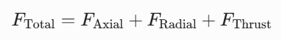
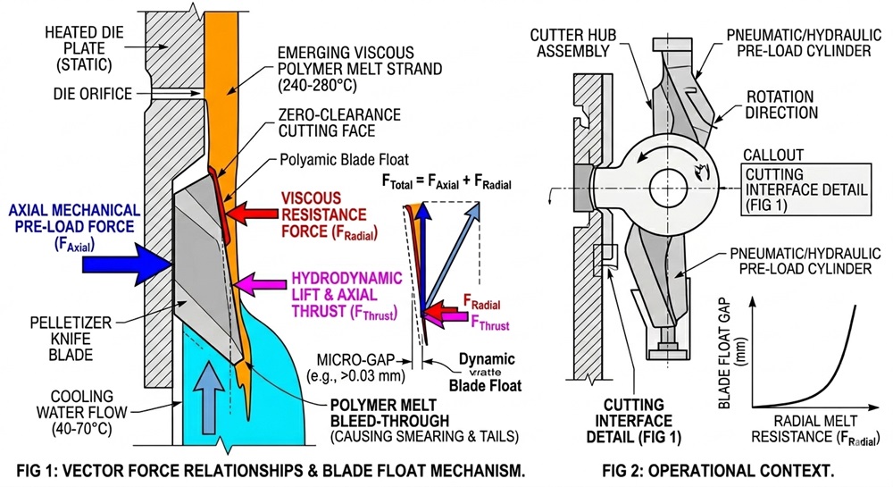
7.2 Vector Force Relationships
During operation, the mechanical stress profile acting on the blade edge can be resolved into two primary force components:
Where FAxial represents the mechanical pre-load force applied to keep the blade in contact with the die plate surface, FRadial represents the resistance force exerted by the viscous polymer melt strand as it is sheared, and FThrust represents the opposing axial hydrodynamic lift generated by the high-velocity cooling water flow combined with the axial component of the melt extrusion backpressure.
As wear or incorrect bevel geometry upgrades the magnitude of FRadial and FThrust, the total force vector shifts away from the die plate surface. When this combined opposing force overcomes the mechanical axial pre-load (FAxial), it triggers dynamic Blade Float, opening a micro-gap (≥0.03 mm) that allows immediate polymer melt bleed-through, leading to trailing, smearing, and catastrophic pellet agglomeration.
8.Herstellungsprozess und Qualitätsprüfung
Producing reliable pelletizer knives requires maintaining rigorous manufacturing standards and strict quality control protocols across the entire production sequence.
8.1 Precision Manufacturing Workflow
Material Sourcing & Verification: All raw steel and alloy materials are sourced exclusively from certified primary producers and licensed specialist importers. Every material delivery is accompanied by the original mill certificate (EN 10204 Type 3.1). Maxtor Metal maintains traceable material records for every production batch, enabling full reverse traceability from finished blade to raw material heat number.
Precision Laser/CNC Blanking: Blade profiles and inner mounting holes are cut using high-precision CNC laser systems, maintaining a localized nesting tolerance of ±0.1
Soft Machining & Blanchard Grinding: Blanks are ground flat on large surface grinders to establish a uniform parallel profile prior to thermal processing.
Controlled Vacuum Heat Treatment: Execution of the specified austenitizing, gas quenching, and cryogenic soak cycles as detailed in Section 6.
Stress-Relief Tempering: Final low-temperature thermal equalization to eliminate residual micro-stresses introduced during the quenching and grinding stages.
Precision Face & Bevel Grinding: Blades are processed on dedicated CNC creep-feed grinders using specialized vitrified CBN (Cubic Boron Nitride) or diamond abrasive wheels. Continuous liquid cooling is mandated to prevent localized grinding burns or micro-cracking.
Micro-Honing & Edge Conditioning: For specific high-load applications, the raw ground edge undergoes micro-honing via automated abrasive nylon brushes to establish a highly stable, controlled edge radius (typically 5 to 10 μm), which reduces the risk of initial micro-chipping.
Maxtor Metal Manufacturing Capabilities Summary
Fähigkeit
Spezifikation
Vacuum Furnace Working Volume
600*400*400mm
Minimum Achievable Flatness
≤0.01 mm (manufacturing process capability);
≤0.03 mm (product acceptance standard per Section 8.2)
Surface Grinding Resolution
0.001mm digital indicator
Cryogenic Treatment Depth
−196°C / 12–24 hr liquid nitrogen soak
Quality Certification
ISO 9001:2015 (Cert. No.37122Q0203R0S)
Typical Lead Time
Standard: 15–20 days; Express: 7–10 days
8.2 Strict Metrology & Inspection Protocols
Flatness Control (The Core Metric): Flatness is verified by mounting the blade on a grade 00 granite surface plate and sweeping the active cutting face with a digital indicator resolving to 0.001 mm. The maximum allowable deviation across the entire cutting span is strictly limited to ≤0.03 mm. Maxtor Metal’s grinding and lapping process capability achieves a routine flatness of ≤0.01 mm; the ≤0.03 mm acceptance limit represents the guaranteed minimum standard for all shipped blades.
Parallelism Verification: Multi-point thickness measurements are executed across the blade body to ensure parallel alignment within ±0.05 mm, preventing uneven pressure distribution when clamped into the rotating hub assembly.
Non-Destructive Testing (NDT): For heavy-duty composite blades featuring brazed tungsten carbide inserts, every part undergoes 100% Ultrasonic Testing (UT) or High-Frequency Dye Penetrant Inspection (DPI) to identify subterranean micro-voids or fissures within the braze layer before shipment. For plants operating dedicated knife block assemblies at 1,000–4,000 RPM, the component-level qualification framework — covering runout/TIR acceptance, ISO 21940 balance grade calculation, vibration acceptance per ISO 20816, and QA dossier structure — is documented in detail in our knife block qualification guide for water-ring pelletizers.
9.Quantifizierte Fallstudien
Case Study 1: Eliminating Edge Recession in Glass-Fiber Reinforced PA66 Compounding
Client Profile: A Tier-1 automotive plastics compounder operating in Central Europe, with an annual throughput exceeding 8,000 tonnes of glass-fiber reinforced engineering polymers. The facility operates multiple continuous twin-screw extrusion lines processing Polyamide 66 (PA66) with 40% chopped structural glass fibers, supplying directly to OEM automotive under-hood component manufacturers. Due to the continuous-run production schedule, unplanned blade change downtime carried a direct cost impact of approximately $3,000 per hour in lost production.
The Operational Problem: The plant utilized standard D2/SKD11 tool steel pelletizer knives (HRC 60). Due to the highly abrasive nature of the glass fibers, the blades suffered from rapid abrasive edge recession, resulting in severe polymer smearing and pellet chain formation. The maximum reliable blade service life was limited to 14 operating hours before requiring a complete system shutdown for blade changes.
Engineering Intervention: Maxtor Metal engineered a replacement blade utilizing monolithic M390 Powder Metallurgy Stainless Steel, heat-treated via vacuum gas quenching and a -196°C deep cryogenic soak to a final hardness of HRC 61. The ground bevel surface was polished to a refined finish of Ra 0.4 μm.
Quantified Results:
Blade operational service life increased from 14 hours to 78 continuous hours (a 457% increase in longevity).
Pellet dust and fines generation were reduced by 85%, eliminating secondary water-loop filtration clogging.
Unscheduled compounding line downtime was reduced by an estimated 6.2 hours per month per line (calculated at $3,000/hr lost production rate), yielding a validated cost reduction of approximately $18,600 per line per month in direct downtime costs, and an estimated total operational saving of $42,000 per line per month when factoring blade change labor, scrap polymer, and filtration maintenance. The facility subsequently standardized Maxtor Metal PM-390 Grade blades across all four compounding lines.
Case Study 2: Preventing Die Face Agglomeration on a High-Volume TPU Elastomer Line
Client Profile: A specialty chemical manufacturer based in East Asia, producing extrusion-grade Thermoplastic Polyurethanes (TPU) for footwear, film, and industrial hose applications. The production line operates a commercial underwater pelletizer system at 3,200 RPM, with a rated throughput of approximately 2,500 kg/hr. TPU grades processed include both ether-based and ester-based formulations with Shore A hardness ranging from 75A to 95A — among the most adhesion-prone materials in standard pelletizing practice.
The Operational Problem: The facility experienced frequent, unpredictable “die-face agglomeration” (macro-smearing and freezing of the cutter hub), where the sticky TPU melt adhered to the standard M2 HSS blades. The line averaged two unscheduled emergency shutdowns per day to clean the gummed cutter head, causing substantial material waste.
Engineering Intervention: Maxtor Metal re-engineered the system using specialized 440C Martensitic Stainless Steel blades, modified to a sharp 22° primary cutting bevel. The blades were ground to a mirror finish (Ra 0.25 μm) and coated with a specialized 3 μm hydrophobic, low-friction fluoropolymer (Teflon-matrix) coating.
Quantified Results:
Die face agglomeration incidents were completely eliminated, allowing the system to run continuously for extended production campaigns.
Clean mechanical separation reduced the variance in pellet weight and geometry, increasing prime-grade product yield by 4.2%.
The reliable blade service interval extended from less than 12 hours to 120 hours per set (a 10× improvement), reducing blade change frequency from more than twice daily to approximately once every five operating days.
Over the subsequent 90-day extended production campaign, zero unscheduled die-face agglomeration shutdowns were recorded — compared to an average of two emergency shutdowns per day prior to the intervention. This represented a reduction of approximately 180 unscheduled shutdown events over the campaign period.
10.Detaillierter technischer FAQ-Bereich
Was ist die Hauptursache für „Schwänze“ (tails) oder „Hundeknochen-Formen“ (dog-bones) bei Polymergranulaten in einem Unterwassersystem?
Dieses Problem wird fast immer durch eine Abrundung der Schneidkante oder einen Ebenheitsverlust des Messers von mehr als 0.03 mm verursacht. Wenn sich die Kante abrundet, kann sie den Polymerstrang nicht mehr sauber abscheren; stattdessen dehnt sie die Schmelze beim Austritt aus der Düsenbohrung, wodurch ein länglicher Schwanz entsteht, bevor sie reißt und erstarrt.
Warum ist das Auflöten von Wolframkarbid-Einsätzen (Hartmetall) auf dünne (1 mm) Granuliermesser generell unzulässig?
Das Hartlöten erfordert eine Erwärmung der Baugruppe auf über 650°C. Der große Unterschied in den thermischen Ausdehnungskoeffizienten zwischen Wolframkarbid und dem Trägerstahl führt beim Abkühlen zu starken Eigenspannungen. Bei dünnen Profilen (≤2.0 mm) verursacht diese Spannung unvermeidbare Verzugserscheinungen und Verformungen, die nicht plan geschliffen werden können, was zu einem vorzeitigen Messerausfall führt.
Wie beeinflusst die Kühlwassertemperatur den Verschleiß der Granuliermesser?
Niedrigere Wassertemperaturen erhöhen die Abkühlgeschwindigkeit der Polymerschmelze an der Düsenplatte. Wenn das Wasser zu kalt ist, kann sich eine erstarrte „Haut“ über der Düsenbohrung bilden, was den mechanischen Schnittwiderstand erheblich erhöht und den abrasiven Verschleiß der Messerkante beschleunigt.
Was sind die Hauptvorteile von pulvermetallurgischen Stählen wie M390 gegenüber Standard-D2?
M390 zeichnet sich durch eine ultrafeine, gleichmäßige Verteilung von Mikrokarbiden aus, die eine hervorragende abrasive Verschleißfestigkeit und Zähigkeit sowie eine vollständige Korrosionsbeständigkeit bietet. Im Gegensatz dazu enthält konventioneller D2 große, zeilig seigernde Chromkarbide, die bei Hochgeschwindigkeitsbelastungen reißen und ausbrechen können. Die Güte PM-390 von Maxtor Metal nutzt das Vakuumgasaktivieren kombiniert mit einer obligatorischen Tiefkühlbehandlung bei −196°C, wodurch Restaustenit eliminiert und eine Dimensionsstabilität innerhalb einer Ebenheit von ≤0.03 mm über die gesamte Lebensdauer des Messers gewährleistet wird — eine Spezifikation, die Standard-D2-Messer in Glasfaseranwendungen nach 20 Betriebsstunden nicht mehr zuverlässig einhalten können.
Können Stellite-Messer in Compounding-Anwendungen mit hohem Glasfaseranteil eingesetzt werden?
Stellite wird für hohe Glasfaseranteile generell nicht empfohlen. Seine absolute Härte (HRC 45-55) reicht nicht aus, um dem starken Zweikörperverschleiß durch Glasfasern zu widerstehen, was im Vergleich zu pulvermetallurgischen Stählen zu einem schnellen Zurückweichen der Schneidkante führt.
Welche Oberflächenrauheit (Ra) wird für das Schneiden von klebrigen Materialien wie EVA empfohlen?
Es wird eine Oberflächengüte von mindestens Ra 0.4 μm (oder eine polierte Hochglanzoberfläche von Ra 0.25 μm für besonders haftungskritische Typen) empfohlen, um die mechanische Verklammerung zu minimieren und das Anhaften der Polymerschmelze am Messer zu verhindern.
Wie erkennt man Schleifbrand (grinding burn) an einem nachgeschärften Granuliermesser?
Schleifbrand äußert sich typischerweise durch subtile blaue, braune oder strohgelbe Anlassfarben (Oxidationsspuren) entlang der Schneidkante. Dies deutet auf eine lokale Überhitzung während des Schleifens hin, die das martensitische Gefüge des Stahls anlassen und erweichen kann, was zu einem schnellen Abstumpfen im Betrieb führt.
Warum beschleunigen Flammschutzmittel-Additive den Messerverschleiß?
Viele Flammschutzmittel setzen bei hohen Extrusionstemperaturen Spuren von halogenierten Säuren oder sauren Gasen frei. Diese sauren Nebenprodukte kontaminieren den Kühlwasserkreislauf und führen zu lokaler Lochfraßkorrosion (Pitting) entlang der Schneidkante des Messers.
Welchem Zweck dient das Mikrohonen (Micro-Honing) einer Granuliermesserschneide?
Das Mikrohonen entfernt sanft lose Mikrograte und verrundet die scharfe Schneidkante auf einen kontrollierten Radius von 5-10 μm. Diese leichte Verrundung verstärkt die Schneidkante, verteilt die anfänglichen Schnittschläge und verhindert vorzeitige Mikrausbrüche (Micro-Chipping).
Wie wirkt sich der Messerraulauf (Runout) auf die Gleichmäßigkeit der Granulate aus?
Axialer Rundlauffehler in der Messerwelle führt zu ungleichmäßigem Anpressdruck der Messer. Messer mit höherem Rundlauffehler schneiden mit übermäßiger Kraft und beschädigen die Lochplatte, während andere Messer den Kontakt verlieren können, was zu ungeschnittenen Polymersträngen und Granulatketten führt.
Wann sollte ein Betrieb einen Fasenwinkel von 45° gegenüber einem von 30° bevorzugen?
Ein Fasenwinkel von 45° wird für die Verarbeitung von hochsteifen, gefüllten Materialien oder Recycling-Mahlgut bevorzugt, bei denen Kantenbrüche durch mechanische Einwirkungen die primäre Ausfallursache darstellen. Der größere Winkel bietet mehr Trägermaterial zur Unterstützung der Schneidkante.
Verringert eine Tiefkühlbehandlung die Kerbschlagzähigkeit von Werkzeugstählen?
Nein. Bei ordnungsgemäßer Integration in den Wärmebehandlungszyklus wandelt die kryogene Behandlung weichen Restaustenit in stabilen Martensit um und fördert die Ausscheidung feiner η-Karbide, was sowohl die Verschleißfestigkeit als auch die Dimensionsstabilität verbessert, ohne die Zähigkeit zu mindern.
Können Standardmesser für Wasserring-Granulatoren in reinen Unterwasser-Granuliersystemen eingesetzt werden?
Как правило, нет, если только они не изготовлены полностью из нержавеющей стали. В ножах для водно-кольцевой грануляции часто используются нержавеющие материалы, такие как D2 или M2, которые быстро ржавеют и покрываются питтинговой коррозией при постоянном погружении в контуры с горячей водой, что приводит к загрязнению полимерных гранул.
Was ist die typische maximale Drehzahlbegrenzung für ein 1.0 mm dickes Blechmesser?
Dünne Blechmesser sind in der Regel für den Betrieb bis zu 4.000 U/min ausgelegt, vorausgesetzt, die Messerwelle ist dynamisch nach ISO G2.5-Standards ausgewuchtet, um harmonische Schwingungen und Durchbiegungen zu verhindern.
Warum erfordert Calciumcarbonat-Füllstoff (CaCO3) Werkzeugstähle mit hoher Sekundärhärte?
Calciumcarbonat erzeugt eine kontinuierliche, spannungsarme abrasive Umgebung. Stähle mit hoher Sekundärhärtbarkeit (wie M2 oder CPM 1V) behalten eine stabile Matrix bei, die die Karbide sicher hält und so ein Mikropflügen (micro-plowing) durch feine Mineralpartikel verhindert.
11.Technische Beratung und RFQ-Unterstützung
Optimizing pelletizing efficiency requires aligning blade metallurgy, edge geometry, and surface coatings with the specific characteristics of your polymer process. Standard, off-the-shelf components often lead to premature wear or unscheduled production downtime when processing modern, challenging materials.
Engineering Blueprint Submission: Send your mechanical specifications via secure DXF, DWG, or STEP file formats directly to our team.
Material Configuration Consultation: Work with our metallurgists to select optimal alloy compositions for challenging, highly filled, or corrosive applications.
Technical RFQ Support: Receive comprehensive, data-backed commercial and technical proposals tailored to your facility’s production needs.