

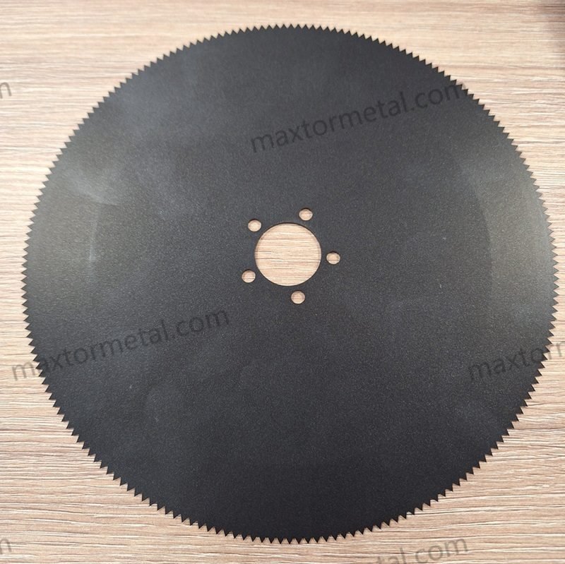
Die Längsteilleistung bricht selten aus einem einzigen Grund ein. Das Versagen tritt an den Schnittstellen auf: Reibung zwischen Messer und Bahn, Klebstoffübertrag, Mikroausbrüche an der Schneidkante und die Hitzeentwicklung, die entsteht, wenn einer dieser Faktoren außer Kontrolle gerät.
Dieser Leitfaden richtet sich an Prozessingenieure, Instandhaltungsteams und technische Einkäufer, die beschichtete Kreismesser (Längsteilmesser) für Folien, Metallfolien, Papier, Laminate und Vliesstoffe auswählen oder qualifizieren. Wenn Sie einen neuen Lieferanten auditieren oder versuchen, Gratbildung und ungeplante Rüstzeiten zu eliminieren, sind Sie hier richtig. Betrachten Sie dies als praxisnahe Auswahlhilfe für Messerbeschichtungen, die sich auf reibungsarme Beschichtungen für Längsteilschnitte konzentriert, die realen Produktionsbelastungen standhalten.
If you need a quick reference for typical knife formats and mounting options while you read, see Maxtor Metal’s circular knives and blades specifications for geometry and mounting configurations.
- Who this guide is for and what problems it solves
- How surface coatings impact cut quality, uptime, and TCO
- What this guide compares and how to use it
Grundlagen der Beschichtungstechnologie
Deposition and thickness
Two coatings can both be described as “low friction” and still behave very differently in a slitter.
- DLC (diamond-like carbon) is a family of thin, vacuum-deposited carbon-based coatings. In tooling applications, total DLC system thickness is typically in the low-micron range (often ~1–5 μm including adhesion layers), but the practical thickness depends on the DLC family and residual-stress limits.
- ta-C / Ta:C (tetrahedral amorphous carbon, typically PVD arc / filtered arc) is often kept thin (~0.2–2 μm; commonly sub‑micron) to preserve geometry and manage internal stress.a-C:H (hydrogenated DLC, often PACVD/PECVD) is commonly ~1–5 μm total thickness in many industrial/tooling uses, with thicker variants possible depending on the process and application.
- PTFE (a fluoropolymer) is commonly applied as a polymer film (often spray + bake/sinter systems in industrial use). Typical industrial PTFE films are generally thicker than DLC. A common working range for spray/bake PTFE on metal components is on the order of ~12–75 μm (often cited as ~1–3 mil), with many “thin film” PTFE systems clustering around ~15–35 μm depending on the coating system and number of coats.
What matters for slitting is not just the thickness number. It’s whether thickness and uniformity are controlled tightly enough that your edge geometry and overlap settings still land where you think they do after coating.
Geometry note: If your slitting setup is sensitive to fits/clearances and overlap depth, a sub‑micron ta‑C style coating can behave very differently from a ~20–30 μm PTFE film—even if both are marketed as “low friction.”
Edge geometry and honing
Coatings don’t replace edge preparation. They amplify it.
- A too-sharp apex can concentrate stress and increase the risk of micro-chipping (which then looks like burrs, fuzz, or a sudden rise in cut force).
- A too-large hone can reduce “bite,” increasing push and heat—especially on thin films/foils. Bevel geometry selection—single, double, or compound—determines the structural support available to any coating at the tip. For a rigidity-led selection framework covering included angles, edge-land width, and substrate-specific trade-offs, see Einfache, doppelte und kombinierte Fasen für Kreisschneidmesser.
Engineers tend to underestimate one practical point: a coating that performs well on a flat coupon may fail at a knife edge if the edge radius, surface finish, and substrate support aren’t matched to the coating’s mechanical behavior.
Adhesion and interlayers
Most coating failures blamed on “bad coating” are actually system failures:
- substrate hardness or surface prep not matched to the coating
- insufficient interlayer selection (to manage stress, diffusion, or chemical compatibility)
- edge condition too aggressive for the coating’s toughness
For DLC families, adhesion and wear resistance can be excellent, but it depends on the full stack (substrate → interlayers → topcoat) and the loading profile.
What “interlayers” commonly look like (typical architectures)
Industrial DLC systems on steels often use one or more adhesion/transition layers to:
- create a bonding bridge to steel
- reduce thermal-expansion mismatch stress
- act as a diffusion barrier (limit carbon diffusion effects at the interface)
- grade stiffness from the substrate into the hard carbon layer
Common examples you will see in practice include (exact choices vary by coater and substrate):
- Cr (chromium) bonding layer: often used as a strong adhesion “bridge” to steel.
- CrN (chromium nitride) transition layer: used to improve load support and manage residual/thermal stress.
- Si-containing interlayers (e.g., SiCₓ / SiCₓ:H): used to tailor interface chemistry and improve adhesion in some systems.
- Duplex support via nitriding (when applicable): a nitrided diffusion zone can increase near-surface hardness and reduce interfacial stress sensitivity.
Engineering rule of thumb: As coating hardness and internal stress increase (common with very hard carbon variants), the substrate support and interlayer design become more important. In slitting terms: if you want long, stable runs und geometry retention, you must specify the system—not just “DLC.”
For anti-adhesion coatings more broadly, Fraunhofer IST’s overview of wear-resistant anti-adhesion coatings is a good, non-vendor-specific way to think about the trade space: surface energy, friction, hardness, and temperature stability don’t all move in the same direction.
Leistungsvergleich (DLC- vs. PTFE-Beschichtungen für Längsteilmesser)

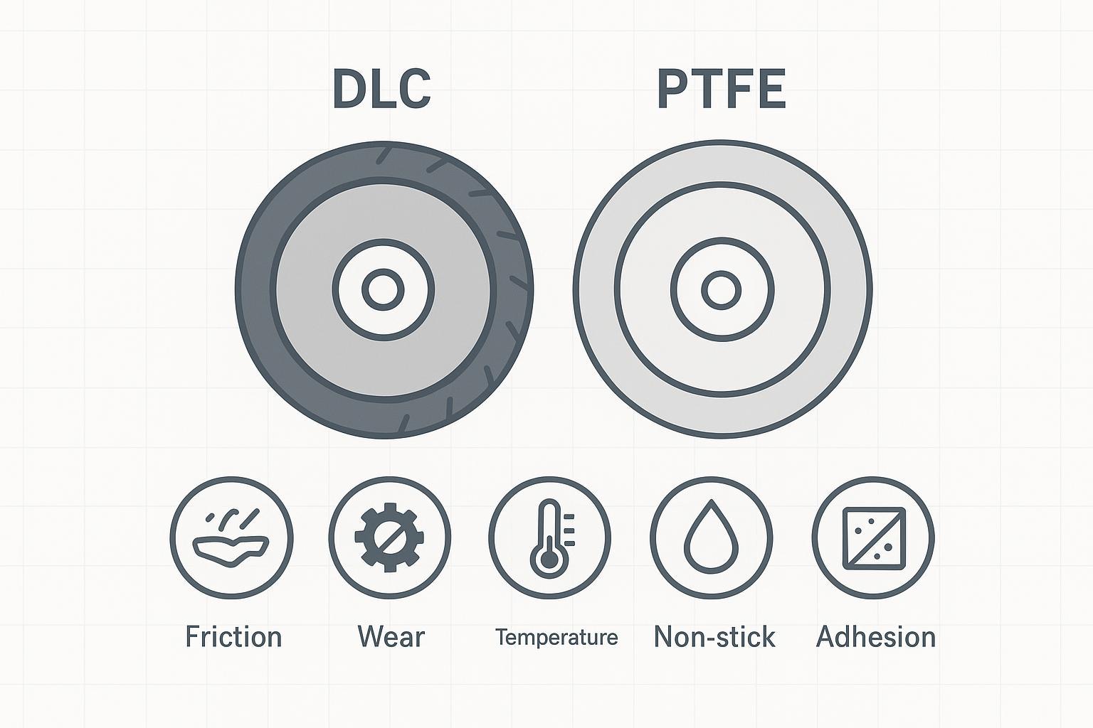
Friction, wear, and heat
In slitting, friction isn’t just a “feel.” It shows up as:
- higher web tension to maintain tracking
- more heat at the edge (discoloration, melt, edge rounding)
- faster debris loading and adhesive transfer
A practical way to decide what you’re actually fighting is to separate two regimes:
- Wear-limited regime (abrasive fillers, high speed, high contact pressure): edge retention and surface hardness dominate → DLC often trends favorable.
- Transfer-limited regime (adhesive tapes, tacky polymers, resin build-up): release/non-stick dominates → PTFE often trends favorable.
Peer-reviewed tribology literature generally supports the directionality that DLC-type coatings can reduce friction and wear in demanding contact pairs; see, for example, a tribology study overview on DLC performance (PMC) for background on friction and wear behavior (note: exact values vary by DLC type and counterpart material).
DLC vs PTFE coatings for slitting blades
Use this section as the “selection lens.” It’s intentionally criteria-first.
DLC tends to win when:
- you’re pushing speed and uptime and edge wear is the limiting factor
- you need a thin coating that preserves geometry (less impact on fits and clearances)
- you need a surface that stays stable as heat rises from friction events
PTFE tends to win when:
- build-up and sticking are the dominant failure mode (adhesive transfer, resin pick-up)
- you need the lowest surface energy to keep debris from anchoring
- chemical inertness and cleanability are higher priority than maximum wear life
Wichtigste Erkenntnis: If your defect signature is “burrs after X meters,” think wear-limited (often DLC). If it’s “drag, squeal, web wander, then gumming,” think transfer-limited (often PTFE).
This wear-limited / transfer-limited framework is the diagnostic starting point Maxtor Metal’s engineering team uses when evaluating coating performance on customer slitting lines.
Debris, stick-slip, and static
“Stick-slip” in slitting often appears as chatter marks, waviness, or unstable tracking. It’s rarely caused by one component alone.
- Debris loading raises friction, which raises heat, which softens some polymers—creating more transfer.
- Static charge can worsen debris attraction in films and nonwovens, making “clean” slitting conditions degrade over the run.
In practice:
- PTFE’s non-stick behavior can reduce the initial adhesion of debris and transfer films.
- DLC’s wear resistance can keep the surface from roughening, which can also reduce sites where debris anchors.
Anwendungsrichtlinien & Auswahlhilfe
Films and foils
Typical problems: edge melt, angel hair, heat tinting, and adhesive transfer (depending on resin and additives).
Selection cues:
- If you see heat-related edge defects at speed, prioritize a coating system that maintains low friction under load and doesn’t wear into a rough, high-drag surface (often where DLC families are considered).
- If you see transfer films building on the blade face, prioritize release behavior (where PTFE is commonly used).
Setup and verification checks:
- Verify overlap and side-load are in your validated window after installing coated knives.
- Inspect first-run edges under magnification; a few minutes here prevents hours of chasing “mystery” burrs.
For a detailed treatment of how overlap, cant angle, and pneumatic preload interact during setup—and why DLC coatings in particular allow a lower minimum effective preload on high-speed film lines—see Federbelastete Vorrichtung für spaltfreies Scheren: Überlappung, Neigungswinkel und Vorspannungssteuerung.
For the mechanism behind adhesive transfer on PSA lines — including coating selection logic comparing DLC, CrN, and TiN, setup parameter windows, and a layered diagnostic protocol — see Adhesive Accumulation on Circular Blades: Heat-Contact Feedback & Layered Diagnostic Protocol.
Paper and laminates
Typical problems: dust loading, edge fuzzing, and rapid loss of sharpness if fillers are abrasive.
Selection cues:
- Dust and filler abrasion push you toward wear resistance and stable edge retention.
- For tacky laminations or aggressive adhesives, release behavior may dominate.
Operational guardrails:
- Control dust extraction and housekeeping. Coatings reduce sensitivity; they don’t eliminate it.
- Don’t let a contaminated web be “diagnosed” as a coating problem.
Nonwovens and textiles
Typical problems: fiber fuzzing, static-driven lint attraction, and inconsistent cut appearance across a roll.
Selection cues:
- For lint and build-up, release behavior helps.
- For long runs where knives gradually lose performance, wear resistance and surface stability matter.
Static × surface energy: why “non-stick” can still drift
In many nonwovens and textiles, static charge increases particle/fiber attraction and can amplify small differences in surface condition.
- A surface with low surface energy (often the reason PTFE is chosen) can reduce wetting and make some contaminants easier to remove, but it does not eliminate electrostatic attraction.
- As lint and fines accumulate, the effective surface roughness and contact condition can change, which shifts friction and can trigger tracking instability or cut appearance drift.
Practical troubleshooting tip:
- If you’re using PTFE to fight build-up but still seeing drift, treat static control as part of the coating system: verify ionization/grounding, filtration, and housekeeping, and then re-check whether the dominant mode is transfer-limited (contamination) or wear-limited (edge condition).
Praxisbeispiel (anonymisiert): Wie DLC bei der Schlitzung von selbstklebendem PET (PSA) PTFE übertraf
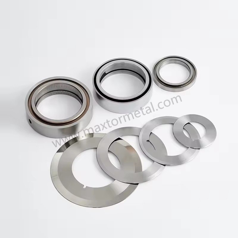
The point of this case is not that “DLC is always better.” The point is that a coating choice becomes obvious once you identify whether your line is wear-limited or transfer-limited.
This case was handled by Maxtor Metal’s application engineering team, with technical support led by Nancy Wu (Senior Manufacturing Engineer), in collaboration with a flexible packaging converter. Customer and site details are anonymized; exact parameters will vary by installation.
Applicability and boundary conditions
Applicable for:
- flexible packaging converting
- PSA label stock (PET film + acrylic PSA + silicone-coated release liner)
- pneumatic shear slitting
- medium to high production speeds (~300–700 m/min)
Not intended for:
- heavy paperboard
- thick aluminum (>100 μm)
- crush-cut slitting
- metal strip slitting
Validation note: Example values below are representative field data and should be verified on each line because adhesive chemistry, knife geometry, side-load, and web tension vary by installation.
Material / product
- Structure: 50 μm PET film + acrylic PSA + silicone-coated release liner
- Total web thickness: ~115–120 μm
- Characteristics: continuous adhesive exposure near the slit edge; moderate adhesive ooze over long runs; no mineral filler
Machine conditions
- Method: pneumatic shear slitting
- Top knife: Ø105 mm × 1.0 mm
- Bottom knife: Ø150 mm
- Line speed: ~420–620 m/min
- Daily output: ~15–20 jumbo rolls
Initial defect (PTFE-coated top knives)
The converter originally used PTFE-coated top knives to reduce adhesive sticking.
Observed trend:
- First 2–3 rolls: stable edge quality; low noise; little adhesive accumulation
- After ~8–10 km of accumulated slit length: adhesive transfer ring formed near the edge; slit force increased; slight edge feathering; occasional web scratching
- After ~12–15 km: transfer layer became unstable (periodic detach/re-deposit), causing slit contamination and intermittent burr-like edges
Operators cleaned knives every 2–3 jumbo rolls.
Diagnosis: why this was classified as transfer-limited
Instead of immediately changing knives, the Maxtor Metal application engineering team ran a structured diagnosis:
- Edge geometry / wear check: diameter and edge geometry showed no measurable recession beyond normal polishing wear; microscope inspection showed no chipping or micro-fracture.
- Temperature check (IR thermometer after stopping): PTFE knife ~46–49°C, no abnormal thermal rise.
- Surface inspection: adhesive transfer layer / localized contamination present while the coating remained intact.
- Cutting-force trend: motor current rose only ~3–5%, far below typical “edge wear” signatures.
Abschluss: transfer-limited, because contamination accumulated faster than edge wear and cleaning immediately restored slit quality.
Corrective action
The converter replaced PTFE-coated knives with DLC-coated shear knives.
- No changes to knife material, geometry, or line speed
- Minor optimization:
- reduce side-load by ~10%
- restore OEM overlap specification
- extend cleaning interval rather than increasing pressure
Results (3-week monitoring)
The following results are from Maxtor Metal’s 3-week field monitoring on the production line described above. Values are representative; validate on your own line.
| Parameter | PTFE coating | DLC coating |
|---|---|---|
| Cleaning interval | Every 2–3 jumbo rolls | Every 6–8 jumbo rolls |
| Stable slit length before contamination | 8–10 km | 22–28 km |
| Knife replacement interval | Ausgangslage | ~35% longer |
| Adhesive transfer | Häufig | Significantly reduced |
| Edge quality stability | Mäßig | Stable through most runs |
| Unscheduled cleaning stops | Several per shift | Selten |
Why DLC worked better here
Although PTFE can start with very low friction, a softer PTFE film can gradually polish under continuous contact, changing the surface condition so adhesive residue anchors more easily over long runs.
In this case, the DLC system delivered:
- higher surface hardness
- better resistance to polishing
- smoother long-term contact conditions
- more stable edge geometry
Result: the transfer layer developed more slowly, extending the distance before cleaning was needed.
Engineering lesson: Before selecting a coating, determine whether your process is wear-limited or transfer-limited using edge inspection, cutting-force trend, knife temperature, and contamination observation. Changing coatings without identifying the dominant failure mechanism may improve early-run performance but fail to extend the maintenance interval.
Coatings change Wie you lose edge quality:
- In a wear-limited regime, DLC can extend the period where cut force stays stable, reducing the frequency of regrinds.
- In a transfer-limited regime, PTFE can reduce cleaning events and stabilize cut force early in the run, but may sacrifice long-run wear life under abrasion.
The correct KPI isn’t “longest life.” It’s life at spec—meters (or rolls) until you hit your burr/defect threshold.
Changeover time and OEE impact
A coating decision that saves one knife change per shift can matter more than small differences in knife cost.
Track these two numbers for your own line:
- time to change + set knives (minutes)
- meters to first defect (or first regrind) under your normal product mix
That’s where TCO becomes visible.
Specifying thickness and QA checks
Coating specs that prevent arguments later:
- Specify coating type + architecture (don’t stop at “DLC” as a label; define the intended family/performance).
- Specify thickness range and tolerance (especially if fits, clearances, or overlap depth are sensitive).
- Define adhesion and inspection acceptance: what test record do you expect, and what is the reject condition?
- Require traceability: batch/heat identifiers, inspection reports, and process records tied to the shipment.
To make those requirements easier to execute in the real world, it helps to define Wie each item will be verified.
Maxtor Metal applies this specification logic across all coated circular slitting knife orders—coating architecture, thickness verification method, and adhesion acceptance are documented per batch so that incoming inspection results are comparable across shipments.
Practical verification methods (examples)
Use the methods below as a qualification “menu.” The exact method and acceptance should be agreed between buyer and supplier.
- Dicke: define the measurement method (e.g., cross-section microscopy, calibrated coating thickness measurement) and the sampling plan (how many knives per batch, where measured).
- Haftung: specify an adhesion verification approach such as a scratch test and/or an industry-recognized qualitative method (e.g., VDI 3198 as a commonly referenced brittle-coating adhesion check). Record the method and reject criteria.
- Surface finish (Ra/Rz): confirm post-coating surface finish on the functional faces; roughening can increase debris anchoring and heat.
- Edge condition under magnification: define a simple incoming check (e.g., microscope photos at a fixed magnification) to verify edge radius/hone consistency and detect micro-chipping.
- Non-stick / cleanability (optional): for transfer-limited lines, consider documenting a simple cleanability check or a surface-energy proxy (e.g., contact-angle measurement) so “release” performance is not purely subjective.
Note: This article intentionally avoids prescribing universal pass/fail thresholds because they depend on web material, knife geometry, side-load, and line speed. The goal is to make verification wiederholbar und traceable.
Fast diagnosis: wear-limited vs transfer-limited (field checklist)
Use this quick checklist before blaming the coating:
- If cleaning restores cut quality immediately, and the edge looks intact under a microscope → you’re likely transfer-limited.
- If cut force/current drifts upward run after run, and the edge radius/finish degrades measurably → you’re likely wear-limited.
- If temperature rises rapidly when you increase side-load/overlap, check for setup-induced friction and debris loading (system issue) before changing coatings.
- If defect spacing correlates with knife circumference or shaft rotation, treat this as a runout or rigidity issue before adjusting coatings. For a systematic measurement-first approach to diagnosing and mitigating axial and radial TIR, see Axialer Planlauf, dynamischer Rundlauf (TIR) und Schnittkantenqualität.
If dusting escalates progressively across a run (not just transfer build-up), the underlying cause is usually flank Ra degradation or carbide pull-out—a coating change won’t fix it. For the blade-material-level root-cause framework, see Ursachenanalyse zur Schnittstaubbildung: Messerflanken-Ra, Karbid-Mikrostruktur und Einstelltoleranzen.
Maxtor Metal’s incoming inspection workflow for coated slitting blades follows this same diagnostic sequence—coating type, architecture, thickness verification, and adhesion records are documented per batch so that when a field issue arises, the investigation starts with data, not assumptions.
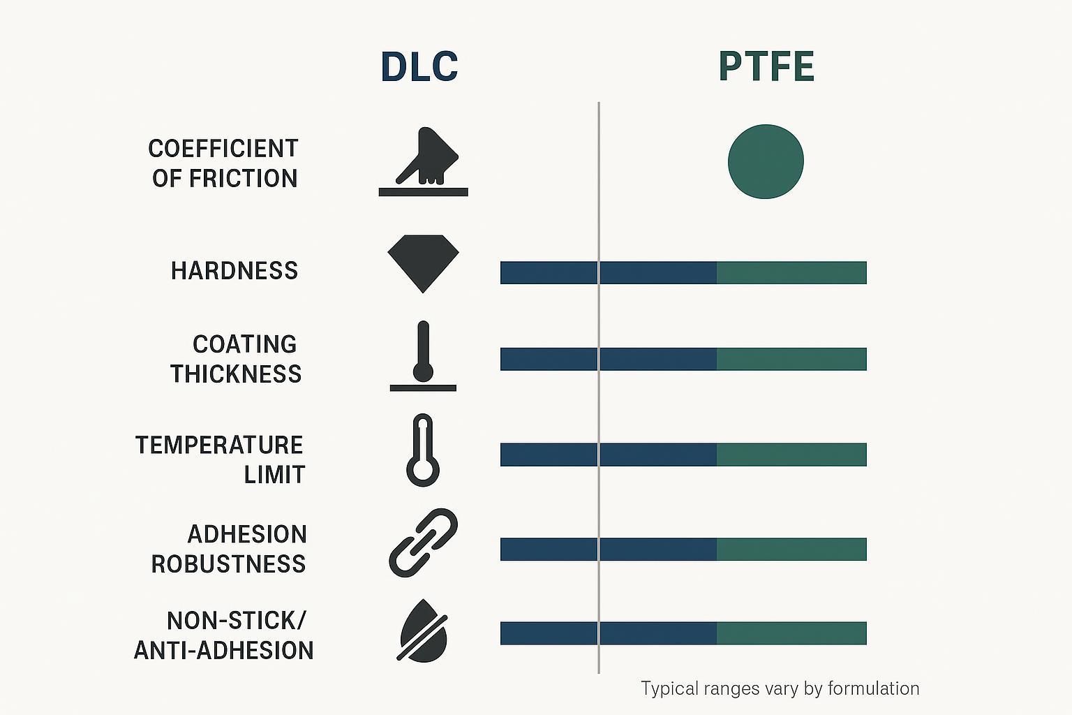
Konformität und Dokumentation
PFAS/PTFE policy watch (US/EU)
If you specify PTFE, treat PFAS policy as a moving constraint—especially for EU-facing supply chains.
- In the US, the FDA maintains an overview of PFAS uses in food-contact contexts and recent market changes; see FDA’s “Authorized Uses of PFAS in Food Contact Applications”.
- In the EU, the broad PFAS restriction conversation is moving through the REACH process. A safe place to monitor status is ECHA’s restriction proposals page within the framework of the EU REACH Regulation (EC) No 1907/2006.
Practical guidance:
- If PTFE is required for performance, document the technical justification and keep your material declarations current.
- Build optionality: qualify a non-PTFE alternative coating system for at least one product family so you’re not forced into a last-minute redesign.
Food contact considerations
If your slitting knives are used in food-contact converting or packaging operations, don’t assume “coating = compliant.” Treat it as a documentation problem:
- Confirm the applicable jurisdiction and product type.
- Keep supplier declarations and any supporting test records aligned to your internal compliance system.
For policy context in Europe beyond REACH, PFAS monitoring requirements also appear in water frameworks such as the EU Drinking Water Directive (Directive (EU) 2020/2184), which signals broader regulatory attention even outside coatings.
Traceability and test records
QA checklist you can copy into your PO / incoming inspection
Use this as a starting template and adjust to your line.
| Artikel | What to specify | Was aufgezeichnet werden soll | Accept / reject cue |
|---|---|---|---|
| Coating type | DLC family / PTFE system + intended use case | Supplier statement + batch ID | Matches PO |
| Architecture (if applicable) | Interlayer + topcoat description | Process route summary | Matches PO |
| Dicke | Target range + tolerance + method | Measured values + locations + sample count | Within tolerance |
| Haftung | Method (e.g., scratch / qualitative check) + criteria | Test record + photos if used | No delamination / unacceptable cracking |
| Oberflächengüte | Ra/Rz method + locations | Values + instrument | Within agreed range |
| Kantengeometrie | Hone / radius requirement + inspection magnification | Microscope photos + notes | No chipping; consistent radius |
| Rückverfolgbarkeit | Batch/heat IDs, shipment/PO linkage | Document pack | Complete and consistent |
| First-run validation | What to monitor (current/force trend, temperature, debris) | First roll log | Stable trend; no early drift |
Tip: The fastest way to avoid “mystery burrs” is to standardize the microscope photo angles and magnification for incoming checks, then compare first-article vs. stable-production references.
For coated slitting blades, the documents that reduce risk are boring—but valuable:
- coating batch identification and process route
- thickness verification (method + sampling plan)
- adhesion test record (method + acceptance)
- hardness/roughness where relevant
- incoming inspection checklist tied to the purchase order
If your supplier can’t consistently provide traceable records, you’ll spend that time later in troubleshooting.
FAQ
F: DLC vs. PTFE für Längsteilmesser: Welche Beschichtung hält länger?
DLC hält beim verschleißbedingten Schneiden in der Regel länger, da es sich um eine harte, dünne Schicht handelt, die Abrieb widersteht und den Zustand der Schneidkante schont. PTFE punktet oft bei der Antihaftwirkung, kann jedoch bei langfristigem Abrieb an Standzeit einbüßen.
F: Warum schneiden PTFE-beschichtete Längsteilmesser anfangs oft gut, bauen dann aber schnell ab?
PTFE kann den Anfangswiderstand und das Anhaften reduzieren, aber die Polymerschicht kann durch abrasiven Staub, Füllstoffe oder Stöße auf die Schneidkante beschädigt werden. Sobald die Oberfläche beschädigt ist, setzen sich Rückstände leichter fest und die Schnittkraft steigt schnell an.
F: Was ist der größte Fehler bei der Spezifikation von DLC-beschichteten Kreismessern?
Die Angabe von „DLC“ ohne Definition des Schichtaufbaus, des Dickenbereichs und der Haftungsakzeptanz. DLC ist eine ganze Beschichtungsfamilie; die Leistung hängt vom Gesamtsystem (Substrat, Zwischenschichten, Deckschicht) und der Schneidkantenvorbereitung ab.
F: Wie beeinflusst die Beschichtungsdicke die Längsteilleistung?
Die Schichtdicke verändert die effektive Geometrie der Schneidkante und kann Ihre Überlappungs- und Spalteinstellungen (overlap/clearance) verschieben. Dünne DLC-Schichten erhalten die Schneidengeometrie meist besser; dickere Polymerschichten können Passungen und das Kontaktverhalten beeinflussen. Überprüfen Sie nach dem Einbau beschichteter Messer immer die Maschineneinstellung.
For bore-fit decisions that establish the locating baseline before coating thickness becomes a variable—ISO 286 H7/h6 vs H7/g6 selection, GD&T coaxiality targets, and assembled TIR verification—see Zentralbohrungstoleranz und Rundlauf: Optimierung von ISO 286-Passungen für Hochgeschwindigkeits-Schneidmesser.
F: Was verursacht Stick-Slip-Effekte (Ruckgleiten) und Rattern beim Schneiden, und können Beschichtungen dies beheben?
Stick-Slip ist meist ein Systemproblem: Die Reibung verändert sich durch Materialrückstände, Transferfilme und elektrostatische Effekte. Beschichtungen können Reibung oder Anhaften reduzieren, aber Sie müssen dennoch Verunreinigungen und statische Aufladung kontrollieren, um Abweichungen im laufenden Betrieb zu verhindern.
F: Stellen PTFE-Beschichtungen ein PFAS-Konformitätsrisiko für EU-Lieferketten dar?
Die PFAS-Gesetzgebung ist im Wandel. PTFE ist Teil der umfassenderen PFAS-Debatte unter der EU-REACH-Verordnung. Es ist daher ratsam, die Materialdeklarationen auf dem neuesten Stand zu halten und den Regulierungsstatus über die ECHA zu überwacht. Für bestimmte Anwendungen reduziert die Qualifizierung einer PTFE-freien Alternative das Compliance-Risiko.
F: Welche QS-Dokumente (QA) sollte ich beim Kauf beschichteter Längsteilmesser anfordern?
Mindestens: Chargenrückverfolgbarkeit der Beschichtung, Schichtdicken-Messverfahren inkl. Ergebnissen, Haftungsprüfprotokoll mit Akzeptanzkriterien sowie ein Wareneingangs-Prüfprotokoll, das die Dokumente der Bestellung (PO) und der Lieferung zuordnet.

Fazit
How to choose (in one minute)
Your decision is usually clear once you name the dominant constraint:
- Wählen Zusatzinhalt when the job is to keep geometry stable and resist wear at speed—especially when your loss-of-quality mode is gradual edge wear.
- Wählen PTFE when the job is to prevent transfer, gumming, and debris anchoring—especially when cleaning events and stick-slip dominate your downtime.
This selection logic reflects the decision framework Maxtor Metal’s engineering team applies when qualifying coating systems for new customer slitting projects.
Step-by-step purchase & commissioning checklist
Use this before you place the PO and again during first-article validation.
Step 1 — Define the job
- Substrate defined (film/foil/paper/nonwoven) and top 2 defect modes documented
- Confirm slitting method (shear/score/crush), speed range, and run length targets
Step 2 — Specify the coating system (not just the label)
- Coating type + intended architecture documented
- Thickness range + tolerance agreed
- Intended operating limits and cleaning constraints documented
Step 3 — Specify edge geometry and inspection method
- Edge geometry/hone specified
- Incoming microscope photo standard defined (magnification, lighting, accept/reject cues)
Step 4 — Define incoming QA & traceability
- Thickness verification method + sampling plan
- Adhesion verification method + acceptance
- Traceability requirements (batch IDs, reports tied to PO/shipment)
Step 5 — Commission on the line (first roll checks)
- Verify overlap and side-load are in the validated window after installing coated knives. On multi-knife setups, also verify that coating thickness is consistent batch-to-batch; even small per-knife variation adds to spacer stack-up error. For the full stack-up math, see Controlling Cumulative Thickness Tolerance in Multi-Knife Slitting.
- Track cutting-force trend (or motor current), knife temperature, and debris/transfer behavior
Step 6 — Validate TCO (life at spec)
- Track time to change + set knives (minutes)
- Track meters-to-defect (or rolls-to-defect) under normal product mix
Key pitfalls to avoid
- treating “DLC” or “PTFE” as a single, fixed specification (architecture and thickness matter)
- ignoring edge prep and honing because “the coating will fix it”
- skipping incoming QA (thickness, adhesion, traceability) and then debugging on the line
Scope & validation note
This guide provides engineering decision support for slitting-knife coating selection. Actual performance depends on web material, adhesive chemistry, knife geometry, overlap, side-load, and machine condition. Always validate settings and acceptance criteria on your own line. Regulatory notes are provided for monitoring and procurement awareness and do not constitute legal advice.
Glossary (quick definitions)
- Überlappen: the axial engagement between top and bottom knives in shear slitting; too much can raise friction and heat. For a full DOE-based analysis of how overlap depth and side clearance interact across substrate types—including the Pareto trade-offs between edge quality and knife life—see Optimierung der Überlappungstiefe und des Seitenabstands von Kreismessern.
- Side-load: the lateral force pressing knives together; affects friction, temperature, and transfer behavior.
- Hone / edge radius: a controlled rounding of the cutting edge; too sharp can chip, too large can increase push/heat.
- Transfer film / transfer layer: material (often adhesive/resin) that deposits on the knife surface and changes friction.
- Stick-slip: friction-driven vibration that can show up as chatter marks or unstable tracking.
Nancy Wu ist ein Senior Manufacturing Engineer (Production Engineering) bei Maxtor Metal, mit 12 years of experience in manufacturing and qualifying industrial blades. Her work focuses on material selection and machinability across common blade materials (including D2, M2, H13, powder-metallurgy steels, and carbide), coating selection for production environments, and high-precision CNC grinding programming.
Zertifizierungen: SME–CMfgE, PMP, Six Sigma Black Belt, Und ASM International-Zertifizierungen.

 English
  Spanish
  Italian
  French
  Portuguese
  Russian
  German
  Arabic
  Hindi
Hindi  Vietnamese
  Indonesian
  Japanese
  Korean