

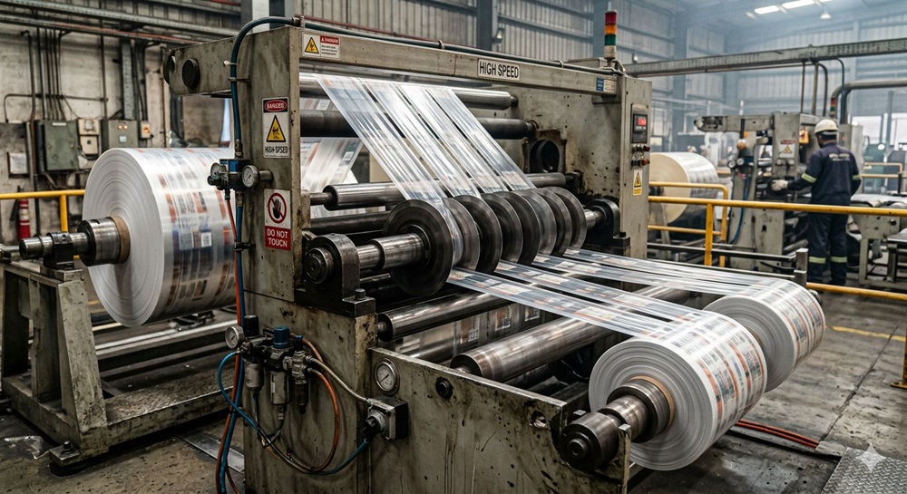
High-speed slitting is unforgiving: small geometry errors show up as burrs, feathering, and unstable lanes long before they show up on a maintenance checklist. At Maxtor Metal, we see runout problems most often when a line is pushed for higher OEE but the slit edge has to stay clean enough for downstream lamination, printing, or welding.
- Why axial runout matters to OEE, scrap, and edge quality
- How axial runout differs from radial runout in practice
- What this guide covers: mechanisms, measurement, mitigation, QA
- Engineering Note: For knife-level specifications including axial runout standards and material grades, see Maxtor Metal’s Precision Circular Slitter Knives.
Die wichtigsten Erkenntnisse: Axial (face) runout changes how knives load the web every revolution. At high speed, “acceptable cold TIR” can still turn into scrap if dynamic wobble and thermal drift aren’t verified.
Define axial runout
Axial runout (often discussed as face runout) is the in-and-out motion of a rotating face relative to the true axis of rotation. If the knife face or clamping shoulder is not perfectly perpendicular to the shaft axis, the knife “wobbles” axially as it spins.
In shop terms, you’re looking for a repeating indicator swing as the arbor/knife stack rotates, usually reported as TIR (total indicator reading) — the peak-to-peak indicator movement in one full turn. (Further down, this guide cites Lion Precision for a metrology-oriented reference on runout measurement.)
Axial vs radial runout
Axial and radial runout create different “signatures” on a slitting line.
- Axial (face) runout is measured on a face and represents face wobble along the shaft axis. It often shows up as uneven knife engagement and one-sided edge defects.
- Radialer Rundlauf is measured on a diameter (OD) and represents off-center rotation perpendicular to the axis. It often shows up as cyclic load variation, vibration, and width/engagement variation.
A concise definition-style contrast is described in Motion Control Tips’ article on radial vs axial runout.
For a deeper metrology-oriented explanation (including non-contact methods), see Lion Precision’s guide to shaft runout measurement.
Common sources in slitting heads
Axial runout rarely comes from one single part. Most of the time it’s a stack-up plus a process issue.
Common sources include:
- Contamination on faces (burrs, adhesive residue, trapped lint, corrosion)
- Damaged shoulders, nicks on spacers, or fretting marks
- Spacer parallelism errors accumulating across the stack
- Knife face flatness and tooling geometry stability changes after regrind or heat exposure
- Uneven clamping torque or distorted clamping rings
- Bearing axial play or preload changes with temperature
Kapoor Enterprises’ overview of axial, radial, and face runout is a helpful cross-check on definitions, static vs dynamic effects, and why “face runout” often reflects both perpendicularity and flatness issues.
Tolerance and assembled TIR
Component tolerances do not automatically equal assembled performance.
- A knife can be within its own flatness/runout spec and still show poor assembled TIR when the spacer stack is uneven.
- A stack can pass at slow rotation cold, then drift out once bearings warm and load changes.
Treat assembled TIR as a system characteristic:
- hardware (knife faces, spacers, arbor shoulder)
- assembly (cleanliness, torque, alignment)
- operation (speed, tension, temperature)
Mechanisms and defects
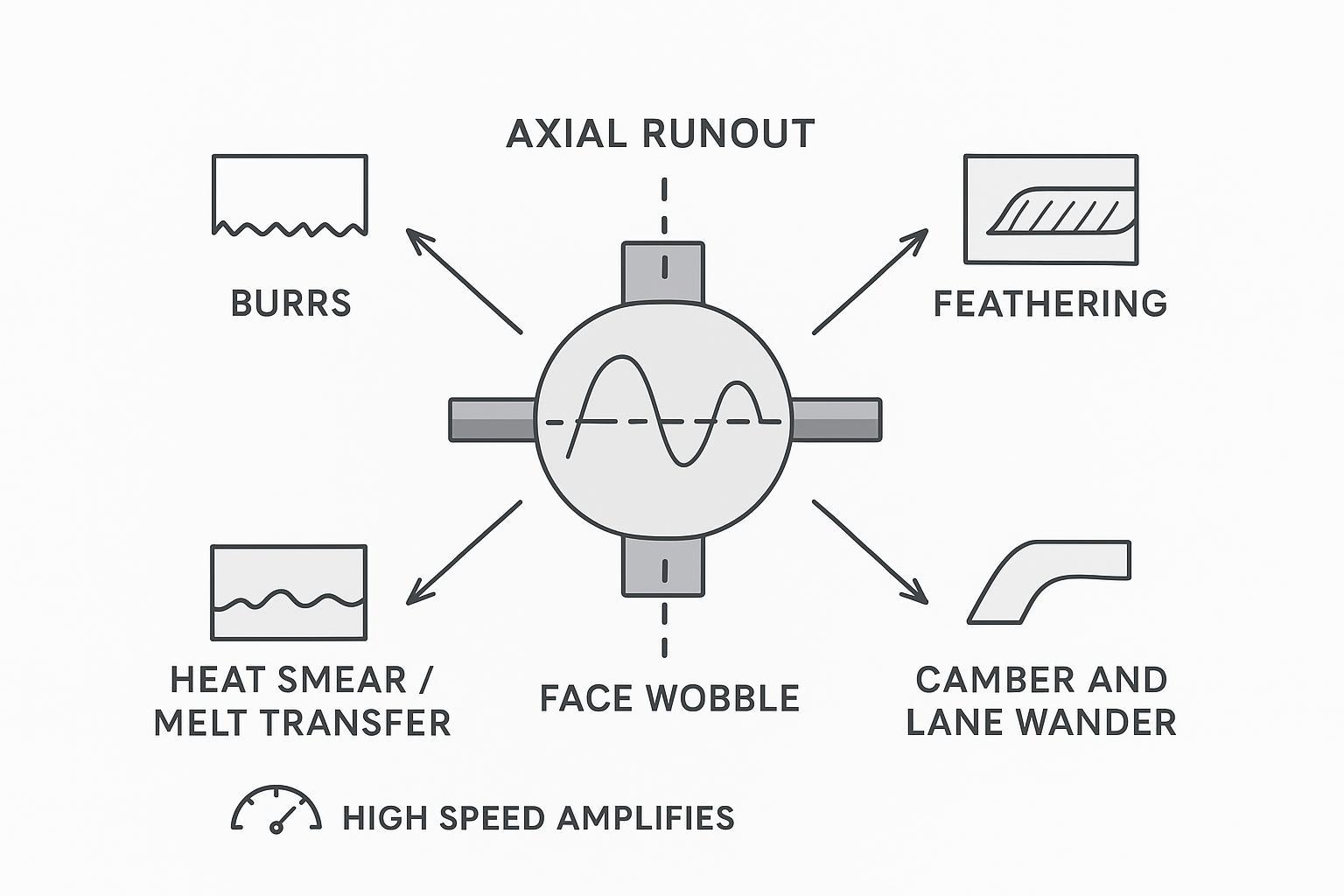
Axial runout changes the contact mechanics every revolution. In shear slitting, that means the overlap/engagement isn’t constant. In crush or score setups, it means the nip load isn’t constant. Either way, “cyclic inconsistency” is a fast path to edge defects.
Burrs and feathering
Burrs and feathering are usually not random — they often have a repeating pattern tied to rotation.
Axial wobble can cause:
- One side of the knife to take more load (one-sided burr)
- The web to see a changing effective overlap (feathering on one edge, clean on the other)
- Intermittent rubbing instead of stable shearing (edge wipe marks)
If operators report “the burr comes and goes” at a steady speed, treat that as a clue that runout, stack parallelism, or vibration is in the loop.
Heat, melt, and transfer
At high line speed, friction spikes become heat spikes. Axial runout can create short, repeating periods of higher contact pressure and rubbing.
That matters because:
- Heat accelerates edge micro-damage and changes cut behavior over the run
- Some webs (films, coatings, adhesives) can soften locally, leading to smear/transfer
- Transfer builds up on faces and makes the runout problem worse (a feedback loop)
When transfer or adhesive build-up on knife faces is the primary failure mode rather than edge wear, the choice of knife surface coating becomes the critical variable. For a diagnostic framework that separates wear-limited from transfer-limited failure—and a field case comparing DLC and PTFE coating performance on a PSA film line—see DLC vs PTFE Coatings for Slitting Blades: Engineer’s Guide.
When runout-driven contact is the root cause of accelerating flank wear and dust generation—rather than transfer build-up—blade surface roughness (Ra) and carbide microstructure become the controlling variables. For a root-cause framework covering Ra thresholds, carbide pull-out mechanisms, and the setup tolerances that prevent secondary dust feedback loops, see Ursachenanalyse zur Schnittstaubbildung: Messerflanken-Ra, Karbid-Mikrostruktur und Einstelltoleranzen.
If the edge defect worsens only after the line stabilizes at speed, consider dynamic runout and temperature-driven movement — not just cold geometry.
Camber and lane wander
While axial runout causes periodic lateral bias, systematic width variations are often driven by spacer stack-up. For a deep dive into spacing alignment, read our companion guide on Managing Cumulative Thickness Tolerance.
When axial runout is one of several concurrent contributors to slit-line wander—alongside tension imbalance, machine alignment, and air entrainment—a systems-level checklist helps sequence the diagnosis efficiently. For that multi-subsystem framework, see Vermeidung von Wellenschnitten beim Folienschneiden: Eine System-Checkliste.
Lane wander is often treated as a tension or guiding problem. But axial runout can bias lateral forces when knife engagement varies around the rotation.
In der Praxis:
- The web sees periodic “side loading” at the cut
- That can show up as camber, wandering lanes, or uneven rewind hardness
If wander correlates with one slitting head or one lane group, measure runout on that arbor and compare to lanes that track clean.
Measurement and verification
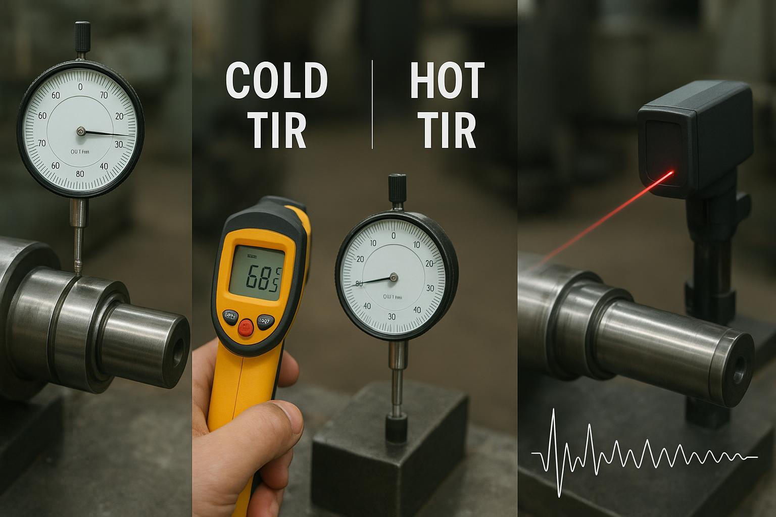
Most runout troubleshooting fails for one of two reasons: the indicator is placed on a feature that hides the real error, or the check is done only cold and slow.
Shop-floor TIR points
Measure where the error can influence cutting. Typical checkpoints (choose what matches your head design):
- Arbor shoulder face (before stacking)
- Spacer faces at multiple points in the stack (to identify where TIR accumulates)
- Knife side face near the cutting edge (axial/face runout symptom)
- Knife OD (radial runout symptom)
A practical approach is to mark the high spot (paint pen) and see whether it follows:
- the arbor (problem stays with shaft/bearing)
- a specific spacer/knife (problem moves with the component)
- the clamp (problem changes with torque)
Dynamic wobble and vibration
Static checks are necessary, but not sufficient for high-speed lines.
Dynamic runout can increase under operating conditions due to thermal changes, load, imbalance, and stiffness limits. Fluke explicitly notes that dynamic runout may only show up under operating conditions, which matches what many converting lines see: “it measures fine, but it cuts poorly at speed.”
When the symptom is speed-sensitive, add at least one of these:
- Non-contact displacement probe at speed (when practical)
- Vibration trend at 1× running speed (to correlate to runout/imbalance)
- Runout check immediately after a speed change or load change
Cold-to-hot drift checks
To counteract thermal-driven axial runout, Maxtor Metal uses controlled stress-relieving cycles and, when specified for the application, kryogene Behandlung during knife manufacturing to improve dimensional stability in high-speed converting environments. (Temperature capability depends on steel grade and heat-treat specification; validate against your operating temperature and OEM requirements.)
If edge quality degrades after warm-up, treat cold-to-hot drift as a required check.
Thermal growth and machine movement are well established in reliability practice; Reliabilityweb’s dynamic movement and thermal-growth white paper is a useful background reference.
A shop-floor-friendly method is:
- Record cold TIR at defined indicator points.
- Run to normal operating speed and steady temperature.
- Re-check as soon as safely possible at “hot” condition (or immediately after shutdown while temperatures are still representative).
This cold-vs-hot comparison approach is consistent with alignment thermal-growth guidance like Ludeca’s thermal growth discussion and Reliabilityweb’s dynamic movement and thermal growth white paper.
Methods and example data for verification
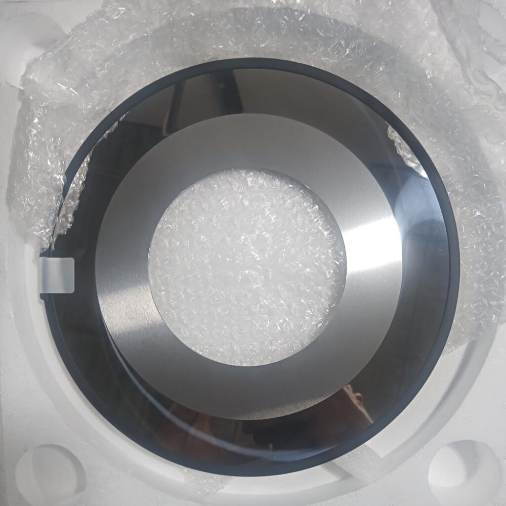
To make runout control repeatable, define measurement points, instruments, and acceptance logic before troubleshooting.
Example measurement setup (shop-floor):
- Instrument: dial indicator (or displacement probe), rigid magnetic base/fixture
- Reference: clean, deburred contact surface; consistent preload
- Rotation: 360° slow roll for static TIR; mark the high spot for tracking
- Record: max–min as TIR, plus temperature/state (cold vs hot)
Example dataset (illustrative):
- Point A (arbor shoulder face): cold TIR 0.008 mm → hot TIR 0.014 mm
- Point B (mid-stack spacer face): cold TIR 0.012 mm → hot TIR 0.020 mm
- Point C (knife side face near edge): cold TIR 0.015 mm → hot TIR 0.028 mm
What the example suggests: the error grows with temperature and accumulates in the stack, so cleaning/parallelism/torque control and hot-condition verification become the priority.
Repeatability note (quick R&R check): have two operators measure the same point three times. If the spread is large compared to your acceptance band, improve fixturing, indicator contact angle, and the worksheet definition before blaming the hardware.
Mitigation strategies
Fixing axial runout is about reducing stack-up sensitivity and controlling what changes between “inspection” and “production.”
Precision hardware and QA
Start with the parts that define the geometry.
- Confirm knife faces and spacer faces are clean, flat, and free from raised dents.
- Control spacer parallelism as a system, not as individual “good parts.”
- Standardize clamp torque and tightening sequence.
If you are evaluating circular knives for high-speed slitting, the product-page specs (materials, tolerances, surface finish options) matter because they affect assembled behavior. See Maxtor Metal circular knives & blades for the supported configurations and published precision ranges.
Brief QA + service note (≤30 words):
- Heat/lot traceability, hardness and runout inspection records
- Shipping documentation and customs coordination support available for international orders.
Bearings, balance, and stiffness
If a head “measures okay” but becomes unstable at speed, look beyond the knives.
- Bearings: axial play, preload condition, lubrication state, and mounting fits
- Balance: rotating mass balance on the assembled stack and any adapters
- Stiffness: arbor diameter, overhang, support spacing, and frame stiffness
The practical goal is to avoid a system where small face wobble excites vibration that then increases the effective runout during cutting. For the upstream locating decisions that directly drive this wobble—bore fit selection (ISO 286 H7/h6 vs H7/g6), GD&T coaxiality targets, and a repeatable assembly verification routine—see Zentralbohrungstoleranz und Rundlauf: Optimierung von ISO 286-Passungen für Hochgeschwindigkeits-Schneidmesser.
Setup control and SOPs
Runout control is repeatability control.
Minimum SOP elements that prevent “mystery drift”:
- Clean-and-check protocol for all faces before stacking
- Defined indicator points and a standard worksheet for each head
- Clamp torque value + tightening sequence
- Warm-up procedure and a defined “verify hot” point for high-speed jobs
For thin-film and nonwoven lines where dynamic contact consistency is the primary challenge, a spring-loaded zero-clearance setup provides continuous preload compensation; see Spring-Loaded Setup for Zero-Clearance Shear Slitting.
Acceptance and traceability

If you don’t define acceptance, you’ll argue about causes every time scrap rises.
Material/gauge acceptance bands
Define acceptance bands per material family and gauge range.
Below is a starting-point example (not a universal spec). You should validate against your material, knife type (shear/crush/score), and downstream edge requirements.
Example acceptance bands (assembled face TIR at knife near edge):
- Thin films & coated webs (high sensitivity): ≤ 0.015 mm cold, ≤ 0.020 mm hot
- General packaging laminates / paper (medium sensitivity): ≤ 0.020 mm cold, ≤ 0.030 mm hot
- Thick / filled / abrasive webs (edge-wear dominated): ≤ 0.025 mm cold, ≤ 0.035 mm hot
Decision rule (practical):
- Wenn hot TIR exceeds the band or the edge defect is periodic at steady speed: stop and isolate the high spot (arbor vs spacer vs knife), then re-check after corrective action.
- Wenn cold is OK but hot drifts high: review bearing/preload condition, warm-up SOP, clamp torque/sequence, and stack parallelism.
Note: The numbers above are intentionally conservative examples for high-speed lines. Use them as a template for building your own bands from run logs and edge-quality outcomes.
- Thin films and coated webs are usually more sensitive to wobble and heat.
- Abrasive or filled materials often amplify edge wear, which can hide a runout root cause.
The key is to agree on “acceptable edge” and “acceptable TIR” for each product family, then hold the system to it.
Run logs and TIR templates
A simple run log turns runout from a one-time diagnosis into a controlled variable.
Include:
- Date/time, head ID, operator
- Material, gauge, line speed, tension setpoints
- Cold TIR readings (points defined)
- Hot TIR readings (same points)
- Edge quality notes (which side, which lanes)
- Corrective action taken and outcome
Standards and references
For formal definitions and tolerancing language, the most commonly cited standards families are:
- ASME Y14.5 (runout symbols and GD&T intent)
- ISO 1101 (GPS tolerancing, including runout)
- ISO 230-7 (geometric accuracy of axes of rotation)
On the practical measurement side, references like Lion Precision’s shaft runout measurement guide and Kapoor Enterprises’ runout overview help translate the standard language into shop checks.
Fazit
If you want clean edges at production speed, treat axial (face) runout as a dynamic, assembled-system variable—not a single cold measurement on one part. In practice, the strongest predictors of edge stability are (1) where you measure (near-edge face points that influence engagement), (2) whether you verify hot-condition TIR after warm-up, and (3) whether your spacer/knife stack is built with repeatable parallelism and cleanliness.
A practical way to turn this into day-to-day control is to link edge defects to runout signatures. Periodic, rotation-linked burr or feathering at steady speed usually means the system is seeing cyclic engagement changes—so track the high spot, isolate whether it follows the arbor, a spacer, or the clamp, and then confirm the fix with a short hot-condition re-check. This avoids the common trap of “it measured fine” while the line still makes scrap.
Finally, remember that acceptance bands and procedures only work when they’re documented and repeatable. A simple worksheet that captures cold vs hot TIR, torque sequence, and first-article edge notes lets you build your own material-specific limits from real outcomes. Over a few runs, you’ll be able to predict which jobs need tighter stack discipline, warm verification, or balance checks—before edge quality starts drifting.
Jesse Xu ist ein Senior Quality Engineer (QA) bei Maxtor Metal mit 15 years of experience in industrial blades and process quality. His background includes Fehleranalyse—distinguishing chipping and abnormal wear driven by heat-treatment process variation versus material segregation. Certifications: ASQ-CQE, ISO 9001 Lead Auditor, ASNT Level II.
Document control and safety note
- Zuletzt geprüft: 2026-05-21
- Safety: Always follow your OEM manual and site safety procedures. Any at-speed runout or vibration measurement should be performed only by qualified personnel with appropriate guarding, lockout/tagout practices, and risk assessment.
- Hinweis: This article is an educational guide. Any Maxtor Metal product references are provided for context on available blade configurations.
- Key takeaways on axial runout, edge quality, and TCO
- Immediate next steps: measure, log, stabilize, verify warm
- Ongoing improvement: balance, QA audits, and reviews
The core conclusion is simple: axial runout is not just a metrology number — it’s a repeatable load error that directly shapes edge quality at speed. When you control face cleanliness, stack-up parallelism, and hot-condition verification, you reduce scrap, extend knife life, and protect OEE.
Immediate next steps you can run this week:
- Measure axial (face) TIR at defined points, not “where it’s easy to reach.”
- Start a run log with cold and hot readings.
- Stabilize setup: clean faces, standardize torque, isolate the component that carries the high spot.
- Verify warm on the jobs that run fast or run hot.
Over time, treat it like a system capability project:
- Balance rotating assemblies when speed increases.
- Audit QA records and measurement repeatability.
- Review trends by head ID and material family.
Knife-level precision specifications, heat-treat traceability records, and runout inspection data for circular slitter knives used in high-speed converting applications. Specification sheets are available on the Maxtor Metal product page.
Case study: packaging film slitting (BOPP/PE) — before vs after
The following data comes from Maxtor Metal’s field support for a packaging film converter running BOPP/PE; the customer name has been anonymized.
Anwendung
- Industry: packaging film slitting (BOPP / PE)
- Primary material: BOPP packaging film (with some PE)
- Thickness range: 25–80 μm
- Line speed: 350–600 m/min
Knife stack example
- Circular knives per set: 16–20
- Spacers/sleeves per set: 32–40
- Shims: used for final width fine-tuning
One-sentence problem statement
At high speed, the line showed burr and feathering, and slit-width repeatability was unstable after changeovers.
What we changed
- Measured and labeled spacers one-by-one; sorted in 0.001 mm bins and paired for assembly.
- Standardized clamp torque value, tool, and sequence; recorded pre- and post-torque TIR.
- Implemented a face-contact cleaning and deburring routine (spacers, knife faces, clamping shoulders).
- Added first-article width + edge inspection and a run log.
Before vs after (conservative example)
| Metrisch | Vor | After |
|---|---|---|
| Slit width variation | ±0.070 mm | ±0.025 mm |
| Burr / edge defect rate | 5–7% | 1–2% |
| Umrüstzeit | 50–55 min | 33–36 min |
| Pre/Post-torque TIR | 0.012–0.016 mm | 0.005–0.008 mm |
| Spacer thickness spread | 0.006 mm | 0.002 mm |
Key takeaways from the case
- Cold, slow-roll TIR can look acceptable, yet hot-condition axial runout grows and edge quality begins to fluctuate.
- The most actionable checkpoint was not any single knife. It was assembled hot-condition TIR plus face cleanliness across the spacer/knife stack.
- On packaging films, small edge damage tends to amplify into burr, feathering, and uneven rewind edges downstream.
FAQs:
Frage: Was ist der Axialschlag (axial runout) an einer Messerwelle?
Ответ: Der Axialschlag ist das Hin- und Her-Wackeln einer rotierenden Fläche (Planschlag) relativ zur Achse der Welle. Beim Längsschneiden verändert dies bei jeder Umdrehung den Eingriff des Messers und kann zu einseitigen Schnittkantenfehlern führen.
Frage: Axialschlag vs. Radialschlag: Was verursacht Grate?
Ответ: Beides kann dazu beitragen, aber Axialschlag (Planschlag) erzeugt oft einen ungleichmäßigen Eingriff, der sich als einseitiger Grat oder Ausfransung zeigt. Radialschlag äußert sich häufiger durch zyklische Vibrationen und ungleichmäßige Belastung.
Frage: Wie misst man den Axialschlag (Planschlag) mit einer Messuhr?
Ответ: Setzen Sie die Messuhrspitze auf die gewünschte Fläche (Wellenbund, Distanzring-Vorderseite, Messerseitenfläche), bringen Sie eine leichte Vorspannung auf, drehen Sie um 360° und notieren Sie den Wert max minus min. Dieser Spitzen-zu-Spitzen-Wert ist der TIR (Total Indicator Reading).
Frage: Was ist ein akzeptabler TIR für Hochgeschwindigkeits-Längsschneiden?
Ответ: Es gibt keine universelle Zahl. Legen Sie Akzeptanzbänder je nach Material und Dicke fest und prüfen Sie unter realen Bedingungen (einschließlich Warmprüfungen). Ein „akzeptabler kalter TIR“ kann im Betrieb versagen, wenn der dynamische Schlag zunimmt.
Frage: Warum ist die Schnittkantenqualität bei niedriger Geschwindigkeit gut, bei Produktionsgeschwindigkeit jedoch mangelhaft?
Ответ: Höhere Geschwindigkeiten verstärken dynamische Effekte: Vibrationen, Unwucht, Lastwechsel und thermische Ausdehnung. Diese können den effektiven Rundlauffehler vergrößern und die Messerbelastung verändern, selbst wenn statische Messungen akzeptabel aussahen.
Frage: Wie prüfe ich die Rundlaufabweichung (Drift) von kalt nach warm an einem Schneidkopf?
Ответ: Zeichnen Sie den kalten TIR an festen Messpunkten auf, fahren Sie bis zur stabilen Produktionstemperatur und prüfen Sie dann erneut im warmen Zustand (oder sofort nach dem Herunterfahren, solange die Temperaturen noch repräsentativ sind). Vergleichen Sie beide Datensätze, um die Drift zu quantifizieren.
Frage: Was verursacht neben Spannung und Bahnlaufregelung ein Verlaufen der Bahnen (lane wander)?
Ответ: Axialschlag kann eine periodische Seitenbelastung am Schnitt erzeugen, die Bahnen seitlich auslenken kann. Wenn das Verlaufen bei einem bestimmten Kopf oder einer Bahngruppe auftritt, vermessen Sie diese Welle/diesen Stapel, bevor Sie die Bahnlaufregelung ändern.
Frage: Wie kann ich den Axialschlag reduzieren, ohne den gesamten Schneidkopf auszutauschen?
Ответ: Beginnen Sie mit der Reinigung und dem Zustand der Auflageflächen, isolieren Sie dann die Komponente mit dem höchsten Punkt (High Spot), standardisieren Sie das Anzugsdrehmoment und die Reihenfolge, und prüfen Sie im warmen Zustand. Wenn das Problem weiterhin besteht, prüfen Sie Lager/Vorspannung, Auswuchtung und Steifigkeit.

 English
  Spanish
  Italian
  French
  Portuguese
  Russian
  German
  Arabic
  Hindi
Hindi  Vietnamese
  Indonesian
  Japanese
  Korean