

How to use this guide (scope & assumptions): The ranges and troubleshooting steps below are practical starting points for Kreisschlitzmesser in typical converting lines. Actual optimum settings depend on your machine design (holder stiffness, runout, spacer stack), web support, and substrate variability—always validate with a controlled trial and change one variable at a time.
Technischer Hinweis: For knife-level specifications, including axial runout standards and material grades, see Maxtor Metal’s Precision Circular Slitter Knives.
If you’re trying to cut cleaner edges with fewer changeovers, the fastest win is usually not a new machine—it’s matching edge geometry to how your material behaves under tension. Maxtor Metal sees the same pattern across film, nonwoven, textile, and laminate lines: a bevel that works beautifully on a soft web can chip, rub, or raise burrs the moment rigidity goes up.
- Why edge geometry matters for uptime, burr control, and TCO
Edge geometry sets how the knife enters the web, how forces distribute, and whether the cut stays stable as the edge wears. It also controls your most common defect costs—this is the heart of slitting burr control blade geometry. A mismatch shows up as repeating waste: unplanned blade changes, width drift, edge fuzz/dust, downstream jams, and scrap.
- How material rigidity and setup drive Single bevel, double, or compound choices
Rigidity changes the “support” the edge needs. Soft webs benefit from low-force entry and good support against flutter. Stiff webs punish fragile edges and amplify side thrust, runout, and over-aggressive overlap.
- What this guide delivers: a selection framework with starting parameters
You’ll get a rigidity-led way to choose single bevel, double bevel, oder compound/micro-bevel geometry, plus setup windows and checks that keep cut quality stable as conditions change. Throughout, treat it as a single bevel vs double bevel vs compound bevel slitter blade selection problem—not a one-size-fits-all grind angle.
Edge mechanics (bevel geometry for circular slitter knives)
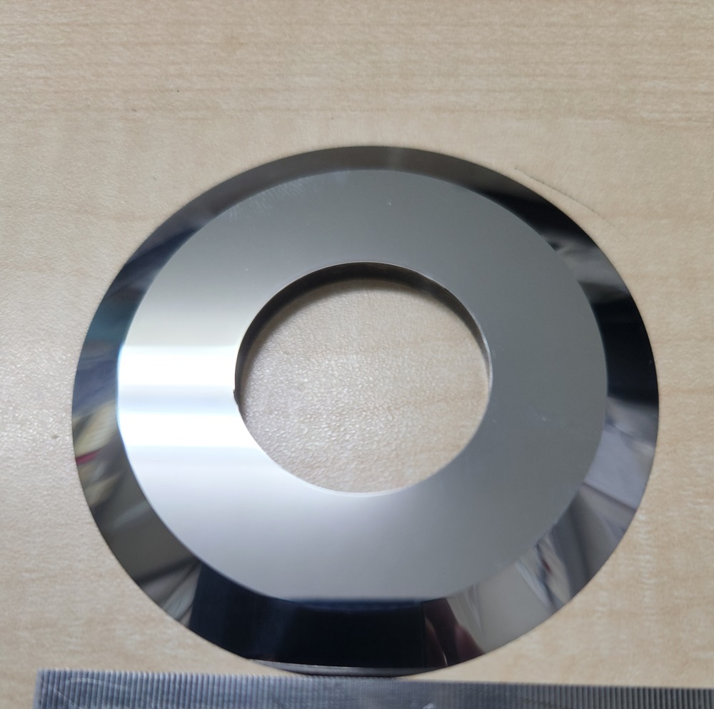
Single bevel mechanics
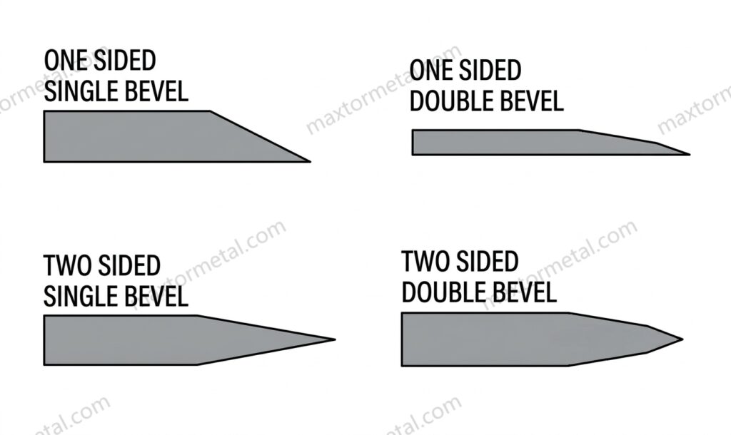
A single bevel is directional by nature. One side of the edge is doing most of the “work,” which can make initial entry feel sharp and efficient—especially on softer webs.
The tradeoff is side force. Single bevels can “steer” the cut if web guiding, knife alignment, or side load isn’t controlled. That’s why single bevels are often described as handed: mount orientation matters, and reversing direction can change edge quality.
Asymmetric edges can behave directionally: an uneven wedge angle changes how cutting forces resolve into the web, which can influence tracking if alignment and side load aren’t controlled.
Double bevel balance
A double bevel splits the wedge more evenly. In practice, that often means:
- More neutral tracking (less tendency to push to one side)
- Better tolerance to small alignment errors
- More consistent edge quality across direction changes
Double bevel is usually the safest “baseline” choice when you need stable quality across multiple materials, widths, or shift-to-shift setup variation.
Compound/micro-bevel support
Compound edges (often a primary bevel plus a small secondary bevel at the tip) are a way to keep sharp entry while giving the edge more support.
Think of it as “sharp where it matters, reinforced where it fails.” When rigidity or abrasiveness is high, a micro-bevel can reduce chipping and premature rounding without turning the knife into a blunt wedge.
Rigidity-driven selection
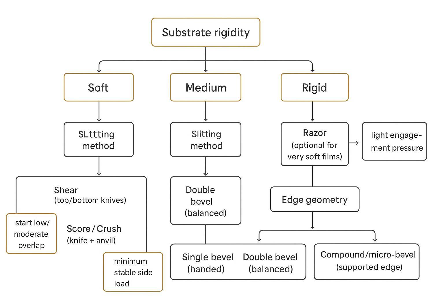
Mapping rigidity to geometry (choose bevel by material rigidity)
You don’t need a lab to bucket rigidity. For most converting lines, a practical classification uses:
- Caliper / thickness (quick screen)
- Handling behavior (bend/cantilever feel)
- Machine behavior (flutter, wandering edge, sensitivity to tension)
For paper and board, stiffness is often specified using standardized bending-resistance methods (for example, ISO’s paper/board stiffness standards such as ISO 2493-2:2020 (Taber-type tester) and the broader principles in ISO 5628:2019), which helps when you need to compare grades objectively.
A useful shop-floor mapping looks like this:
- Soft: thin films/foils, low basis-weight nonwovens, stretchy webs (flutter-prone)
- Medium: most packaging films, coated papers, medium nonwovens
- Rigid: boards, stiff laminates, high-caliper composites (edge damage/dust becomes dominant)
When to prefer Single bevel
Single bevel is most effective when you need a clean, low-force entry and you can control direction and support.
Prefer single bevel when:
- The web is soft and sensitive to crushing or edge deformation
- You want strong initial “bite” at lower cutting load
- The line runs one dominant direction and you can keep knife orientation consistent
Red flags for single bevel:
- Edge quality changes when you reverse direction
- You’re compensating with extra side load or extra overlap
- You see increasing burr/fuzz as the edge wears (fragile tip or wrong orientation)
Bidirectional vs. handed use
If your process reverses direction (or you swap top/bottom knife orientation frequently), this is where single bevel often causes confusion.
- Single bevel: treat as handed. Mark knife orientation in the tooling log and on the arbor/spacer map.
- Double bevel: typically more bidirectional and forgiving.
- Compound: depends on whether the base is single or double; a compound single bevel still behaves as handed.
Profi-Tipp: If operators can’t reliably keep bevel orientation consistent across changeovers, a double bevel or compound-double bevel often reduces “mystery defects” more than any micro-adjustment.
Setup parameters
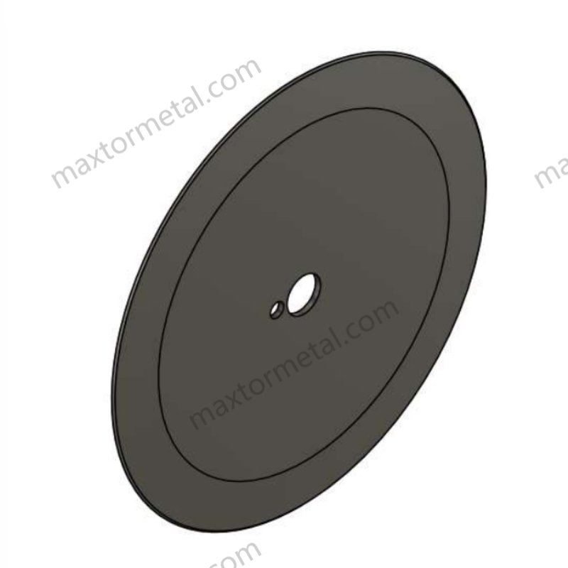
Shear slitting windows
For a deeper walkthrough on dialing in engagement variables, see optimizing overlap depth & side clearance.
Practical starting windows (overlap & side load)
Use these starter ranges as a first pass, then tune based on edge quality and heat/friction signs:
- Soft webs (e.g., PE film): overlap 0.30–0.50 mm; light side load. On soft or compliant webs where maintaining zero-clearance contact under tension variation is a challenge, a spring-loaded holder system can stabilize the cut point; see Spring-Loaded Setup for Zero-Clearance Shear Slitting.
- Medium rigidity webs (e.g., BOPP/CPP): overlap 0.45–0.70 mm; medium side load
- Rigid / laminate webs (e.g., PET / laminates): overlap 0.60–0.90 mm; medium–high side load
Adjustment order (minimize needless wear):
- Reduce overlap if you see dust/fines, heat marks, or melted buildup
- Verify alignment/runout and spacer cleanliness
- Increase overlap or side load only to the minimum that stabilizes the cut
Note: “Side load” here is intentionally expressed as relative levels because different holders use different scales and units.
Shear slitting succeeds when you get true scissor action: alignment, controlled overlap/penetration, minimum stable side load, and consistent spacer stack.
Start with this order (change one variable at a time):
- Verify knife condition (edge, nicks) and runout
- For bore fit selection (H7/h6 vs H7/g6) and the assembly routine that keeps TIR repeatable across changeovers, see Central Bore Tolerance and Runout: ISO 286 Fits for Slitter Knives.
- Verify holders/spacers are clean and parallel (see cumulative thickness tolerance for multi-knife stacks)
- Set overlap/penetration conservatively
- Add only the side load needed to stay stable
- Tune tension and speed relationship
For deeper setup logic and troubleshooting, keep your setup notes aligned with standardized measurement practices for web properties and machine geometry (e.g., stiffness and thickness test standards, and consistent runout/inspection routines).
Symptoms → likely first adjustments:
- Burr or heavy edge roughness: reduce aggressive overlap first; then check clearance/alignment and edge sharpness.
- Dust/fines: overlap or side load is often too high for the rigidity of the web; confirm knives aren’t rubbing.
- Incomplete cut / intermittent tag: overlap too low, side load too low, or knives dull.
If you want a step-by-step sequence built around practical checks, Maxtor Metal’s shear slitting setup guide is a good companion reference.
Crush/score specifics
Crush/score slitting is pressure-driven: a knife engages an anvil and separates by controlled deformation. It’s simpler mechanically, but it is unforgiving when pressure is used as a substitute for sharpness.
Starting points that hold up across many lines:
- Keep the knife as sharp as the process allows; don’t “force” a dull edge with pressure.
- Verwenden minimum pressure/penetration that produces a stable cut.
- If dust rises as you increase pressure, you’re usually past the sweet spot.
In crush/score slitting, keep angle selection and pressure settings tied to your substrate’s deformation behavior and measured thickness. For thickness measurement, use an appropriate standard for the material family (e.g., ISO 4593 for plastic film/sheet thickness by mechanical scanning, or ISO 5084 for textile and nonwoven thickness under specified pressure).
Edge finish and coatings
Edge finish matters because it changes friction and how quickly the web heats or drags at the cut point.
Use a simple selection mindset:
- If you see melt edge or heat marks on films, look at friction sources first (pressure, overlap, edge condition, cleanliness) before changing geometry.
- If you see abrasive wear (edge rounding, polish band growth) on filled materials, a supported edge (compound/micro-bevel) often holds quality longer.
If you’re specifying new tooling, keep the request measurable:
- Edge geometry (single/double/compound)
- Target application and substrate family
- Quality metrics you care about (burr, fuzz, dust, width tolerance)
- Surface coatings (DLC or PTFE) add another layer to this selection: a coating that works on one substrate type can degrade quickly on another depending on whether your line is wear-limited or transfer-limited. For a selection framework with field case data, see DLC vs PTFE Coatings for Slitting Blades: Engineer’s Guide.
For readers evaluating sourcing and spec options, Maxtor Metal’s circular knives and blades page is the right starting point for circular knife formats and customization scope.
Material playbooks
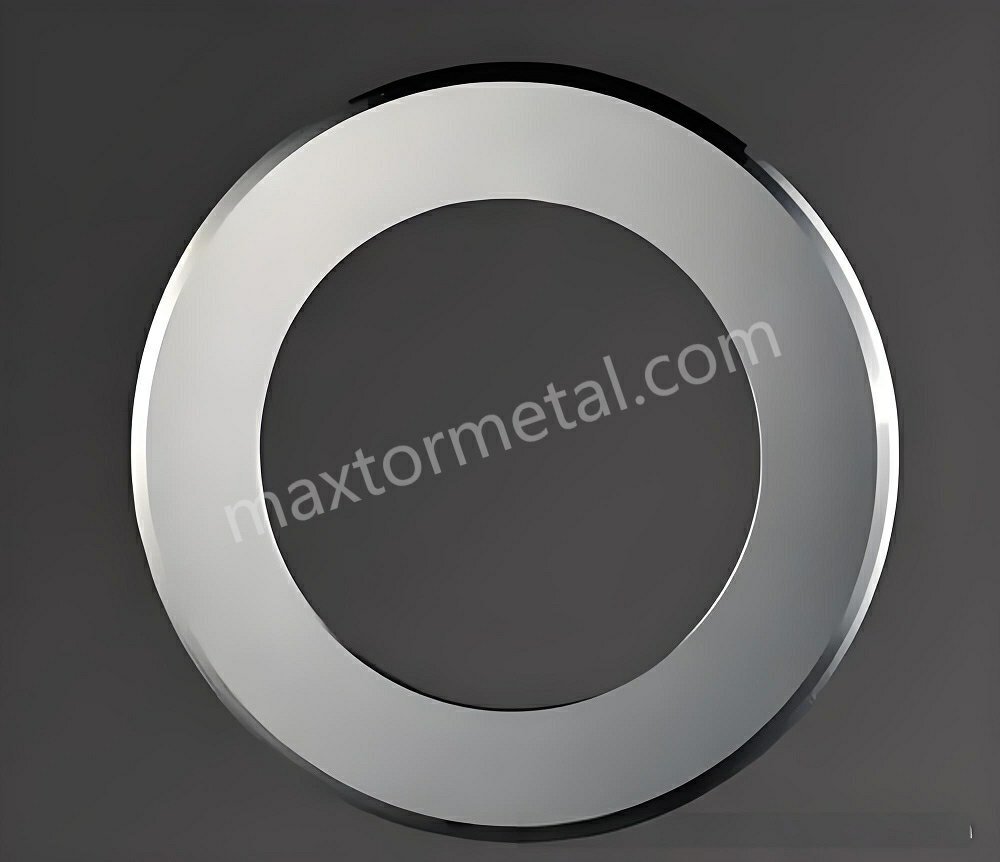
Films and foils
What tends to matter most is flutter control, sharp entry, and avoiding heat/friction.
Starting guidance:
- Soft, thin films: single bevel or compound with sharp entry; keep engagement light and web support stable.
- Foils or foil-laminates: edge support becomes more important; double bevel or compound often reduces burr growth over time.
Common defects by rigidity bucket (what to check first):
- Soft webs: edge stretching; melted dust buildup (often too much overlap/pressure or friction/rubbing)
- Medium rigidity webs: burr; dust
- Rigid webs: burr; incomplete cut / edge cracking
Checks that prevent wasted trials:
- Confirm tension stability before blaming the knife.
- Track edge condition by time and by footage; soft webs can mask wear until defects spike.
Paper/board and laminates
Paper and board often reward stable shear action and consistent clearance. Laminates can be “rigid overall” but still have brittle layers that chip edges or create dust.
Starting guidance:
- Medium paper / coated paper: double bevel is a common stable baseline.
- Rigid laminates / board-like structures: compound or robust double bevel; reduce over-aggressive overlap to control dust.
Key quality checks:
- Edge dust vs burr: dust often points to over-aggressive settings, not just edge geometry.
- If slit edges “feather,” verify edge sharpness and holder alignment before increasing pressure.
Textiles/nonwovens & elastomers
Mini case study: hygiene-grade PP spunbond (25 gsm) at 380–520 m/min
Data note: The figures below come from Maxtor Metal’s project support for a hygiene nonwoven manufacturer; the customer name has been anonymized.
A hygiene nonwoven converter running PP spunbond ~25 gsm (about 0.18–0.22 mm, no filler) used the slit web in a backsheet lamination process where edge cleanliness affected rewinding stability and downstream ultrasonic bonding.
Line basics (shear / wrap configuration): 3,200 mm web width, ~20 lanes (90–160 mm lane widths), pneumatically loaded top-knife holders. The line **ran 380–520 m/min**; the team also used **~3–4% bottom-knife overspeed** to stabilize the cut point.
Industry note: A commonly cited principle in shear slitting is that a small bottom-knife overspeed (3–5%) stabilizes the cut point and prevents web buckling at the cut point.
Before/after snapshot (key metrics):
| Metrisch | Vor | After |
|---|---|---|
| Primary defects | Fuzz / fiber stringing / edge pull / lint accumulation | Reduced fuzz and stringing; lower edge pull; less lint buildup |
| Severity (internal scoring) | Fuzz 8/10, stringing 6/10 | Fuzz 4/10, stringing occasional |
| Operator intervention | Cleaning every 2–3 parent rolls; 6–8 interventions/shift; visible lint after ~90 min | 1–2 interventions/shift; cleaning downtime reduced by roughly one maintenance cycle per shift |
| Knife life | ~35–42 h; edge deterioration visible after ~2 shifts | ~55–68 h (about +45–60%) |
| Scrap / rework | Ausgangslage | Edge-trim waste down ~18–25%; rewind rejection complaints reduced noticeably |
What changed (the actions that mattered):
- Geometry: standard double bevel → compound bevel top knife (primary ~45° with a small ~15° relief/micro-bevel)
- Overlap: moved to a stable window of 0.35–0.50 mm (rule: don’t increase overlap first when fuzz appears—verify tension drift and lint buildup first)
- Side load: medium–high → light–medium, targeting the minimum pressure needed to maintain a closed nip
- Process controls: unwind tension variation held to ±5%, slower acceleration ramp, improved spreader-roll alignment, and a tuned taper rewind profile
- Operator rules: slit-zone lint cleaning every 4 Stunden, knife inspection every shift change, and no continued production after first visible micro-chip
Two common “quick fixes” made things worse:
- Increasing side load to high reduced stringing briefly, but increased heating, lint, and wear.
- Increasing overlap from ~0.45 mm to ~0.90 mm eliminated intermittent tags but began to compress and bead the edge and accelerated wear.
Key takeaway: compound bevel geometry widened the stable operating window, but it could not compensate for unstable tension (e.g., >±7% drift) or poor holder alignment above ~520 m/min.
These materials often fail by fuzz, stringing, and edge pull—symptoms that can look like a dull edge even when the knife is sharp.
Starting guidance:
- Nonwovens (soft): sharp entry helps; single bevel can work well if direction is controlled.
- Textiles (tough, fibrous): double bevel or compound often holds edge quality longer.
- Elastomers: focus on minimizing drag and controlling tension; a supported edge reduces “grab.”
⚠️ Warnung: When you’re chasing fuzz/stringing, avoid the instinct to keep increasing side load or pressure. It can hide the root cause (web support, alignment, edge geometry) while accelerating wear.
Decision and TCO
Step-by-step decision tree
Use this as a repeatable changeover meeting checklist:
- Classify rigidity: soft / medium / rigid (by caliper + handling + machine behavior)
- Confirm slitting method: shear vs score/crush
- Choose geometry:
- Soft + directional stability available → single bevel (or compound for longer life)
- Mixed materials / frequent reversals → double bevel
- Rigid/abrasive / edge chipping risk → compound/micro-bevel support
- Set conservative engagement first; tune overlap/pressure upward only as needed
- Lock in a verification routine (below)
Quality metrics and checks
Define “good” in measurable terms before you trial geometry changes:
- Edge quality: burr height, fuzz length, dust level (visual standard photo)
- Width stability: slit width tolerance and drift over a run
- Heat/friction signs: melt edge, polish bands, debris accumulation
- Uptime metrics: changeover time, rework/scrap rate, blade life in footage/time
A simple verification cadence:
- Check first article: 5–10 minutes into run
- Check mid-run: after stabilization
- Check end-of-run: confirm wear trend
Maintenance and resharpening
Edge geometry and maintenance are connected. If you resharpen, you need repeatability.
Controls that protect TCO:
- Record bevel type, orientation (if single), and the last sharpening parameters
- Inspect for runout and nicks before reinstalling
- Don’t compensate for dull edges with pressure; it raises defect costs faster than it saves time
Fazit
- Key takeaways: match rigidity, geometry, and setup for stable quality
Rigid webs punish fragile edges and amplify setup errors; soft webs punish poor support and tension control. The most reliable path is to treat bevel selection and setup as one system: choose the edge that fits rigidity, then tune overlap/pressure and side load to the minimum that produces a stable slit.
In practice, that’s also the best way to lower TCO: fewer unplanned changeovers, less scrap, and less time spent chasing defects. If you’re standardizing these choices across lines, Maxtor Metal can help you translate your substrate mix and defect profile into a consistent bevel + setup starting point.
- Next steps: validate with trials, document settings, monitor defects
Run one controlled trial per material family, document the geometry and setup window that works, and keep a defect photo standard so operators can react the same way every time.
If you want a fast starting recommendation, share: substrate type + caliper, slitting method, line speed, and 2–3 photos of the current defect. We’ll map it to a rigidity bucket and propose a baseline bevel and setup window.
FAQ
Frage: Was ist der Unterschied zwischen einem Messer mit einseitigem und beidseitigem Anschliff?
Antwort: Ein Messer mit einseitigem Anschliff hat eine asymmetrische Schneide, die dazu neigt, in eine bevorzugte Richtung zu schneiden, während ein beidseitiger Anschliff symmetrisch und neutraler ist. Ein einseitiger Anschliff kann einen scharfen Anschnitt bei weichen Bahnen bieten, aber ein beidseitiger Anschliff ist meist fehlertoleranter, wenn die Einstellungen variieren oder die Richtung umgekehrt wird.
Frage: Wann sollte ich eine zusammengesetzte Schneide (Mikro-Fase) bei Kreismessern verwenden?
Antwort: Verwenden Sie eine zusammengesetzte Schneide/Mikro-Fase, wenn die Schneide mehr Stabilität benötigt – typischerweise bei höherer Steifigkeit, abrasiven Füllstoffen oder wenn scharfe, einseitige Anschliffe zu schnell ausbrechen oder stumpf werden. Es ist ein praktischer Kompromiss zwischen Schärfe und Standzeit.
Frage: Warum hat sich die Gratbildung durch die Änderung der Anschliffgeometrie verschlechtert?
Antwort: Grate nehmen in der Regel zu, wenn die Einstellung für die neue Geometrie zu aggressiv gewählt ist – häufige Ursachen sind übermäßige Überlappung/Druck, zu hohe Seitenlast oder Fehlausrichtung/Rundlauffehler (Runout). Betrachten Sie Geometrie und Einstellung als eine Einheit: Ändern Sie die Geometrie, reduzieren Sie dann die Überlappung/Druck und erhöhen Sie diese nur bei Bedarf.
Frage: Sind Messer mit einseitigem Anschliff laufrichtungsgebunden?
Ответ: Ja. Messer mit einseitigem Anschliff sind in der Regel laufrichtungsgebunden, was bedeutet, dass die Einbaurichtung die Schneidqualität und den Lauf beeinflusst. Wenn Ihr Prozess die Richtung umkehrt oder die Bediener häufig die Montage ändern, reduziert ein beidseitiger Anschliff (oder ein zusammengesetzter beidseitiger Anschliff) das Risiko.
Frage: Wie wähle ich die Messergeometrie für weiche Folien im Vergleich zu starren Laminaten?
Ответ: Weiche Folien reagieren normalerweise am besten auf einen scharfen Anschnitt bei leichtem Kontakt (einseitiger Anschliff oder zusammengesetzt mit scharfem Anschnitt), während starre Laminate oft mehr Stabilität an der Schneide benötigen (beidseitiger Anschliff oder zusammengesetzt/Mikro-Fase). In beiden Fällen halten eine konservative Überlappung/Druck und eine stabile Spannung die Fehler unter Kontrolle.
Frage: Welche schnellen Einstellungsänderungen reduzieren Staub und Feinpartikel beim Längsschneiden?
Antwort: Beginnen Sie damit, aggressive Überlappung/Druck und Seitenlast auf den minimal stabilen Wert zu reduzieren. Überprüfen Sie anschließend die Ausrichtung/Rundlauffehler (Runout) und die Sauberkeit der Distanzringe. Staub deutet oft darauf hin, dass Sie den optimalen Bereich überschritten haben und das Material reiben oder übermäßig verformen.
Frage: Woher weiß ich, ob mein Problem an der Messergeometrie oder an der Maschineneinstellung liegt?
Ответ: Wenn sich Fehler bei kleinen Anpassungen von Überlappung/Druck drastisch ändern, liegt es meist an der Einstellung. Wenn Fehler selbst nach der Überprüfung der Ausrichtung und eines konservativen Eingriffs bestehen bleiben – und die Schneide schnell verschleißt oder ausbricht –, ist die Geometrie (und der Grad der Schneidenunterstützung) oft der richtige Hebel.
Frage: Wie oft sollten Kreismesser nachgeschärft werden?
Antwort: Schärfen Sie nach Bedarf basierend auf der Schnittqualität, nicht nach einem festen Zeitplan: Zunehmende Gratbildung, Fussel/Staub, ein höherer Druckbedarf zur Aufrechterhaltung des Schnitts oder Schwankungen in der Schnittbreite sind typische Indikatoren. Verfolgen Sie die Standzeit des Messers anhand der Laufleistung/Zeit und halten Sie die Schleifparameter konstant, damit die Ergebnisse reproduzierbar sind.
Maxtor Metal fertigt Kreismesser und zugehörige Werkzeuge für Verarbeiter, die eine stabile Schnittkantenqualität und dokumentierte Wiederholgenauigkeit benötigen – insbesondere dann, wenn Ihr Substratmix von weichen Folien bis hin zu starren Laminaten reicht.
Jesse Xu — Senior Quality Engineer (QA), Maxtor Metal. 15 years of experience in industrial blade quality assurance and failure analysis (e.g., distinguishing whether chipping or rapid wear is driven by heat treatment vs. material segregation). Certifications: ASQ-CQE, ISO 9001 Lead Auditor, ASNT Level II.

 English
  Spanish
  Italian
  French
  Portuguese
  Russian
  German
  Arabic
  Hindi
Hindi  Vietnamese
  Indonesian
  Japanese
  Korean