

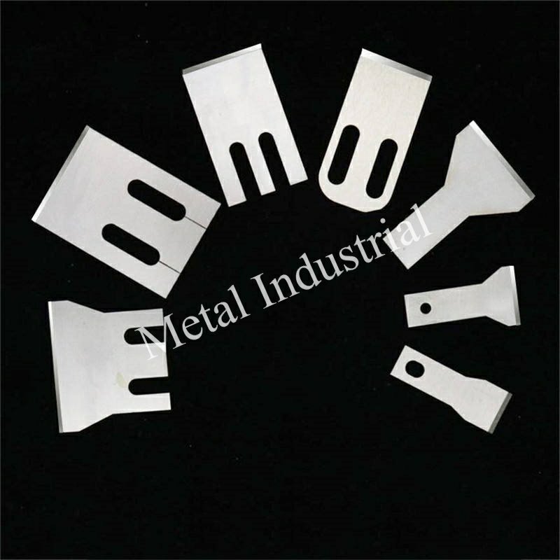
Schnellantwort: Das Verkleben von Messern bei der TPU-Unterwassergranulierung ist ein Systemproblem und kein reines Beschichtungsproblem. Die schnellste Lösung besteht darin, zuerst den Ursachenmechanismus zu beheben (Wiederherstellung der Schnittebenenstabilität und der Gleichmäßigkeit der Kühlung) und erst dann die Beschichtungen auszuwählen: DLC auf den Schneidkantenflächen für Härte und geringe Reibung, PTFE auf verschleißarmen Nicht-Schneidkantenflächen zur Reduzierung der Anhaftung. Der Einsatz von DLC ohne Korrektur von Ausrichtung oder thermischer Drift bringt selten dauerhaften Erfolg — erst validierte Betriebsfenster und eine KPI-Erfassung machen die Fortschritte nachhaltig.
Knife gumming in TPU underwater (die-face) pelletizing usually shows up the same way: pellet surfaces start to smear, tails (often called angel hair on the shop floor) increase, and fines climb until the dryer screens or water filters tell on you.
The frustrating part is that the knife itself is rarely the only variable. Adhesion is a system effect—melt rheology at the die exit, quench conditions, knife kinematics, and surface energy at the cutting interface all stack.
In Maxtor Metal’s knife work for water-ring and underwater systems, the fastest wins typically come from treating gumming as a mechanism + surface + window problem, not a “sharpen it harder” problem. If you’re also running a water-ring or underwater system that requires knife block qualification before commissioning, Maxtor Metal’s guide on runout, balance grade, and vibration acceptance for water-ring pelletizer knife blocks covers the full qualification framework that underpins stable die-face cutting — including the same contact and alignment disciplines discussed here.
This article frames why knife gumming spikes tails/fines in TPU underwater pelletizing knife gumming scenarios, what changes adhesion (temps, water, contact, coatings), and a practical path you can run: mechanisms → coatings → operating windows → validation/ROI.
The same logic generally applies to EVA and other high-viscosity, tacky elastomers where the cut has to be clean und the freshly cut surface has to be quenched fast.
Wichtigste Erkenntnis: If tails and fines rise together, assume the die-face cut is no longer a clean shear. Fix the mechanism (alignment/contact + quench), then pick coatings to reduce adhesion and slow re-wear.
Versagensmechanismen beim Messer-Verkleben bei der TPU-Unterwassergranulierung
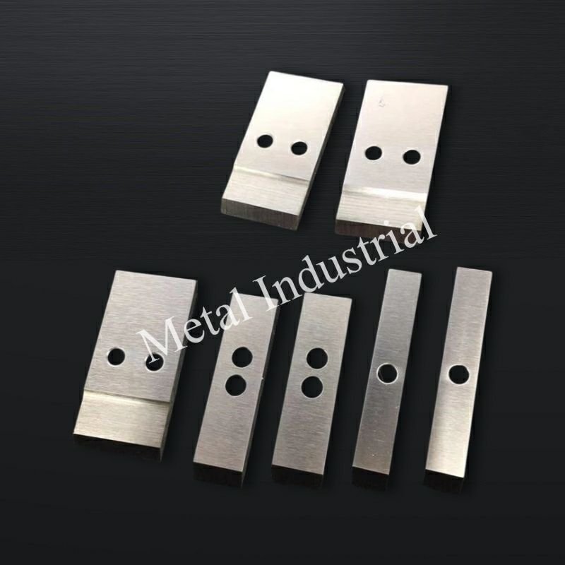
Thermal skinning and tack
TPU (and many EVA grades) can form a tacky surface “skin” at the die exit when the surface isn’t quenched quickly enough relative to throughput. That skin does two things that hurt pellet quality:
- It increases adhesive transfer to the knife edge and die face.
- It turns what should be a shear into a smear-and-tear event, which makes tails that later fracture into fines.
What usually pushes you into this failure mode:
- Melt/die too hot for the current recipe and output rate (surface stays soft at cut).
- Process water too hot or with insufficient velocity at the die face (quench lag).
- Start-up transients (die face not yet thermally stable; water loop drifting).
A helpful general overview of underwater pelletizing behavior and the role of rapid quenching is summarized in the MAAG plastics guidebook, Plastics Guidebook (MAAG Group, 2021 PDF).
Knife–die contact and alignment
A clean die-face cut depends on a stable cutting plane. Two shop-floor realities tend to break that:
- Knife edge wear (rounded edge increases contact area → more adhesion and heat).
- Die face wear / grooving (the melt catches and stretches rather than shears).
Misalignment amplifies both. If the knife track doesn’t stay concentric to the die face, you get uneven contact pressure: one side rubs (heat + smear), the other side undercuts (tails).
From a troubleshooting standpoint, Plastics Technology notes die/knife wear and setup as common upstream drivers when underwater pellet quality problems emerge (rather than downstream handling alone). See Mitigating and Troubleshooting Underwater Pelletizing Issues (Plastics Technology, 2020) for practical checks around die-face condition, cutter setup, and process stability.
Water chemistry and cavitation
Most gumming conversations focus on temperature, but water condition can quietly tip you into adhesion and unstable cutting:
- Hardness/scale can change boundary layers at the die face and disrupt local flow.
- Fines loading in the loop can create a “lapping slurry” that accelerates micro-wear at the knife edge and die face.
- Cavitation / aeration near the cutter housing can destabilize pressure and micro-cooling right where the cut happens.
You don’t need perfect water chemistry—you need consistent water chemistry and stable hydraulics. When gumming suddenly appears after “nothing changed,” check what did change in the water loop: filter DP, pump condition, entrained air, and heat-exchanger fouling.
Zusamenfassend: knife gumming in TPU underwater pelletizing is driven by three stacking variables — thermal skinning at the die exit, cutting-plane instability, and water-loop drift — and all three need to be under control before coatings can do their job.
Beschichtungen: PTFE vs. DLC
Coatings don’t fix a bad cutting plane. But once contact and quench are under control, coatings can do two valuable jobs:
- Reduce surface energy / friction at the interface so TPU is less likely to transfer and build up.
- Slow the re-wear that turns a good edge into a smeary edge.
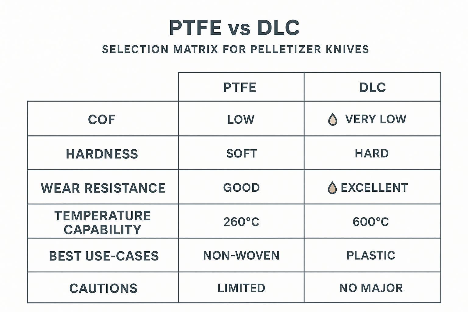
On pelletizer knives, PTFE and DLC behave very differently—so the right answer is usually “DLC where you cut, PTFE where you slide,” not an either/or.
PTFE traits and limits
PTFE topcoats are popular for tacky polymers because they’re non-stick and low-friction. In Maxtor Metal’s pelletizer blade programs for tacky elastomers, PTFE topcoats are specified as thin fluoropolymer layers for reducing adhesion on non-edge faces where contact pressure is low — typical thickness in the single-digit micron range.
Where PTFE helps most:
- Low-load regions where polymer transfer starts (e.g., non-cutting faces that see smearing).
- Short runs where adhesion dominates and abrasion is low.
Where PTFE usually disappoints:
- Primary cutting edge duty when contact pressure and micro-abrasion are high.
- Filled or contaminated streams where the coating wears through quickly.
In other words: PTFE is an anti-stick tool, not a wear armor.
DLC-PVD traits and variants
DLC (diamond-like carbon) is a family of thin carbon-based films deposited by PVD/PACVD routes. In practice, DLC’s value here is the combination of:
- Low friction (helps reduce transfer)
- High hardness (helps slow edge rounding)
In Maxtor Metal’s knife engineering for die-face systems, DLC (a-C:H variant) is the coating of choice for cutting-edge faces on TPU/EVA lines: PVD-deposited at micron scale, combining low surface energy with the hardness needed to slow edge rounding.
Two practical notes for engineers:
- DLC variants differ (hydrogenated vs doped types). Your coating vendor should be able to state the intended duty (sliding/adhesion vs high-impact).
- DLC is not magic against severe abrasive slurry; if you’re running heavy filler or dirty recycle, edge geometry and substrate selection still dominate.
For operations running dedicated WC–Co insert blocks on these same die-face systems, the interaction between insert hardness (HRA 88–92), braze integrity, and die-face contact pressure determines whether a DLC or PTFE coating can even perform as expected — see our guide on tungsten carbide insert grade selection, brazing, and contact control for underwater pelletizers.
For glass-fiber-loaded compounds where substrate selection is the primary decision — comparing M390 and CPM S90V on abrasive wear resistance, corrosion defense, and grindability in thin blade geometries — see our guide on PM stainless pelletizer blade grade selection under high glass-fiber wear.
If you need to reference how friction/wear claims are typically validated, the most common testing framework in tribology literature is pin-on-disk. The standard method is ASTM G99 (Wear Testing with a Pin-on-Disk Apparatus).
For DLC tribology fundamentals (why hydrogenated a-C:H films often deliver low friction and good wear resistance, and why environment/counterface matters), a concise open-access review can be found here: Tribological Properties of DLC Coatings in Model-Based and Real Contacts (open access, 2025).
Selection matrix by scenario
Use this as a pragmatic, line-side decision guide:
- TPU/EVA (tacky, low filler), gumming is the main problem
- Start with: polished cutting bevel + DLC on the cutting edge/working face
- Optional: PTFE on non-edge faces where transfer builds
- TPU with recipe changes and frequent start/stop
- Prioritize: DLC for durability + disciplined thermal window to avoid skinning
- Use PTFE sparingly where it can be maintained easily
- Filled EVA / contaminated recycle (abrasive water loop)
- Treat as wear-first: substrate + geometry + filtration
- DLC can help, but expect wear to be the limiting factor; PTFE will usually be short-lived
- If die face is already grooved
- Coatings won’t cure tails. Restore the cutting plane first (die refurbishment + alignment), then coat.
Zusamenfassend: DLC belongs on the cutting edge for hardness and friction control; PTFE belongs on non-edge faces for anti-stick — treating them as alternatives rather than complements is the most common coating selection mistake.
Betriebsfenster
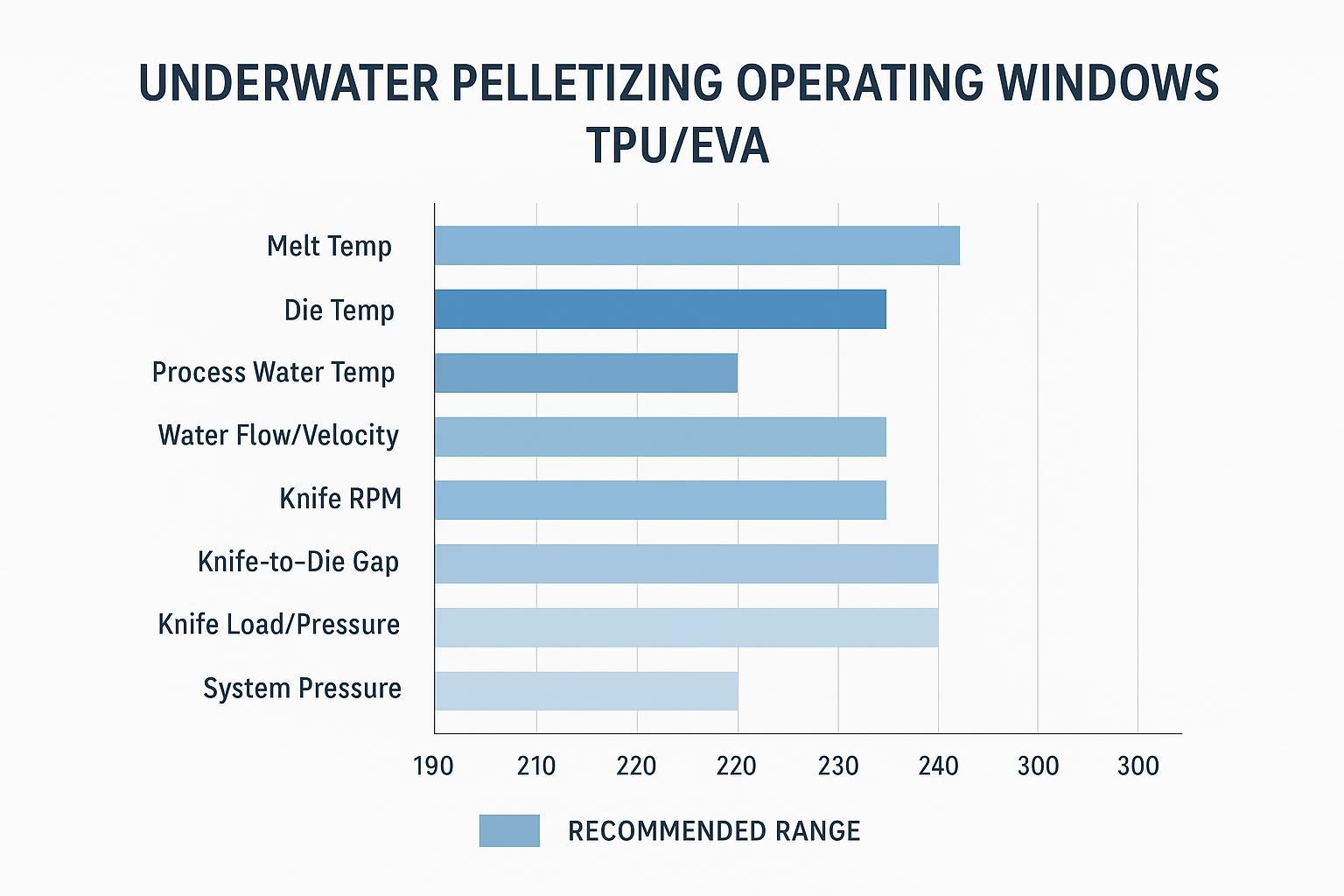
The goal of an “operating window” is not to find one magic setpoint. It’s to define a band where:
- the die exit is hot enough to avoid freeze-off
- the pellet surface quenches fast enough to avoid tack
- the knife sees stable contact without rubbing heat
Treat the ranges below as starting windows that must be validated on your specific die geometry, throughput, and recipe.
Thermal setpoints (TPU/EVA)
Practical heuristics that usually reduce gumming risk:
- Reduce peak melt temperature until torque/pressure stability starts to degrade, then step back up slightly.
- Halten die face temperature stable (avoid oscillation that alternates freeze-off and smear).
What failure looks like when you miss the window:
- Too hot: smear, stringing/tails, pellet-to-pellet sticking.
- Too cold: die freeze, hole blockage, surging, broken pellets (fines).
Water system: temp/flow/pH
Water has to do two jobs at once: quench the pellet surface and carry pellets away without letting them collide, smear, and agglomerate.
Best-practice checks:
- Water temperature: stabilize first; don’t tune knife load while water temperature is still drifting.
- Flow/velocity at die face: verify you have enough local velocity to sweep pellets away immediately after cut.
- Filtration and DP trend: log filter differential pressure and cleaning intervals; rising DP often correlates with rising fines.
- pH / hardness consistency: keep it consistent; sudden scale or corrosion products can destabilize the cut zone.
Knife setup, gap, pressure
For tacky elastomers, the knife setup is usually where small changes produce big quality swings.
Set-up discipline that prevents gumming from coming back:
- Knife-to-die gap / contact: aim for a stable cutting condition that’s consistent across the full rotation.
- Ausrichtung: verify concentricity and runout before “tuning” process temperatures.
- Knife speed vs throughput: tails often indicate a mismatch—either too slow for the melt flow, or unstable contact that prevents clean shear.
⚠️ Warnung: If you “solve” tails by increasing knife pressure until they disappear, you may simply be accelerating die-face wear. Validate with die-face inspection intervals, not only pellet appearance.
Applicability & prerequisites (read before copying the window)
The mechanism and troubleshooting logic in this guide is broadly transferable, but the exact operating window is not. Validate on your line if any of the following differ:
- TPU formulation (polyether vs polyester, hardness, additives), regrind %, or any mineral filler/pigment package.
- System type (underwater vs water-ring), cutter hub design, or die-plate hardface material.
- Water-loop condition (fines loading, filtration DP, scale/hardness) that can change boundary cooling at the die face.
- Die-face condition: if the die plate is already grooved, restore the cutting plane first—coatings may reduce adhesion but won’t remove mechanical tail formation.
Treat all temperature/flow/pressure bands as starting points and use the KPI logging method below to confirm stability.
Zusamenfassend: an operating window isn’t a single setpoint — it’s a validated band where die-exit quench, knife contact, and water-loop stability all overlap, and the only way to find it is to log KPIs through at least one recipe change and one start-up.
Validierung und ROI
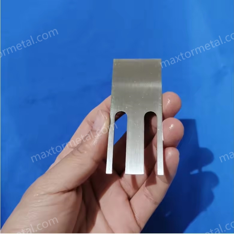
KPIs and data logging
If you want a change to stick across shifts and recipes, define KPIs that separate “looks better today” from “is actually under control.”
High-signal KPIs for underwater pelletizing gumming:
- Fines rate (by sieve cut or dust collection mass per ton)
- Tails/angel hair frequency (count per kg or visual standard + image log)
- Messerleben (hours or tons to regrind/replace)
- Die face condition (inspection score: groove depth, flatness, wear pattern)
- Ausfallzeit attributed to pelletizer cleaning / changeover
- Water loop indicators: temperature stability, filter DP trend, conductivity/pH trend
Log them with timestamps around:
- start-up
- recipe change
- water loop disturbances (filter change, pump swap, heat exchanger clean)
A/B trials and analysis
A controlled A/B trial is the fastest way to validate a coating change without turning the line into a moving target. Below is an anonymized example run on the same production line with a fixed process window so the result reflects surface behavior rather than setpoint drift.
Anonymized example (TPU underwater pelletizer, same recipe & operating window)
Notiz: This example is constructed from typical field patterns observed in pelletizer knife programs for tacky elastomers; it is not a single customer’s raw inspection record. Results will vary based on TPU formulation, filler content, die-face condition, and water-loop maturity.
- Resin: polyether-based TPU, no mineral filler, 15% regrind
- System: underwater pelletizer (equipment class similar to MAAG / Gala / BKG)
- Durchsatz: 4.5–5.2 t/h (held constant within ±2%)
- A (baseline knife): M2 tool steel + PTFE coating
- B (change): same substrate (M2) + DLC (a-C:H) coating
- Trial duration: 12 weeks total, 18 production batches, 126 pellet-sample sets
Key outcomes (A vs B)
Note on ranges: The KPI ranges above are observed operating ranges—the typical engineering range recorded across multiple production batches under the same recipe and fixed operating window during the trial period (not a statistical confidence interval).
- Fines: 0.9–1.2 wt% → 0.35–0.55 wt%
- Tails / stringers: 0.8–1.1% → 0.15–0.35%
- Knife cleaning frequency: every 10–14 h → every 30–40 h
- Knife life (to regrind): 150–180 h → 320–420 h
- Unplanned cleaning stops: ~5–6/month → ~1–2/month
- Pellet shape stability: late-run variability → stable over the run
What stayed fixed (so the comparison is meaningful)
- Water temperature: 58–62°C
- Water flow: within ±3%
- Melt temperature: 198–205°C
- Knife RPM: 2,700–2,900 rpm
- Knife contact pressure: OEM setpoint, not adjusted
- Die plate: same plate, no regrind
What the data suggests (mechanism, not marketing)
PTFE often reduces initial adhesion thanks to low surface energy and low friction, but under long duty cycles a transfer film can build and cleaning frequency rises. In this trial, DLC did not “eliminate” gumming; it delayed transfer-film formation and maintained a cleaner shear condition longer, which reduced tails/fines and extended usable knife life.
In practice, Maxtor Metal’s role in trials is usually strongest in test design and documentation discipline, because it reduces “unknown unknowns.” Define a one-page trial record that captures the variables engineers actually need to reproduce a result:
- Knife incoming checks: flatness, thickness parallelism, bevel angle, and edge roughness class
- Coating description: type (PTFE vs DLC), coating thickness target (micron-scale), and which surfaces are coated
- Changeover SOP: alignment checks and sign-offs
That kind of documentation makes A/B results easier to interpret when something changes (recipe, operator behavior, water-loop disturbances) and helps keep the trial focused on one variable at a time.
This is the standard Maxtor Metal uses when supporting customer trials — one variable changed, one dossier per knife set, and a defined inspection rhythm tied to tonnage.
Evidence & QC data to include in coating trials (what you can actually verify)
To strengthen interpretation (and avoid debates like “the resin changed”), include a short evidence pack with every knife/coating comparison:
- Coating specification: coating type (PTFE vs DLC), which surfaces are coated, and the target thickness range. Thickness matters because it affects both durability and surface behavior.
- Kantengeometrie: edge radius (or a defined sharpness class) and bevel angle. A rounded edge increases contact area and heat, which increases smearing and transfer.
- Surface finish: working-face roughness Ra/Rz before vs after the run (or before vs after cleaning). Roughness drift is a strong indicator of when a good shear becomes a smear.
- Material & heat treatment: substrate grade plus hardness/heat-treatment proof. A coating cannot compensate for insufficient substrate support under contact pressure.
- Traceability & inspection scope: batch/lot traceability and a clear checklist of what was inspected (flatness, thickness parallelism, runout, coating coverage).
These checks don’t “guarantee” performance, but they make A/B data defensible and reproducible across shifts and repeat orders.
Risk controls and SOPs
Once you identify a stable window, lock it in with a short SOP focused on the variables that actually drift:
- Start-up checklist: water temperature stable, flow verified, filter DP acceptable, die face warm-up complete.
- Setup checklist: verify alignment/runout, confirm knife condition, confirm target gap/contact method.
- Drift controls: what triggers an intervention (e.g., tails exceed X visual standard for Y minutes).
- Inspection rhythm: die face inspection interval tied to tonnage, not calendar time.
Zusamenfassend: a coating change is only validated when fines rate, tails frequency, and knife life are all tracked against a fixed process window — a visual check after one batch is not a trial.
FAQs:
F: Warum entstehen bei der TPU-Unterwassergranulierung plötzlich Fäden (Schwänze) und Feinanteile?
A: Meistens hat sich der Schnitt an der Lochplatte von einem sauberen Scherschnitt zu einem Verschmieren/Rausschlagen verändert. Ursache ist eine Kombination aus höherer Klebrigkeit (thermische Hautbildung) und verschlechterter Schnittgeometrie (Kantenverrundung, Lochplattenverschleiß oder Fehlausrichtung). Beheben Sie zuerst den Ursachenmechanismus — Kühlwasserstabilität und Anpressdruck zwischen Messer und Lochplatte —, bevor Sie von einer Harzveränderung ausgehen.
F: Wird „Engelshaar“ immer durch das Granuliermesser verursacht?
No. “Angel hair” is also commonly used for streamers created during pneumatic conveying from friction at elbows and high velocity. But if you see tails at the pellet exit and fines rise at the same time, the pelletizer cut zone is a likely source.
For conveying-related mechanisms, Plastics Technology discusses downstream causes in Keep Dust and Angel Hair Out of Your Process (Plastics Technology, 2017).
F: Sollte ich DLC oder PTFE wählen, um das Verkleben der Messer bei TPU zu stoppen?
A: Wenn die Schneidkante die Anhaftungsstelle ist, ist DLC in der Regel die bessere erste Wahl, da es geringe Reibung mit hoher Härte kombiniert und dazu beiträgt, dass die Kante länger „scharf“ bleibt. PTFE wird am besten als Antihaft-Deckschicht für verschleißärmere Bereiche eingesetzt; auf der Hauptschneidkante reibt es sich meist schnell ab.
F: Können Beschichtungen eine eingelaufene (eingefurchte) Lochplatte ausgleichen?
A: Nicht zuverlässig. Eine eingefurchte Lochplatte führt zu mechanischer Fadenbildung (die Schmelze wird entlang der Rille getrennt und gezog). Beschichtungen können die Anhaftung zwar vorübergehend reduzieren, stellen aber die Schnittebene nicht wieder her. Überarbeiten/schleifen Sie die Lochplatte nach und prüfen Sie zuerst die Ausrichtung.
F: Welche Prozesswassertemperatur ist bei der Unterwassergranulierung von TPU/EVA „zu heiß“?
A: Das hängt von der Rezeptur, dem Durchsatz und der Lochplattengeometrie ab. In der Praxis ist das Wasser „zu heiß“, wenn die Granulatoberflächen nach dem Schnitt klebrig bleiben und ein Materialübertrag (Verschmieren) auf das Messer stattfindet. Betrachten Sie die Wassertemperatur als Steuergröße und validieren Sie diese durch Verfolgen von Fäden/Feinanteilen und Reinigungsintervallen, anstatt sich auf einen einzelnen Zahlenwert zu verlassen.
F: Wie lässt sich am schnellsten validieren, ob ein Beschichtungswechsel erfolgreich war?
A: Führen Sie einen kontrollierten A/B-Test (auf derselben Anlage, mit derselben Rezeptur) durch und messen Sie Feinanteil, Fadenhäufigkeit und Standzeit der Messer über mindestens einen Anfahrvorgang und einen Durchsatz-/Rezepturwechsel. Vergleichen Sie sowohl die Streuung (Variabilität) als auch die Mittelwerte.
F: Funktioniert derselbe Ansatz auch bei EVA und anderen klebrigen Elastomeren?
A: Ja, der Mechanismus ist ähnlich: Eine schnelle Oberflächenkühlung (Abschreckung) kombiniert mit einer stabilen Schnittgeometrie reduziert die Anhaftung, und die Auswahl von DLC oder PTFE folgt derselben Logik. Was sich ändert, ist das exakte Betriebsfenster (Temperaturen, Messergeschwindigkeit/-anpressdruck) und wie empfindlich die Rezeptur auf die Hautbildung reagiert.
F: Wie kann ich das Verkleben der Messer reduzieren, ohne den Verschleiß der Lochplatte zu erhöhen?
A: Vermeiden Sie es, Fäden (Schwänze) rein durch Erhöhung des Messer-Anpressdrucks zu „lösen“. Stellen Sie stattdessen die Ausrichtung wieder her, definieren Sie ein stabiles thermisches und Wassertemperatur-Betriebsfenster und verwenden Sie eine haftungsarme Oberfläche (häufig DLC auf den Arbeitsflächen). Überprüfen Sie dies anschließend durch Inspektion der Verschleißmuster auf der Lochplatte in festen Tonnage-Intervallen.
Fazit
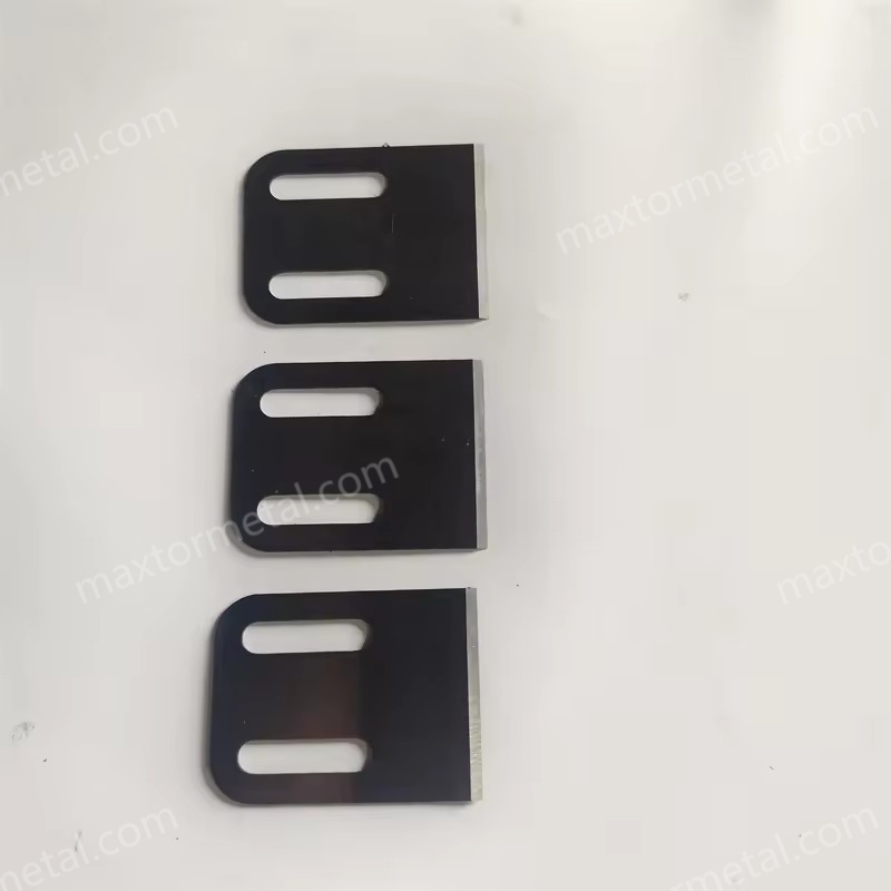
Bei der TPU-Unterwassergranulierung ist der Einsatz von DLC auf den Arbeitsflächen der Messer (insbesondere an der Schneidkante) in Kombination mit diszipliniert eingehaltenen Betriebsfenstern einer der zuverlässigsten Wege, Fäden/Feinanteile zu reduzieren und die Standzeit der Messer zu verlängern. PTFE bleibt als Antihaft-Deckschicht in verschleißarmen Bereichen nützlich, ist jedoch selten die beste Strategie für die Hauptschneidkante.
Die praktische Reihenfolge der Arbeitsschritte ist stets dieselbe: Versagensmechanismus bestätigen (thermische Klebrigkeit + Stabilität der Schnittebene), Beschichtung basierend auf dem Verschleiß-/Anhaftungsszenario auswählen, Einstellfenster für Wasser/Temperatur/Messer festlegen und mittels KPI-Erfassung sowie einem einfachen A/B-Test validieren.
For the full range of pelletizer knife materials, coating options (including PTFE and DLC thin films), and QC checkpoints Maxtor Metal applies to these blades, see the plastic pelletizer blade page — a useful starting point for aligning spec requirements with your procurement or quality team. The mechanism-first sequence — alignment and quench before coatings, coatings before pressure adjustment — is what separates a durable fix from one that holds for a batch and then drifts.
Autor
Nancy Wu is a Senior Manufacturing Engineer in Production Engineering (PE) at Maxtor Metal with 12 years of experience in industrial blade manufacturing and application support. Her work spans the machining characteristics of common blade materials (D2, M2, H13, powder metallurgy steels, and carbide), coating selection and performance in polymer processing, and high-precision CNC grinding program development. She holds SME–CMfgE, PMP, Six Sigma Black Belt, and ASM International certifications.

 English
  Spanish
  Italian
  French
  Portuguese
  Russian
  German
  Arabic
  Hindi
Hindi  Vietnamese
  Indonesian
  Japanese
  Korean