

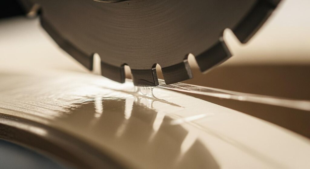
Cuando el adhesivo comienza a acumularse en las cuchillas de corte circular, la primera señal raras veces es drástica. Los bordes cortados se vuelven ligeramente pegajosos. La geometría del rollo se desvía. La calidad del borde se degrada antes de que el supervisor de turno pueda identificar la causa. Para cuando se ha formado un depósito de polímero visible —un filo recrecido (BUE)— en la cara de la cuchilla, esta ya lleva horas funcionando a menor rendimiento.
Esta guía cubre los mecanismos detrás de la acumulación de adhesivo en cuchillas circulares de corte por cizalla, los parámetros de ajuste que la suprimen o aceleran, y las selecciones de materiales y mantenimiento que diferencian las líneas de cinta con alto OEE de aquellas que pasan más tiempo solucionando problemas que funcionando. Los ingenieros y gerentes de producción que trabajan con cintas PSA, películas protectoras y sustratos recubiertos de adhesivo encontrarán las ventanas de parámetros, comparaciones de recubrimientos y la lógica diagnóstica directamente aplicables a nivel de máquina.
Para circular knives and slitting blades used in adhesive-sensitive applications, understanding buildup physics is prerequisite to specifying the right tool and the right conditions.
La guía práctica a continuación se basa en los más de 15 años de experiencia práctica de Maxtor Metal en la fabricación y reafilado de cuchillas circulares de corte de precisión, así como en datos de campo de líneas de películas protectoras y cintas sensibles al adhesivo. Cuando una cifra específica provenga de una prueba de cliente o de una prueba publicada, se mencionará la fuente para que pueda evaluarla en función de sus propias condiciones.
Causas termomecánicas
Heat–Contact Feedback Loop
The accumulation sequence begins at the shear point. As the upper circular blade and lower female ring engage the web, the adhesive layer — whether solvent-acrylic, hot-melt, or UV-cured PSA — is sheared and stretched at the cut face. At that moment, adhesive polymer chains with sufficient tack can bond to the blade surface.
The deposit begins small: microscopic polymer patches on the blade bevel. But buildup changes the effective cutting geometry, which increases drag, which generates more frictional heat. Heat reduces PSA cohesive strength and raises surface tack. That in turn accelerates transfer rate, reinforcing the cycle.
Conclusión clave: Adhesive buildup is self-reinforcing. Once a polymer patch forms, local heat spikes raise tack and promote faster accumulation. Interrupting the loop early — through geometry, coating, or cleaning — is far less costly than recovering from a fully glazed blade.
This cycle is compounded at higher line speeds, where the blade’s heat dissipation rate cannot keep pace with frictional input, and at higher line tensions, which press the web harder against the knife edge.
Blade Condition and Geometry Effects
A sharp, correctly finished blade edge initiates a clean shear fracture through the adhesive layer. A worn or improperly finished edge drags rather than cuts — stretching adhesive strands across the blade face instead of severing them. Every worn micron of edge radius increases the contact zone and the likelihood of adhesive transfer.
Bevel geometry matters independently of sharpness. A double-hollow-ground bevel reduces the land area in contact with the cut face, lowering the surface available for adhesive to wet and bond. A conventional flat bevel keeps a larger land in continuous contact with the material — which is why double-hollow or compound-bevel grinds are often specified for high-tack PSA applications.
For a rigidity-led framework on choosing between single, double, and compound bevel geometries — including included-angle selection by substrate family and the trade-off between tip structural support and adhesive contact-land area — see Biseles simples, dobles y compuestos para cuchillos de corte circulares..
Surface roughness is equally critical. An edge finish target of Ra ≤ 0.10 µm (mirror-level polish) significantly reduces adhesive anchor points compared to a standard-ground finish in the Ra 0.2–0.4 µm range. Rough surfaces provide micro-pockets where polymer chains can mechanically interlock, even when the adhesion thermodynamics would otherwise be marginal.
Adhesive Rheology and Environment
Not all PSA systems present equal risk. Rubber-based PSAs tend to be more cohesive, which helps them separate cleanly from the blade. Acrylic PSAs — particularly those formulated for aggressive peel strength — have lower cohesive strength relative to their tack, making them more prone to cohesive failure at the slit face and subsequent blade transfer. Hot-melt PSAs are temperature-sensitive: ambient shop floor temperature above 25 °C can meaningfully increase their deposition rate.
Humidity matters less for most PSA tapes than for hygroscopic paper stocks, but electrostatic charge — generated during unwinding and slitting — can attract fine adhesive particles to the blade face independently of the mechanical cutting process. Facilities running at relative humidity below 40% will encounter elevated static activity.
Parámetros de ajuste que controlan la acumulación
Overlap, Cant Angle, Side Load
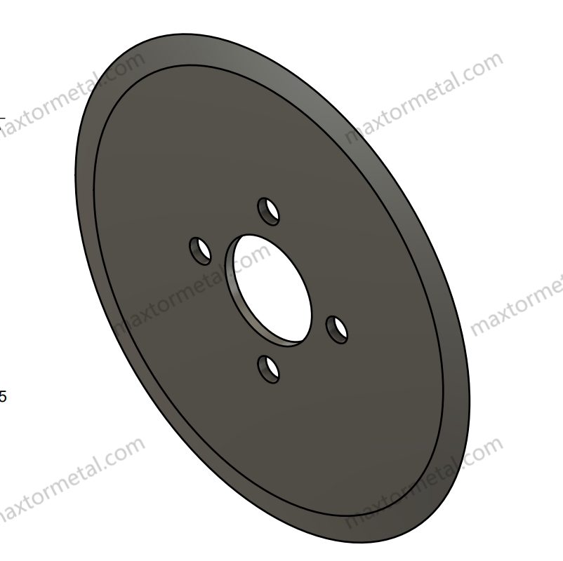
These three parameters define the cutting engagement geometry. All three affect heat generation and adhesive deposition rate, and all three have narrow optimal windows for PSA-sensitive applications.
Superposición is the vertical penetration of the upper blade past the tangent surface of the lower ring. Published shear-slitting references generally recommend starting at approximately 0.030 in. (0.76 mm) for most film and label materials, then adjusting from there. For PSA-coated webs, the practical starting window is 0.4–0.75 mm: enough to produce a full shear fracture without excess rubbing on the blade face. Over-overlap increases heat and contact time; under-overlap leaves adhesive strands uncut, which then string and deposit on the knife.
Cant angle — the angular tilt of the upper blade relative to the web — creates the progressive shear action that completes the cut. In established shear-slitting practice, the typical cant range for flexible laminates and tape constructions is 0.25°–0.75°, with 0.50° the most commonly used starting point. Higher angles increase edge contact and should only be used when the material fiber structure specifically requires it.
Carga lateral is the lateral force holding the upper blade in contact with the lower ring. Typical pneumatic side-load values sit in the 2–7 lbf range and should not vary by more than about 0.5 lbf during a run. For adhesive-sensitive applications, target the lower end: 2–5 lbf. This minimizes rubbing friction at the blade-ring interface without sacrificing cutting stability.
The setup sequence matters: set cant angle first and lock it, then set overlap conservatively, then add the minimum side load that maintains stable contact.
For a DOE-based analysis of how overlap depth and side clearance interact across substrate families — with Pareto trade-off data between edge quality and knife life that covers adhesive-coated webs — see Optimización de la profundidad de solapamiento y la holgura lateral de las cuchillas circulares..
These three parameter windows — overlap 0.4–0.75 mm, cant angle 0.25°–0.75°, side load 2–5 lbf — represent the commissioning baseline Maxtor Metal’s application engineering team uses when qualifying circular shear-slitting knives for PSA tape and protective film lines. Staying within these windows from the first production run is the single most effective way to prevent the heat–contact feedback loop from establishing itself.
For a detailed treatment of how spring-loaded preload interacts with overlap and cant angle during shear slitting setup — and how to lock in stable contact geometry before adding coating and lubrication — see Sistema de corte por cizallamiento con resorte y tolerancia cero: control de solapamiento, ángulo de inclinación y precarga..
Web Tension and Speed Stability
Web tension that varies cycle-to-cycle creates micro-fluctuations in blade engagement force, translating directly into adhesive transfer variation. In precision slitting, the usual target is to hold tension accuracy within 1% at constant speed. A general starting point for most PSA tape constructions is ≤10% of the web material’s tensile yield strength, calibrated downward for softer constructions.
Speed changes are an underappreciated variable. Acceleration and deceleration phases put the blade through a brief high-friction transient as the cutting geometry settles. If buildup is concentrated near reel starts or ends, line speed ramp control is the most probable cause.
Blade Temperature as a Leading Indicator
Blade surface temperature is the best real-time indicator of accumulation risk. A fixed-mount IR pyrometer aimed at the knife face gives process engineers a leading signal that precedes visible buildup by 10–30 minutes on most tape constructions. Establish a baseline temperature for a clean blade at production speed, and treat any sustained rise of 8–12 °C above that baseline as an early warning to inspect and clean.
Field Case: Label-Stock Line Cutting Cleaning Intervals by 75%
The following example draws on published converting industry field reports and aligns with results Maxtor Metal’s technical team has observed across label-converting and PSA tape projects. It is included to illustrate the magnitude of improvement achievable when geometry, surface finish, and coating are optimized together.
A representative example comes from the label-converting segment, where adhesive buildup is the dominant cause of unplanned blade changes. On a line slitting pressure-sensitive label stock, operators reported the classic symptoms: slit edges turning tacky within a few hours, dust and adhesive smearing on the blade face, and cleaning stops that kept getting shorter. Rather than replacing blades blindly, the documented solution path runs through geometry and surface treatment together: change the blade bevel geometry, switch to polished top blades finished to a 1–2 RMS (≈ 0.025–0.05 µm Ra) surface, add an oil wick or wiper, and apply a special low-energy coating to both top and bottom blades.
Field reports from this approach point to one of the few quantified figures available in the public domain: the special top-and-bottom blade coating reduced adhesive build-up by as much as 75%, and these blades commonly ran 7 to 8 hours between cleanings on label stock.
Translated to the shop floor, this is the difference between cleaning a blade every shift and cleaning it roughly once per shift with margin to spare. The measures map directly to the mechanisms in this guide — polished finish (fewer anchor points), wiper/wick (boundary lubrication), and coating (low surface energy) each attack a different link in the heat–contact–tack loop.
Selección de materiales y recubrimientos
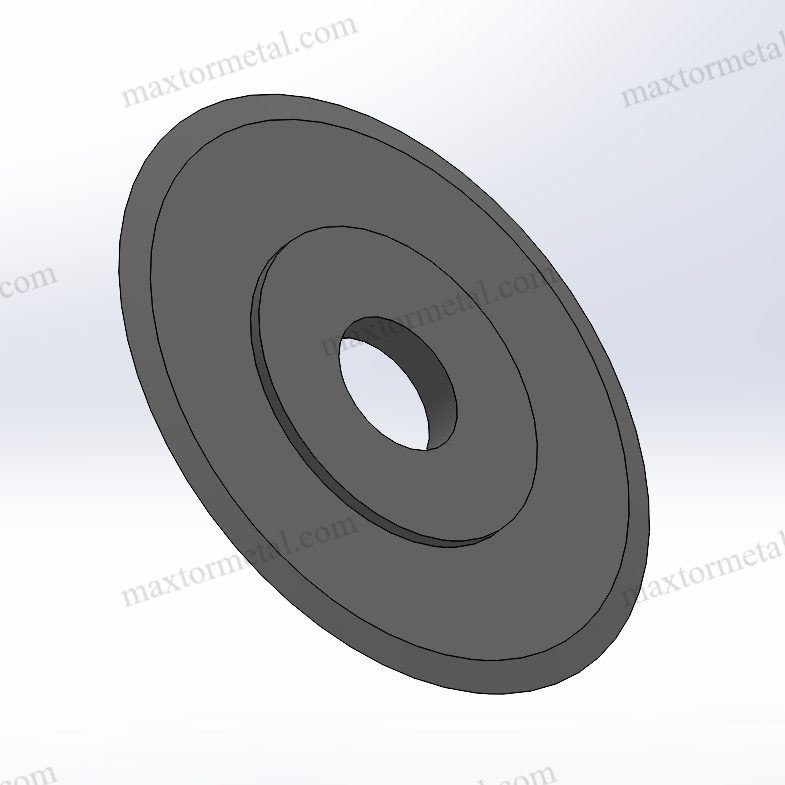
Blade Substrates and Edge Finishes
The substrate steel determines achievable hardness, the surface finish attainable after grinding, and the adhesion performance of any subsequent coating. High-speed steel (HSS) grades such as M2 (typically 62–64 HRC after heat treatment) support the Ra ≤ 0.10 µm finish targets required for PSA applications and provide adequate toughness for thin film slitting. High-chromium, high-carbon tool steels achieve similar hardness but require careful edge geometry management to avoid micro-chipping on flexible film constructions.
Solid carbide circular blades are generally over-engineered for soft PSA films and can suffer edge micro-chipping when the substrate lacks the compliance to absorb vibration loads. They are better matched to metallic foil or hard-film slitting.
Specify the edge finish in your blade procurement documents. Superfinishing to Ra ≤ 0.10 µm — achievable by lapping or fine-grit honing after grinding — measurably reduces adhesive deposition rate compared to a standard-ground edge in the Ra 0.2–0.4 µm range. Do not leave this to vendor default.
The role of blade flank Ra in controlling friction and particulate generation — including the carbide microstructure requirements for achieving and retaining a mirror finish — is covered in detail in Análisis de causa raíz de la generación de polvo de corte longitudinal: Ra del flanco de la cuchilla, microestructura del carburo y tolerancias de ajuste.
When you write the specification, anchor the verification to recognized standards rather than to a supplier’s word. Hardness is conventionally verified by the Rockwell method per ASTM E18 (or Vickers/micro-hardness for thin or coated edges), while dimensional and geometric tolerances are commonly controlled through ISO 2768-1 for general linear dimensions or ASME Y14.5 where GD&T is used. Naming the test method in the purchase order removes ambiguity about how compliance is demonstrated.
Low-Adhesion Coatings (DLC/TiN/CrN)
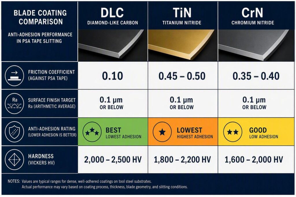
The three coatings most widely applied to circular slitting blades for PSA applications — DLC (diamond-like carbon), CrN (chromium nitride), and TiN (titanium nitride) — differ significantly in their tribological behavior against adhesives.
Published tribological data from Structure and Tribological Properties of TiN/DLC, CrN/DLC and Related Hybrid Coatings (Materials, 2025) reports friction coefficients (µ) at 10 N load of approximately 0.10 for DLC, 0.35–0.40 for CrN, y 0.45–0.50 for TiN. Lower friction at the blade-adhesive interface correlates directly with lower adhesive transfer rate.
The friction coefficients below are sourced from peer-reviewed tribological testing (Materials, 2025) and major coating supplier datasheets. These values inform Maxtor Metal’s coating recommendation sequence for PSA slitting applications.
| Revestimiento | Friction coefficient (µ) | Anti-adhesion for PSA | Hardness (approx. HV) | Best fit |
|---|---|---|---|---|
| Contenido descargable | ~0.10 | Excelente | ≥ 1,500 | High-tack acrylic PSA, aggressive thin films |
| CrN | ~0.35–0.40 | Bien | ~1,800 | General PSA, label stock, rubber-based adhesives |
| Estaño | ~0.45–0.50 | Moderado | ~2,300 | Wear resistance priority; not first choice for anti-stick |
DLC is the first choice where adhesive buildup is the dominant failure mode. Its ultra-low friction and chemical inertness prevent polymer chain bonding far more effectively than nitride coatings. CrN is a practical middle ground when DLC is not available or cost is constrained. TiN should not be selected primarily for PSA anti-adhesion performance, though it remains appropriate for harder, non-sticky substrate slitting where wear resistance is the priority.
The counterintuitive part: hardness does not predict anti-stick performance
There is a widespread procurement assumption that the harder the coating, the better it resists adhesive pickup. Published coating data does not support that assumption, and the reason is rooted in the buildup mechanism itself rather than in wear physics.
Consider the property sets from two major coating suppliers. Ionbond’s published coating specifications list dry friction against steel and microhardness in the following ranges: TiN around µ ≈ 0.5 at 2,500–3,100 HV, CrN around µ ≈ 0.5–0.55 at 2,100–3,000 HV, y certain DLC / metal-doped DLC (MeDLC) systems around µ ≈ 0.2 at a comparatively lower 1,000–1,800 HV. Oerlikon’s published BALINIT DLC data follows the same pattern from the opposite direction: a typical BALINIT DLC coating sits at roughly 15–25 GPa (≈ 1,500–2,500 HV) with a dry friction coefficient of 0.1–0.2 against steel, and Oerlikon explicitly attributes the coating’s benefit in plastics and adhesive-contact applications to its low friction and inert surface chemistry, which reduce adhesive wear, sticking, and deposit formation.
Read those two data sets together and the engineering conclusion writes itself: the hardest of the three coatings (TiN) has the highest friction, and the coating with the best anti-stick reputation (DLC) is not the hardest — it is the lowest-friction and most chemically inert. For a PSA slitting application, the failure mode is not abrasive wear of the blade; it is adhesive transfer, and adhesive transfer is governed by friction, surface energy, and heat — not by hardness.
This matters because hardness is the property most often written into a purchase specification and the easiest for a supplier to advertise. It is also the wrong control variable for this specific problem. Picking a coating on hardness alone is a reasonable strategy for cutting abrasive-filled or glass-fiber-reinforced substrates, where the dominant wear mechanism is abrasion. On a PSA tape line, it mis-targets the physics.
Coating selection for PSA slitting should not be based on hardness alone. Friction coefficient, surface chemistry, edge geometry, and thermal behavior must be evaluated together, because the buildup loop is thermal and chemical — heat softens the adhesive, softened adhesive transfers, transferred adhesive increases friction, and increased friction generates more heat. A coating that wins on hardness but loses on friction is feeding the loop, not interrupting it.
The practical implication for spec sheets: when comparing coatings for an adhesive-sensitive line, ask the supplier for friction coefficient and surface energy data alongside hardness, and evaluate them in that order of priority. If a supplier can only quote hardness, the data set is incomplete for this application.
Coating adhesion to the substrate is as important as coating chemistry. PVD (physical vapor deposition) processes produce dense, well-bonded films. Verify with your blade supplier that coating thickness is uniform across the blade face — edge coverage failures are a common cause of early delamination in slitting service.
For a deeper comparison of DLC and PTFE coating behavior across wear-limited and transfer-limited failure modes — including how each coating ages under repeated cleaning cycles — see Guía de Selección de Revestimientos DLC vs PTFE para Cuchillas de Corte: Desgaste vs Transferencia.
Geometry Matching to PSA and Substrates
Coating and substrate choices work in combination with edge geometry, not as a substitute for it. A DLC-coated blade run with an over-overlap setup will still accumulate adhesive faster than an optimally configured uncoated blade. The sequence is always: correct geometry first, then surface treatment.
For thin PSA films (< 60 µm total construction), a compound bevel or double-hollow grind reduces the contact land to the minimum needed for structural integrity. For thicker, stiffer constructions — foam tapes, heavy-gauge protective film — a standard bevel with appropriate side clearance provides the rigidity needed to prevent chatter.
Mantenimiento y control de la electricidad estática
Cleaning Intervals and Approved Solvents
Cleaning intervals should be set by processed-meter count per SKU, not by calendar time. For aggressive acrylic PSA applications, intervals as short as 2,000–3,000 m are common; for light label stock or rubber-based PSA, 5,000–10,000 m intervals are often workable.
Solvent selection requires chemical compatibility checking against both the PSA adhesive type and the blade coating. Isopropyl alcohol (IPA) is the most widely compatible starting choice for acrylic PSA residue on DLC and CrN coated blades. Methyl ethyl ketone (MEK) is more aggressive and effective against hot-melt residue but requires ventilation controls and compatibility verification with DLC coatings — some DLC chemistries can be affected by ketone solvents over repeated exposure. Avoid chlorinated solvents unless explicitly validated by the coating supplier. Ultrasonic cleaning in an appropriate solution is effective for off-machine blade cleaning without direct edge contact.
Always wipe in the direction away from the cutting edge. Wiping toward the edge can roll adhesive debris into the bevel and introduce abrasive particles that score the polished face.
Static Neutralization and Upstream Hygiene
Static charge on the web amplifies adhesive particle transfer to the blade face independently of cutting dynamics. On film slitting lines running at 150 m/min or above, triboelectric charge generated during unwinding can reach several kilovolts. Active ionizer bars mounted at the web entry point — upstream of the slitting station — suppress this charge before it reaches the cutting nip.
Upstream hygiene is equally important. Adhesive squeeze-out at web edges, overspray from coating stations, and contaminated idler rolls all contribute to blade contamination on many lines. Audit the full material path from unwind to slitting station as part of any systematic contamination reduction program. A clean web entering the slitting station is worth more than any blade coating.
Lubrication and Anti-Stick Aids
Controlled blade lubrication is among the most effective interventions for adhesive-sensitive applications. The two most common delivery methods are:
- Felt wick systems: Lubricated felt pads mounted in the blade holder contact the rotating blade face continuously. Saturation with silicone oil or a purpose-formulated non-transfer lubricant keeps the face conditioned throughout the run.
- Oil-mist systems: A fine silicone oil mist applied to the blade face creates a thin boundary layer that prevents adhesive bonding without adding visible contamination to the slit edge.
Check lubricant compatibility with the downstream use of the slit material. Silicone contamination is problematic for automotive tapes and some medical constructions where adhesion to painted or primed surfaces is required.
Solución de problemas y trazabilidad de control de calidad (QC)
Symptom-to-Action Diagnostic Logic
| Síntoma | Most likely cause | First action |
|---|---|---|
| Tacky slit edge | BUE on blade face | Stop, clean blade; check overlap and blade temperature |
| Edge quality degrading mid-reel | Heat buildup | Check IR temperature baseline; reduce line speed 5–10%; inspect edge |
| Visible polymer deposit on bevel | Accumulated PSA transfer | Clean with approved solvent; inspect edge for wear; verify cant angle |
| Adhesive stringing across slit | Under-overlap or worn edge | Increase overlap in 0.1 mm increments; check edge sharpness |
| Buildup concentrated at reel start | Acceleration phase heat surge | Reduce speed ramp rate; inspect tension control at startup |
| Buildup concentrated at reel end | Reduced tension at unwind core | Taper tension profile; calibrate dancer / load cell |
| Sudden increase in cleaning frequency | Upstream contamination or coating delamination | Audit material path for squeeze-out; inspect blade coating integrity |
Consejo profesional: Keep a per-SKU blade temperature log. When a specific tape construction shows temperature excursions above its clean-blade baseline, it often signals an incoming batch with elevated adhesive tack or a process drift — identifiable before the first off-spec roll ships.
Layered Diagnostic Decision Logic
The table above maps a single symptom to a first action — useful for firefighting. But most recurring buildup problems are not a single fault; they are a chain, and the fastest way to a durable fix is to walk the chain in a deliberate order. The sequence below is the diagnostic logic Maxtor Metal’s application engineering team applies to adhesive-sensitive slitting problems: identify the symptom, test the condition, act, and — critically — if the action does not resolve it, move to the next branch rather than repeating the same first action.
Step 1 — Confirm the deposit is actually adhesive, not wear debris. Before adjusting anything, establish what is on the blade. A transparent, tacky film that wipes off with solvent is adhesive transfer. A dark, hard, adherent layer is more likely coating wear or oxidized residue and points to a completely different corrective path. Cleaning and checking the wipe residue takes two minutes and prevents a whole class of misdiagnosis.
- If it wipes off and is tacky → continue to Step 2.
- If it is dark, hard, and resists solvent → stop tuning geometry; inspect the coating for delamination and verify substrate heat treatment.
Step 2 — Is buildup uniform along the run, or concentrated at reel start/end? The spatial pattern points to the mechanism.
- Concentrated at reel start → acceleration-phase heat surge. Reduce the speed ramp rate and inspect tension control at startup.
- Concentrated at reel end → tension decay at the unwind core as the roll diameter shrinks. Taper the tension profile and calibrate the dancer/load cell.
- Uniform across the run → a steady-state problem (geometry, coating, or material), not a transient. Continue to Step 3.
Step 3 — Walk the parameter window before touching the blade. A uniform steady-state buildup is almost always a parameter issue until proven otherwise, and parameters are cheaper to change than blades.
- Controlar overlap first: is it inside 0.4–0.75 mm for this construction? Over-overlap adds heat and contact time; under-overlap strings adhesive onto the knife.
- Then check cant angle: is it inside 0.25°–0.75°?
- Then check side load: is it in the 2–5 lbf window and stable to ±0.5 lbf?
- If any parameter is out of window → correct it, run a 300–450 m verification pass, and re-measure. Do not change two parameters at once — you will not know which one fixed it.
- If all parameters are in window → continue to Step 4.
Step 4 — Check temperature behavior against baseline. With parameters ruled out, temperature tells you whether the problem is thermal or material. Compare the current blade temperature against the clean-blade baseline for that SKU.
- Temperature rising but material unchanged → suspect blade degradation (edge wear, coating loss). Measure the edge radius and inspect the coating under magnification.
- Temperature stable but adhesion still occurring → suspect the incoming material: adhesive tack, coat weight, or cure variation between batches. Quarantine the suspect lot and compare its certificate with the previously good lot.
- Temperature spiking intermittently → suspect mechanical: chatter, vibration, or a misaligned anvil. Check runout and contact pattern.
For a measurement-first approach to diagnosing axial and radial TIR — including cold-to-hot drift protocols and the defect signatures each runout mode produces on adhesive-sensitive film lines — see Desviación axial, TIR dinámico y calidad del borde de la ranura.
When runout or chatter is confirmed as a contributing factor, see Cómo detener los cortes serpenteantes en el corte de film: Lista de comprobación del sistema for a full bearing, alignment, and tension diagnosis sequence.
Step 5 — Escalate to a controlled comparison only after Steps 1–4. If the problem persists with confirmed-clean material, in-window parameters, and stable temperature, you have reached the point where a blade-to-blade comparison is justified. Use the gravimetric test protocol in the next section to compare the current blade against an alternative (coating, finish, or geometry) under otherwise identical conditions. This is the last step, not the first, because it is the most time-consuming — and because Steps 1–4 eliminate the most common causes before you commit test time.
The value of the layered sequence is that it prevents the most expensive diagnostic error in slitting: changing the blade when the problem was a parameter, or changing parameters when the problem was a material batch. Walking the chain in order costs almost nothing and resolves the majority of buildup complaints before anyone touches a knife.
A Measurable Test Protocol for Adhesive Accumulation
Most buildup debates stay subjective — “the blade looks gluey.” A published patent test method offers a repeatable way to turn that into data. In U.S. Patent 6,423,392 / EP 1 159 368, PSA label constructions were slit with 3 pairs of stainless-steel blades and anvils at a nominal 0.5° blade-to-anvil cant angle y 0.0625 in. overlap, at a constant web speed of 400 ft/min (≈ 122 m/min) and constant side load. After each 2,500 ft (≈ 762 m) roll, the adhesive residue on the blades and anvils was removed and weighed — a gravimetric method that quantifies build-up directly instead of rating it low/medium/high (US 6,423,392).
You can adapt this into a qualification sequence that fits a normal production run. At each checkpoint, capture a small, consistent data set:
| Distance run (equivalent) | Record |
|---|---|
| 0 m (baseline) | Blade-face photo; blade temperature; motor current / cutting-load proxy |
| 150 m | Same set + adhesive transfer area estimate |
| 300 m | Same set |
| 450 m | Same set |
| 600 m | Same set |
| 750 m | Same set; weigh scraped residue (gravimetric); note time to next required cleaning |
Running this sequence once per blade type — uncoated vs. DLC vs. CrN, or standard finish vs. mirror finish — gives you a curve rather than a single data point, and turns “which blade lasts longer” into a defensible comparison. It also separates blade-origin problems from setup-origin problems, which is the core diagnostic question in the next section.
Recording Parameters and Blade Lot Data
Consistent QC traceability is the foundation for distinguishing blade-origin problems from setup-origin problems. Each blade should be documented at receipt with the material grade, heat treatment batch, surface finish measurement (Ra), and coating lot. On multi-knife setups, coating thickness batch-to-batch consistency also feeds into spacer stack-up error — small per-knife dimensional variation accumulates into axial shift that alters the calibrated shear clearance. For the stack-up math governing this, see Control de la tolerancia de espesor acumulativo en el corte con múltiples cuchillas.
When blade performance deviates — through accelerated buildup, edge chipping, or dimensional drift — lot data makes it possible to determine whether the issue is systemic across a production batch or isolated to a specific machine setup.
Material verification through the blade supply chain is one area where traceability has direct operational value. An EN 10204 3.1 material test certificate (MTC) is a lot-specific inspection document: it reports the actual measured chemical and mechanical results for the specific heat or batch supplied, and is signed by an inspection representative organizationally independent of production. That is what distinguishes it from a generic 2.1 declaration — the numbers belong to the material you received, not to a catalog.
Maxtor Metal supplies full MTCs per EN 10204 3.1 with blade lots, covering chemical composition, hardness, and dimensional tolerances. This supports cross-referencing incoming blade quality against line performance data — a useful control for facilities managing adhesive-sensitive runs where blade-to-blade consistency directly affects OEE metrics. Buyers who need external, third-party validation of those results should note that EN 10204 3.2 adds precisely that independent verification layer; specify 3.2 when supply-chain risk or regulatory exposure warrants it.
OEE/TCO Impact and SLA Considerations
Adhesive accumulation affects OEE through three channels: unplanned stoppages for blade cleaning, scheduled preventive cleaning events that consume available production time, and quality losses from off-spec slit edges. A line running 10-minute cleaning events every 2,500 m at 200 m/min loses approximately 0.8% of available production time per cleaning cycle — before accounting for inspection and re-qualification time.
TCO calculations for blade selection should account for:
- Coating premium vs. cleaning labor: A DLC-coated blade may cost 2–3× a standard blade but can reduce cleaning frequency by 40–60% on aggressive PSA applications, shifting TCO decisively in its favor across a 12-month operating window.
- SLA and reject rate: A single adhesive-contaminated roll per shift creates disproportionate rework costs on pressure-sensitive and optical film constructions, where adhesive defects are often detectable only at the customer’s laminating or die-cutting step.
- Regrind intervals: Frequent cleaning without adequate solvent-coating compatibility control can accelerate coating degradation, forcing earlier regrind cycles. Documenting the relationship between cleaning frequency, solvent type, and coating life is the basis for accurate regrind cost modelling.
- Bore fit and arbor precision: A blade that meets all coating and finish specifications but sits on an under-toleranced bore will generate intermittent contact-pressure variation — which drives adhesive transfer in the same way excess overlap does, but is invisible to setup parameter audits. For the ISO 286 fit selection logic that controls assembled TIR at the arbor level, see Tolerancia y excentricidad del orificio central: Optimización de los ajustes ISO 286 para cuchillas de corte de alta velocidad.
FAQs
P: ¿Por qué se acumula adhesivo en las cuchillas circulares de corte?
R: La transferencia de adhesivo comienza en el punto de corte (cizalla) donde la cuchilla entra en contacto con la capa de PSA. El calor friccional en la interfaz entre la cuchilla y el sustrato ablanda el adhesivo, reduce su resistencia cohesiva y hace que sea más probable que se transfiera a la cara de la cuchilla. Una vez que se forma un depósito de polímero, este altera la geometría de corte, aumenta la fricción y acelera la generación adicional de calor, creando un ciclo de autorrefuerzo. La combinación de una rugosidad superficial de la cuchilla superior a Ra 0.10 µm, parámetros de ajuste subóptimos (sobre-solapamiento, carga lateral excesiva) y una química de adhesivo de alta pegajosidad impulsa la acumulación más severa.
P: ¿Qué ajustes de solapamiento y ángulo de inclinación reducen la acumulación de adhesivo?
R: Para la mayoría de las aplicaciones de cintas PSA y películas protectoras, comience con un solapamiento (overlap) de 0.4–0.75 mm y un ángulo de inclinación (cant angle) de 0.25°–0.75°, siendo 0.50° el punto de partida más común para estructuras flexibles. Utilice siempre los valores mínimos de parámetros que produzcan un corte limpio: el exceso de solapamiento aumenta el tiempo de contacto en la cara de la cuchilla y la generación de calor. Una carga lateral de 2–5 lbf (extremo inferior del rango típico) reduce la fricción en la interfaz cuchilla-contrafilo sin comprometer la estabilidad del corte.
P: ¿Qué recubrimiento de cuchilla es mejor para cortar cinta PSA?
R: El DLC (carbono tipo diamante) ofrece el coeficiente de fricción más bajo (µ ≈ 0.10) y la mayor resistencia a la adhesión de polímeros entre las tres opciones comunes. El CrN (µ ≈ 0.35–0.40) es una alternativa práctica cuando el DLC no está disponible o el presupuesto es limitado. El TiN (µ ≈ 0.45–0.50) ofrece mayor dureza pero un rendimiento antiadherente más débil, por lo que no es la primera opción para aplicaciones antiadherentes de PSA.
P: ¿Con qué frecuencia se deben limpiar las cuchillas de corte al cortar cinta adhesiva?
R: Establezca la frecuencia de limpieza según el recuento de metros procesados por SKU, y no por tiempo de calendario. Para PSA acrílico de alta adherencia (high-tack), lo típico es entre 2,000 y 3,000 m entre limpiezas. Para material de etiquetas más ligero o PSA a base de caucho, a menudo se pueden alcanzar de 5,000 a 10,000 m. Monitorear la temperatura de la cara de la cuchilla con un pirómetro IR fijo proporciona una señal de advertencia temprana: un aumento sostenido de 8–12 °C por encima de la línea base de la cuchilla limpia indica que es hora de inspeccionar y limpiar antes de que se forme una acumulación visible.
P: ¿Qué disolventes son seguros para limpiar los residuos de PSA de las cuchillas de corte con recubrimiento?
R: El alcohol isopropílico (IPA) es el disolvente más compatible de forma general para los residuos de PSA acrílico en cuchillas con recubrimiento DLC y CrN. La metiletilcetona (MEK) es más agresiva y eficaz contra los residuos de PSA termofusible (hot-melt), pero requiere control de ventilación y verificación de compatibilidad con las químicas de recubrimiento específicas. Evite los disolventes clorados a menos que el proveedor del recubrimiento los haya validado explícitamente. Limpie siempre en direccióncontraria al filo de corte para evitar que los residuos se introduzcan en el chaflán (bisel).
P: ¿Cómo contribuye la carga estática a la contaminación de las cuchillas durante el corte de cinta?
R: La carga triboeléctrica generada durante el desbobinado del sustrato y el contacto con los rodillos guía puede alcanzar niveles de kilovoltios en las líneas de corte de película a velocidades de producción. Este potencial electrostático atrae partículas finas de adhesivo y polvo hacia la cara de la cuchilla, independientemente del proceso de corte mecánico. Las barras ionizantes activas montadas aguas arriba de la zona de corte (nip) son el control estándar. Mantener la humedad relativa de la planta entre el 40% y el 60% también reduce la generación de electricidad estática en la trayectoria de la banda.
P: ¿Cuál es el caso de TCO (costo total de propiedad) para las cuchillas con recubrimiento DLC en comparación con las no recubiertas en el corte de PSA?
R: Los recubrimientos DLC suelen costar entre 2 y 3 veces más que las cuchillas sin recubrimiento o con recubrimiento TiN. En aplicaciones de PSA, el DLC permite reducir la frecuencia de limpieza entre un 40% y un 60%, lo que disminuye la mano de obra, el consumo de disolventes y las pérdidas de OEE por paradas breves. En una línea con paradas de limpieza de 10 minutos cada 2,500 m, una reducción del 50% en la frecuencia equivale a un ~0.4% adicional de tiempo de actividad diario. Cuando un solo rollo contaminado causa el rechazo del cliente, la prevención de pérdidas por calidad refuerza aún más la viabilidad del TCO.
P: ¿Cómo puedo saber si un problema de acumulación de adhesivo proviene de la cuchilla o de la configuración de la máquina?
R: Comience con la trazabilidad del lote de cuchillas: verifique el certificado de prueba de material para el grado del sustrato, la dureza y el acabado superficial. Si la cuchilla cumple con las especificaciones, audite los parámetros de configuración (solapamiento, ángulo de inclinación, carga lateral y tensión del sustrato) frente al rango documentado para ese SKU. Si la configuración está en rango, inspeccione el lote de material entrante en busca de variaciones en la pegajosidad del adhesivo, peso de recubrimiento y consistencia de curado. El registro de la temperatura de la cuchilla por SKU proporciona la señal de diagnóstico más clara: si la temperatura ha aumentado en relación con la línea base sin un cambio de configuración, o bien la cuchilla se ha degradado o las características del material entrante han cambiado.
Conclusión
La acumulación de adhesivo en las cuchillas circulares de corte es impulsada por un bucle de retroalimentación de calor-contacto-adhesividad que, una vez establecido, se acelera. Las palancas disponibles para los equipos de producción operan en tres niveles: mecánica (solapamiento, ángulo de inclinación, carga lateral, tensión del material), materiales (sustrato, acabado del filo, selección de recubrimiento) y mantenimiento (intervalo de limpieza, disolvente, lubricación, control estático).
Las ventanas de parámetros — solapamiento de 0.4–0.75 mm, ángulo de inclinación de 0.25°–0.75°, carga lateral de 2–5 lbf, tensión de la banda mantenida estable en ≤10% del límite elástico — representan el rango operativo práctico para la mayoría de las construcciones de cintas PSA y películas protectoras. Dentro de ese rango, un recubrimiento de DLC o CrN sobre un sustrato pulido a espejo (Ra ≤ 0.10 µm), respaldado por una lubricación programada con mecha de fieltro y limpieza basada en intervalos, ofrece la tasa de acumulación total de adhesivo más baja posible con las herramientas actuales.
Para una implementación por fases, comience documentando la temperatura base de la cuchilla y el intervalo de limpieza por SKU. Esos datos identifican qué aplicaciones generan una carga de mantenimiento desproporcionada y justifican las mejoras de recubrimiento dirigidas. Añada trazabilidad de MTC por lote al recibir la cuchilla para cerrar el bucle de retroalimentación entre la calidad de la herramienta entrante y el rendimiento de la línea.
When selecting or qualifying circular knives for adhesive-sensitive slitting applications, align the specification — steel grade, heat treatment, surface finish, and coating — to the adhesive chemistry and construction thickness of the primary SKUs you run. A correctly specified blade, properly maintained and documented, will outperform the best troubleshooting protocol applied to an incorrectly specified one.
Referencias y lecturas adicionales
The guidance in this article draws on the following standards, peer-reviewed research, and patent literature. Each is included so readers can verify the underlying figures and apply the methods to their own operations.
Standards and certification
- ASTM E18 — Standard Test Methods for Rockwell Hardness of Metallic Materials. The reference test method for verifying blade substrate hardness. Official ASTM page; full text is available for purchase.
- ASTM D1894 — Standard Test Method for Static and Kinetic Coefficients of Friction of Plastic Film and Sheeting. Establishes the friction measurement basis for film and tape surfaces. Official ASTM page; full text is available for purchase.
- ISO 2768-1 — General tolerances, Part 1: Tolerances for linear and angular dimensions without individual tolerance indications. Commonly used for general blade dimensional control. Official ISO catalogue page; full text is available for purchase.
- ASME Y14.5 — Dimensioning and Tolerancing. Applied where blade drawings use GD&T. Official ASME page; full text is available for purchase.
- EN 10204 — Metallic products — Types of inspection documents. Defines the 2.1, 2.2, 3.1, and 3.2 certificate types; Type 3.1 reports batch-specific test results signed by an inspection representative independent of production. Official BSI page for BS EN 10204:2004 (the official English-language version of EN 10204:2004, issued by CEN).
Investigación revisada por pares
- Materiales (MDPI, 2025) — “Structure and Tribological Properties of TiN/DLC, CrN/DLC and Related Hybrid Coatings” — friction coefficients for DLC, CrN, and TiN coatings.
- Chemical Engineering & Technology (Wiley, 2023) — “Tribological Performances of Diamond-Like Carbon Coatings” — hardness and friction values for commercial DLC coating systems.
Coating supplier technical data (for friction vs. hardness comparison)
- Ionbond — Tribobond 42 (DLC) coating data: microhardness 2,000–2,800 HV, friction vs. steel < 0.1. Manufacturer-published coating specification.
- Ionbond — Ionbond 01 (TiN-based) coating data: friction vs. steel (dry) ≈ 0.55. Manufacturer-published coating specification.
- Oerlikon Balzers — Carbon-based BALINIT DLC coating series: coating hardness ≈ 15–25 GPa and coefficient of friction 0.1–0.2 (dry, against steel), with low-friction, inert surface chemistry reducing adhesive wear, sticking, and deposits. Official Oerlikon product literature.
Patent literature
- U.S. Patent 6,423,392 / EP 1 159 368 — "Pressure-sensitive adhesive compositions and pressure-sensitive adhesive label constructions exhibiting low adhesive residue in printers" — describes the slitting test and gravimetric residue-weighing method referenced in the measurement protocol.
Sobre el autor
Jerry Chu — Especialista en soporte técnico, servicio posventa, Maxtor Metal
Jerry Chu is a technical support specialist with 10 years of hands-on experience in industrial cutting applications, spanning papermaking, plastics granulation, metal slitting, and wood processing. He works directly on customer sites to resolve practical cutting problems — edge burrs, excessive dust, adhesive build-up, and premature blade wear — and translates those field observations into blade specifications that hold up in production. He holds the PMP (Project Management Professional) and CMRP (Certified Maintenance & Reliability Professional) credentials.
The field guidance in this article reflects the practical troubleshooting perspective Jerry brings to adhesive-sensitive slitting applications, where a correctly specified blade and a disciplined maintenance routine consistently outperform reactive problem-solving.

 English
  Spanish
  Italian
  French
  Portuguese
  Russian
  German
  Arabic
  Hindi
Hindi  Vietnamese
  Indonesian
  Japanese
  Korean