

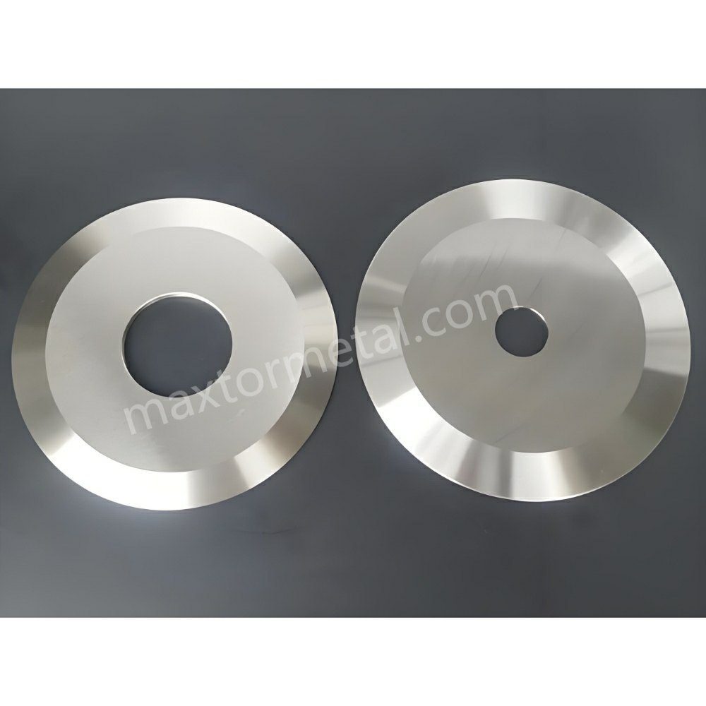
Los cortes en serpentina (también llamados desviación o deriva de la línea de corte) ocurren cuando el borde cortado no mantiene una trayectoria recta y repetible: los carriles "caminan", oscilan o se desplazan gradualmente, de modo que las capas del rollo rebobinado ya no quedan centradas. Trátelo como un problema de estabilidad de todo el sistema de corte y bobinado, no como un defecto de un solo parámetro.
Esta lista de verificación refleja la forma en que la mayoría de los equipos de mantenimiento y procesos resuelven este problema en el campo. Se basa en la secuencia de diagnóstico que utiliza el equipo de ingeniería de campo de Maxtor Metal al solucionar problemas de por qué un corte que se ve bien durante la configuración se vuelve inestable a alta velocidad.
Conclusión clave: Si los cortes de serpiente cambian con la velocidad, la construcción de rodadura o la posición en el carril, comience por aislar de dónde proviene la fuerza lateral (fuerzas del cuchillo vs. mecánica de la red vs. aire/estática) antes de empezar a “girar perillas”.”
Este enfoque de diagnóstico centrado en los sistemas es el marco que el equipo de ingeniería de aplicaciones de Maxtor Metal aplica al brindar soporte a los clientes en líneas de corte de film y no tejidos, donde la deriva de los carriles ha resistido las soluciones de una sola variable.
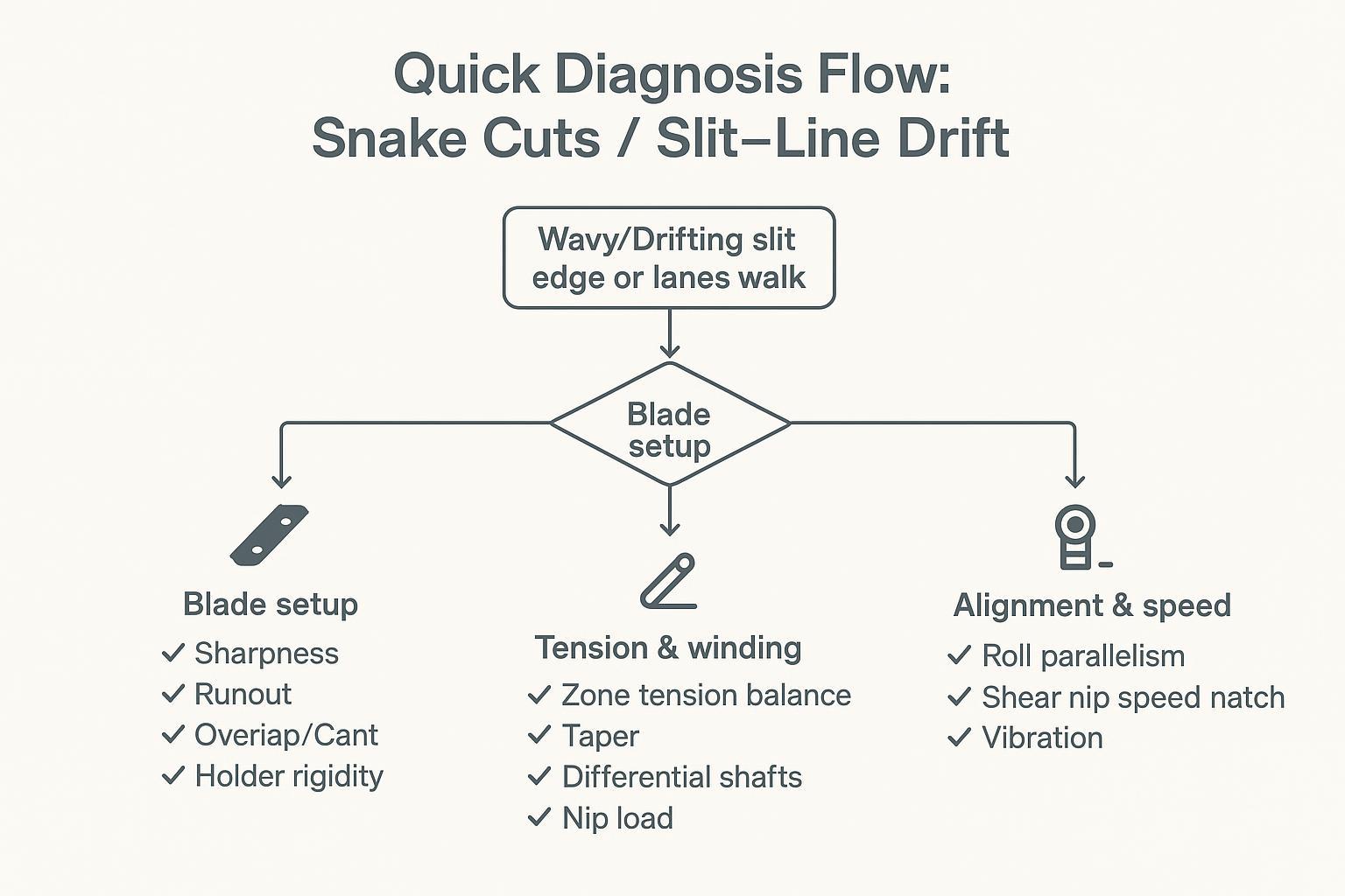
Flujo de diagnóstico rápido
Cuándo sospechar de problemas con las cuchillas
- El problema es específico del carril (uno o dos carriles se desvían mientras los vecinos mantienen su posición).
- Comienza el derrape justo en el punto de corte, incluso a baja velocidad.
- Recientemente cambiaste los cuchillos, los espaciadores, los soportes o moviste la pila de cuchillos.
- La deriva tiene un carácter repetitivo de "una vez por revolución" (a menudo vinculado a un desajuste o a un asiento desalineado).
Comprobaciones rápidas:
- Verifique la limpieza de la pila de cuchillos (que no haya restos de película, adhesivo ni rebabas en las caras).
- Verificación de la excentricidad del indicador de cuadrante en las caras del eje/cuchilla en los carriles que se desvían.
- Confirme que la superposición/acoplamiento y la inclinación/trayectoria se encuentren dentro del rango esperado para el método de corte.
¿Cuándo sospechar de tensión/enrollamiento?
- La deriva empeora a medida que El diámetro del rollo aumenta.
- El defecto “se mueve” de carril en carril con posición central o cambios en la torreta.
- Verás telescópico, bordes sueltos o variación de dureza entre carriles.
- El derrape mejora inmediatamente cuando reducir velocidad o cambiar los puntos de ajuste de tensión.
Comprobaciones rápidas:
- Comparar las tensiones de las zonas de desenrollado/a mitad de la tela/rebobinado (reales frente al valor de ajuste).
- Verifique el comportamiento de la tensión de conicidad a lo largo del proceso de fabricación del rollo.
- Confirme que el deslizamiento del eje diferencial funciona correctamente en cada carril (sin elementos bloqueados).
Cuándo sospechar de alineación/velocidad
- La deriva empeora después del mantenimiento, el reemplazo de los cojinetes o un golpe o sobrecarga.
- La red sigue bien la trayectoria río arriba, y luego cambia de dirección tras un giro o un pequeño tirón.
- Usted escucha/siente vibraciones, ve marcas de patrones o experimenta oscilación en la guía de bordes.
Comprobaciones rápidas:
- Compruebe el paralelismo de los rodillos y el equilibrio de los dientes de contacto; busque desviaciones evidentes o desgaste irregular.
- Igualación de velocidades en el punto de corte (velocidad de la cuchilla frente a velocidad de la banda).
- Estado de los rodamientos y vibraciones (temperatura, ruido, espectro si está disponible).
Matriz de causas raíz de corte de serpiente
Utilice esta tabla como referencia rápida para la evaluación inicial antes de ajustar cualquier configuración.
| Patrón de síntomas | subsistema más probable | Primera comprobación |
|---|---|---|
| Derrape específico del carril, comienza en el cuchillo, presente a baja velocidad | Cuchilla / soporte | TIR en las caras del árbol y del cuchillo en los carriles afectados; comparar con los carriles estables. |
| La deriva empeora a medida que aumenta el balanceo; mejora cuando disminuye la velocidad. | Bobinado de tensión/diferencial | Tensión real frente a tensión de consigna en cada zona; par de deslizamiento diferencial del eje |
| La deriva apareció después de un evento de mantenimiento o mecánico. | Alineación / rodamiento | Paralelismo de rodadura; espectro de temperatura y vibración del rodamiento |
| La deriva varía según el lote de rollos principal o la posición en el carril (borde o centro). | Perfil del material/calibre | Variación del espesor transversal de la banda; correlación de la dureza entre carriles con la posición del rodillo principal. |
| La deriva empeora a mayor velocidad y mejora al aumentar la presión de apoyo. | Arrastre de aire / estático | Prueba de reducción de velocidad; comprobación de continuidad de la salida del ionizador y de la conexión a tierra. |
Configuración de la cuchilla y tolerancias
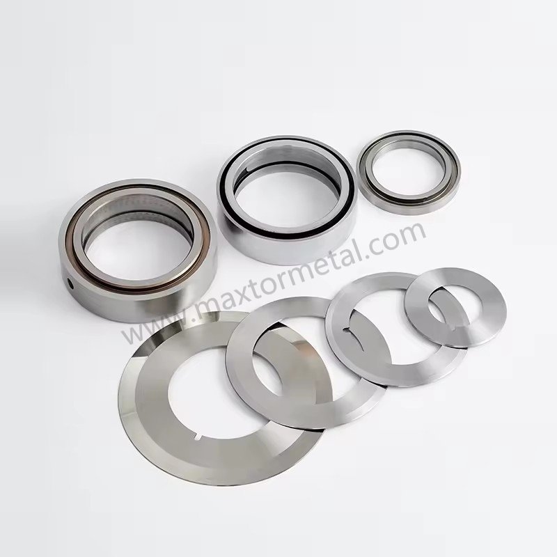
Nitidez, desviación, superposición, inclinación
Los cortes de serpiente suelen comenzar como una pequeña desviación lateral repetible. En muchas líneas, la forma más rápida de comprobar o refutar la desviación "impulsada por el filo" es medir la desviación en los puntos clave.
- NitidezUn filo desafilado aumenta la fuerza de corte y puede "guiar" la banda, especialmente en películas delgadas a velocidades más altas.
- Recorrido (TIR): Compruebe los hombros del eje, las caras del espaciador y las caras de la cuchilla, no solo un punto conveniente. Mantenga la desviación total indicada dentro de ≤0,025–0,050 mm (0,001–0,002 pulgadas) en todo el conjunto. La inspección de entrada de Maxtor Metal registra la TIR tanto en la superficie de contacto de la cara de la cuchilla como en la del eje por lote, de modo que las mediciones de campo se pueden comparar con los datos documentados de fábrica cuando aparece un problema de deriva después de un cambio de cuchilla. Para un tratamiento de la TIR axial y radial que prioriza la medición, incluidos los protocolos de verificación de deriva de frío a caliente y los mecanismos de defecto que produce cada modo de desviación, consulte EjeCalidad de la excentricidad, TIR dinámico y borde de ranura.
- Superposición / compromiso: Establezca la superposición al valor estable mínimo para su método y material (normalmente comenzando en 0,5–1,2 mm / 0,020–0,045 pulgadas (para el corte de película por cizallamiento estándar). El exceso de solapamiento puede enmascarar temporalmente un problema mecánico mientras se añade calor y carga lateral. Para películas delgadas (PE/PP/PET <50 μm), el equipo de ingeniería de campo de Maxtor Metal utiliza 0,50–0,75 mm como ventana inicial y la ajusta en función de la calidad del borde y la tendencia de la fuerza de corte. Para un análisis completo de cómo interactúan el solapamiento, el ángulo de inclinación y la precarga con resorte durante la configuración, consulte Sistema de corte por cizallamiento con resorte y tolerancia cero: control de solapamiento, ángulo de inclinación y precarga..
- Tranvía: Mantenga los ángulos de inclinación dentro de las especificaciones del fabricante (normalmente 0.25°–0.5°Si la máquina no está correctamente calibrada, se puede obtener un corte que parezca aceptable durante la configuración, pero que se vuelva inestable a medida que las fuerzas aumentan con la velocidad.
Para referencias de corte por cizallamiento, la Guía de referencia de corte longitudinal de DIENES es una base útil para saber cómo se trata la superposición como una variable controlada en lugar de una configuración de "cuanto más, mejor" (ver Guía de referencia de corte DIENES, 2.ª ed. (PDF)).
Para líneas donde la elección del recubrimiento también está bajo revisión, en particular si los recubrimientos de DLC o PTFE afectan el comportamiento de deriva y los intervalos de limpieza, consulte Guía de Selección de Revestimientos DLC vs PTFE para Cuchillas de Corte: Desgaste vs Transferencia.
Rigidez del soporte y carga lateral
Incluso con buenos cuchillos, un soporte flexible o una pila que permita la variación de la carga lateral provocará que se desvíen a gran velocidad.
Cheques que suelen dar resultado:
- Confirme que los soportes estén colocados planos y sujetos de manera uniforme a lo largo de toda la pila.
- Inspeccione si hay marcas de rozamiento, desgaste o rozamiento que indiquen micromovimientos bajo carga.
- Verifique que los espaciadores no estén generando una "acumulación de tolerancias" que provoque una desviación lateral (especialmente en montajes de múltiples carriles).
- Esté atento a los aumentos de carga lateral que se correlacionen con la acumulación de rodillos o el aumento de temperatura.
Los problemas de apilamiento de espaciadores a menudo se remontan a la precisión del ajuste del orificio. Para conocer la lógica de selección de ajuste ISO 286 que establece la precisión de posicionamiento del orificio al mandril, y cómo se verifica el TIR ensamblado antes de que un conjunto de cuchillas entre en producción, consulte Tolerancia y excentricidad del orificio central: Optimización de los ajustes ISO 286 para cuchillas de corte de alta velocidad.
La calidad del suministro influye en la estabilidad de la configuración más de lo que la mayoría de los equipos tienen en cuenta. Los lotes de cuchillos con dureza inconsistente o variación dimensional introducen una variable que parece un problema de configuración, pero que no responde a los ajustes de configuración.
El sistema Maxtor Metal documenta la dureza, la inspección dimensional y los registros de trazabilidad de lotes/coladas para todos los envíos de cuchillas de corte circular; de esta manera, cuando aparece un problema de desviación después de un cambio de cuchilla, la investigación puede comenzar con datos verificados del lote entrante en lugar de trabajar hacia atrás a partir de los síntomas.
Para proyectos OEM/ODM en los que las cuchillas deben coincidir con los soportes, ejes o planos de ingeniería existentes, Maxtor Metal ofrece soporte completo para especificaciones personalizadas, evitando así que un simple reemplazo de cuchilla se convierta en un ciclo de prueba y error de geometría.
Para conocer el cálculo de acumulación que rige cómo la variación del grosor de cada cuchilla se acumula en un error de ancho de ranura en una configuración de múltiples carriles, y una disciplina de ajuste de espaciadores para minimizar el desplazamiento axial en el cambio, consulte Control de la tolerancia de espesor acumulativo en el corte con múltiples cuchillas.
Opciones de tijeras, navajas y trituración
Adapta el método de corte al material y al defecto que estás intentando corregir:
Antes de seleccionar el método de corte, la geometría del bisel también debe coincidir con la rigidez del sustrato: un bisel simple que funciona en una película delgada de PE se comportará de manera diferente en laminados de PET. Para un marco de selección basado en la rigidez que abarca perfiles de bisel simple, doble y compuesto, consulte Biseles simples, dobles y compuestos para cuchillos de corte circulares..
- corte por cizallaIdeal cuando se requiere una calidad de canto uniforme y se puede mantener la geometría (desviación, solapamiento, carga lateral). Tiende a ser estable cuando la base mecánica es correcta.
- Rebanadas con navajaSencillo y limpio en películas delgadas, pero sensible al estado de la cuchilla, la posición de la ranura y la estabilidad de la banda. La posición de la ranura es importante: si la ranura es demasiado poco profunda en relación con el grosor de la banda, la cuchilla se desvía lateralmente bajo la tensión de la banda y la trayectoria de corte varía con los cambios de velocidad de la banda; si es demasiado profunda, la banda se adhiere a los bordes de la ranura y el seguimiento se vuelve sensible a cualquier asimetría de tensión lateral. La deriva también puede aparecer rápidamente cuando la banda se desliza sobre una película de aire a alta velocidad, o cuando la estática aumenta la adhesión lateral a las superficies guía.
- Corte por aplastamientoPuede ser indulgente en algunas configuraciones, pero también puede amplificar la inestabilidad cuando las condiciones de la goma/yunque varían o cuando se acumula calor.
| Categoría de sustrato/película | Método recomendado | Ventaja clave | Factor de riesgo de deriva |
|---|---|---|---|
| Poliolefina delgada (BOPP/PE) | Navaja en ranura / Cizalla | Borde de corte limpio, mínimo polvo | Desviación de la pala, flotación del aire |
| Rígido / Alto módulo (PET, PVC) | corte por cizalla | Geometría de corte precisa, bordes limpios | Desviación de la cuchilla, desalineación de la inclinación |
| Películas gruesas / laminadas | Cizallamiento / Aplastamiento pesado | Alta capacidad de fuerza cortante | Variación de carga lateral, desgaste de la hoja |
Para un marco basado en DOE que mapea cómo la profundidad de superposición y la holgura lateral interactúan en estas categorías de sustrato, incluido un modelo de compensación de Pareto entre la calidad del filo y la vida útil de la cuchilla, consulte Optimización de la profundidad de solapamiento y la holgura lateral de las cuchillas circulares..
Si observa cortes en forma de serpiente únicamente en ciertas referencias de productos, reevalúe si el método coincide con el espesor de la película, el módulo, el coeficiente de fricción y el rango de velocidad.
Control de tensión y bobinado
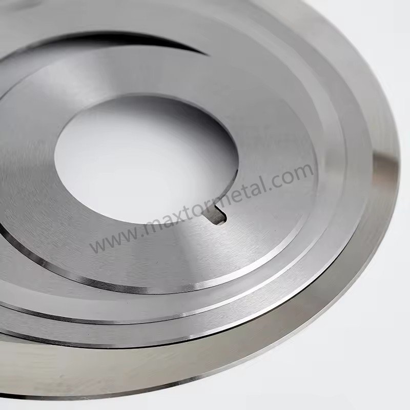
Puntos de ajuste y perfiles
La tensión no es solo un número, sino un perfil que se desarrolla a lo largo de las zonas y del tiempo. Un recorrido de ranura estable depende de un estado de tensión estable en la red.
Reglas prácticas que siguen vigentes:
- Mantenga la tensión estable en todo momento. desenrollar → procesar intervalo → rebobinar, y verificar las mediciones reales de la celda de carga con respecto a los puntos de ajuste del controlador. Cambios de tensión que excedan ±5%–8% Las desviaciones del objetivo suelen ser suficientes para provocar un deslizamiento lateral de la red y dar lugar a una deriva en la línea de corte. El equipo de campo de Maxtor Metal utiliza esta banda de ±5%–8% como umbral de alerta al revisar los registros de tensión durante las investigaciones posteriores a la deriva en las líneas de los clientes.
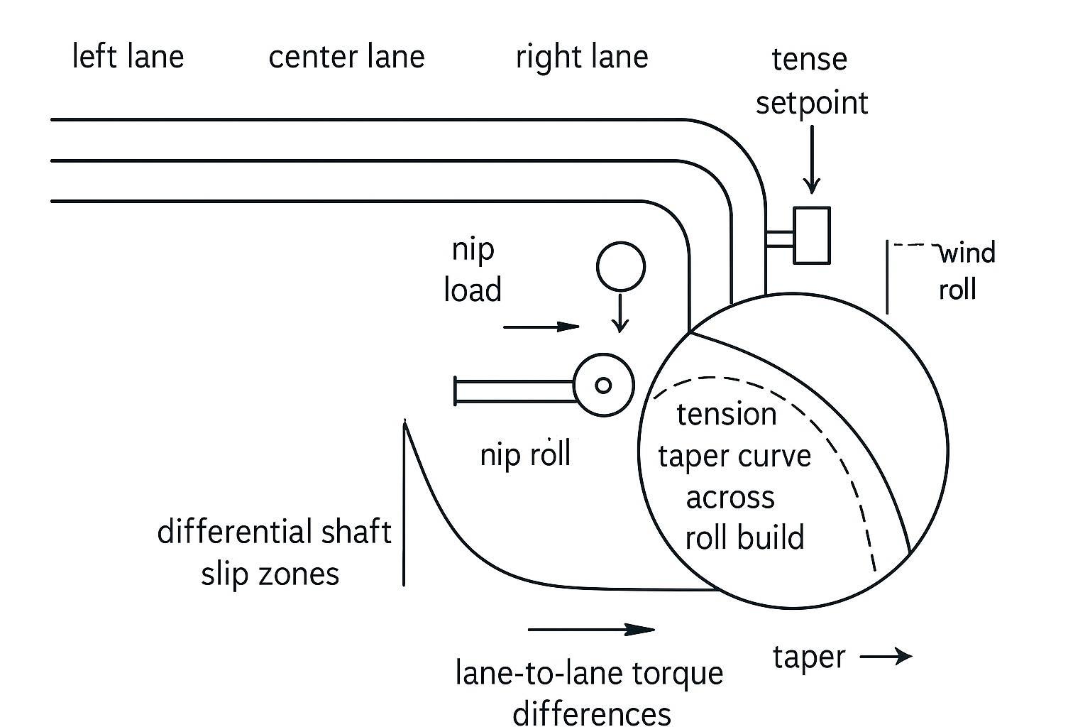
- Utilice la tensión cónica de forma intencionada; a medida que aumenta el diámetro, a menudo es necesario disminuir la tensión para evitar el efecto telescópico, el pandeo de los bordes o el aplastamiento de los núcleos.
Para un punto de partida basado en estándares sobre la guía de tensión de la banda, TAPPI publica documentos de guía de tensión como: TAPPI TIP 0200-01:2021 (directrices de tensión web).
Ejes diferenciales y mordazas
El bobinado diferencial suele ser la diferencia entre "carriles que se comportan correctamente" y "carriles que se desvían". Cuando los carriles aumentan su diámetro a ritmos ligeramente diferentes, el sistema necesita una forma controlada de igualar el par para que un carril no se afloje y comience a desviarse.
Comprobaciones:
- Confirme que los elementos del diferencial realmente patinan dentro del rango de par esperado.
- Verifique que la carga de presión esté equilibrada en toda la superficie del rodillo; una presión desigual puede crear diferencias de tracción entre los carriles.
- Revise la tensión de la conicidad junto con los ajustes diferenciales; si aumenta la tensión a medida que crece el diámetro, puede sobrecargar un carril y desestabilizar el seguimiento.
Transiciones y tracción
Muchos cortes de serpiente son “defectos de transición”:
- aceleración a la velocidad de producción
- pasaje de empalme
- transferencia de torreta
- La dureza del rodillo cambia a medida que aumenta el diámetro.
Durante las transiciones:
- Confirme que la tracción de la banda elástica sea uniforme (sin deslizamientos repentinos en un punto de la banda).
- Reduzca brevemente la velocidad como prueba diagnóstica. Si la deriva disminuye inmediatamente, sospeche de problemas relacionados con la dinámica del aire, la tracción o la estática antes de cambiar las cuchillas.
- Considere el desplazamiento irregular de la guía de borde como un síntoma, a menudo causado por oscilaciones de tensión, desalineación o tracción inestable.
Alineación y coincidencia de velocidad
Rodillos, ejes y equilibrio de presión
Si la geometría fuerza la telaraña lateralmente, ningún ajuste de la cuchilla la mantendrá recta de forma consistente.
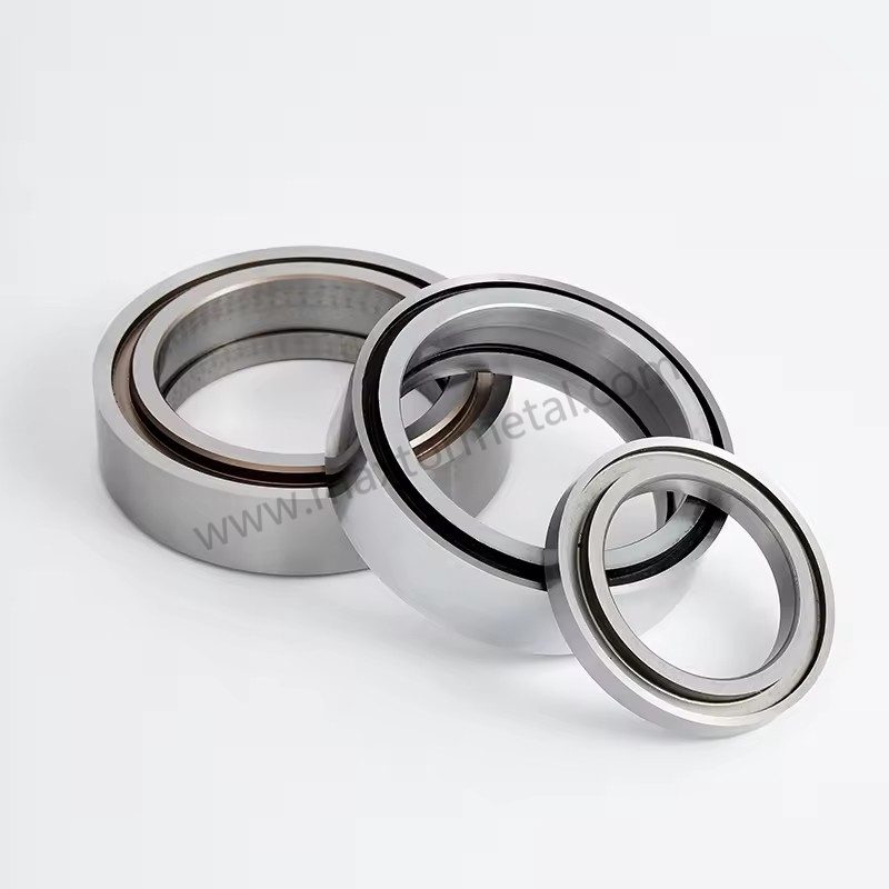
- Compruebe el paralelismo de los rodillos con respecto al eje central de la máquina.
- Inspeccione las caras de los rodillos para detectar conicidad, desgaste, contaminación o daños.
- Verifique la distribución de la presión de contacto; una presión desigual puede desviar la banda.
Una referencia práctica sobre los fundamentos del seguimiento de la línea central y las causas del movimiento lateral es la recopilación de Walker en la comunidad de manejo de web (ver Líneas web: Walker sobre el manejo de líneas web (compilación en PDF de 2003-2014)).
Diferencia de velocidad en el punto de cizallamiento
En el corte por cizallamiento, la diferencia de velocidad puede generar un componente de fuerza lateral en el punto de corte.
Lista de verificación:
- Verifique que la velocidad de la superficie de la cuchilla coincida con la de la banda donde lo requiera su método de corte.
- Confirme que el acoplamiento/juego del accionamiento no esté generando variaciones periódicas de velocidad.
- Si la deriva aumenta con la velocidad pero no con la tensión, sospeche de coincidencia de velocidad y vibración.
Salud y vibración de los rodamientos
Los problemas de rodamientos y vibraciones se disfrazan constantemente de "problemas de corte".
- Compare las temperaturas de los rodamientos izquierdo y derecho.
- Preste atención al ruido cíclico; compruebe si hay patrones.
- Si dispone de un sistema de monitorización de vibraciones, registre los espectros en el cabezal de corte y rebobine.
Efectos del material y del aire
Perfil y variabilidad del medidor
La variación del grosor transversal de la banda y la curvatura generan una tensión desigual entre los carriles. La banda generalmente se desplazará hacia el lado más tenso.
Comprobaciones:
- Verifique el perfil del rollo entrante y la consistencia de la dureza.
- Busque diferencias entre carriles que se correlacionen con la posición del eje principal (borde frente a centro).
- Si la desviación solo se produce en ciertos lotes, registre el ID del lote y los datos del perfil del medidor en su registro.
Arrastre de aire y acumulación
El aire es un verdadero “elemento mecánico” a altas velocidades. Si la tela se desliza sobre una capa de aire, la tracción cambia y el corte puede desviarse.
Comprobaciones:
- Presta atención a las fluctuaciones y a la mala alineación al rebobinar.
- Utilice la función de presión/aplastamiento de forma eficaz (dentro de los límites de la máquina) para reducir el aire atrapado.
- Como medida de diagnóstico, reduzca la velocidad ligeramente y observe si disminuye la inestabilidad del vehículo.
Vinculación de defectos estáticos y de borde
La carga estática puede atraer la película hacia las guías/rodillos, atraer polvo y desestabilizar los puntos de separación, especialmente en películas delgadas a velocidades elevadas.
Comprobaciones:
- Verifique la continuidad de la conexión a tierra en los puntos clave.
- Inspeccione las barras ionizadoras para comprobar su limpieza y rendimiento.
- Compruebe si el defecto empeora en condiciones de baja humedad.
When static-attracted dust is itself a product quality problem—not just a trigger for tracking instability—the blade-level root causes of dust generation (Ra, carbide microstructure, overlap-induced secondary rubbing) require a separate analysis. See Análisis de causa raíz de la generación de polvo de corte longitudinal: Ra del flanco de la cuchilla, microestructura del carburo y tolerancias de ajuste.
FAQs:
P: ¿Qué causa los cortes en serpentina en el corte de film?
R: Los cortes en serpentina suelen deberse a inestabilidad lateral: fuerzas en la cuchilla (desviación/runout, traslape, movimiento del portacuchillas), mecánica de la banda (desequilibrio de tensión, problemas de bobinado diferencial), geometría (desalineación, presión de rodillos despareja) o dinámica (atrapamiento de aire y electricidad estática). La vía más rápida para solucionarlo es aislar si la deriva comienza en la cuchilla o si se manifiesta durante el bobinado.
P: ¿Cómo saber si la desviación de la línea de corte es un problema de la cuchilla o de la tensión?
R: Si el problema ocurre solo en un carril específico y comienza justo en el corte, incluso a baja velocidad, sospeche de las cuchillas, la desviación (runout) o los portacuchillas. Si empeora a medida que aumenta el diámetro del rollo, mejora al cambiar la tensión o se desplaza con la posición del mandril, sospeche de la tensión o del bobinado diferencial.
P: ¿Puede la desviada o desalineación de la cuchilla (runout) causarle la deriva a las líneas de corte?
R: Sí. Incluso un pequeño descentramiento (runout) puede crear una fuerza lateral repetitiva que desvía la trayectoria del corte. Mida el descentramiento en el árbol/eje, las caras de los espaciadores y las caras de la cuchilla con un comparador de carátula (reloj comparador), y compare los carriles "buenos" con los "malos".
P: ¿Qué configuraciones de tensión ayudan a detener la deriva de la línea de corte en una cortadora rebobinadora?
R: Comience por estabilizar la tensión en cada zona y verificar la tensión real mediante mediciones. Luego, utilice un perfil de tensión cónica (taper) controlado para que la tensión no aumente a medida que se incrementa el diámetro. Las directrices publicadas por TAPPI pueden ayudarle a elegir el rango inicial, y posteriormente podrá ajustarlo según la dureza del rollo y la estabilidad de los carriles.
P: ¿Previenen los ejes diferenciales la deriva de los carriles y el telescopiado?
R: Ayudan cuando los diámetros de los carriles se incrementan de forma despareja, ya que el deslizamiento controlado iguala el par de apriete (torque) para que ningún carril quede destensado ni se desvíe. Si los elementos de fricción se atascan o el par se configura de forma incorrecta, aún pueden producirse diferencias de dureza entre carriles y desvíos laterales.
P: ¿Por qué empeora la desviación de la línea de corte a mayor velocidad?
R: Una mayor velocidad aumenta el atrapamiento de aire, magnifica la vibración y hace que las pequeñas desalineaciones tengan un mayor impacto. Si la deriva disminuye rápidamente al reducir la velocidad, sospeche de la dinámica del aire, la tracción o la electricidad estática antes de modificar la geometría de las cuchillas.
P: ¿Cómo puedo reducir el atrapamiento de aire al bobinar film?
R: Mejore la eficacia del rodillo de presión/contacto (lay-on/nip) dentro de los límites de la máquina, confirme la geometría de la trayectoria de la banda hacia el rebobinado y ajuste la tensión/conicidad (taper) para que la banda se adapte al rollo en lugar de desplazarse sobre una película de aire. Una prueba de reducción de velocidad es una forma rápida de confirmar si el aire es el causante de la inestabilidad.
P: ¿Dónde debo registrar los datos para evitar que los cortes en zigzag (snake cuts) vuelvan a ocurrir?
R: Registre por ID de rollo y carril: el ensamblaje del juego de cuchillas (diámetro exterior, grosor, espaciadores), lecturas de descentramiento (runout), ajustes de solape y ángulo de inclinación (cant angle), tensiones por zona y perfil cónico (taper), tipo y configuración del eje de rebobinado, velocidad, estado de mitigación de humedad/estática, y si la deriva cambió con la velocidad o el diámetro del rollo.
Conclusión
Eliminar los cortes en serpentina (snake cuts) requiere abandonar el ajuste empírico e impreciso y adoptar una rutina de diagnóstico sistemática basada en la física. Al verificar sistemáticamente la geometría de la cuchilla y la rigidez del portacuchillas (manteniendo un TIR ≤ 0.050 mm y el traslape/ángulo de inclinación adecuados), regularizar los perfiles de tensión de la banda en las zonas de bobinado y eliminar la desalineación de los rodillos de la máquina junto con el atrapamiento de aire a alta velocidad, las líneas de conversión de banda pueden lograr una estabilidad inmediata en la línea de corte.
Para transformar esta lista de comprobación en ganancias operativas duraderas, las plantas deben formalizar estas verificaciones en un procedimiento operativo estándar (SOP). La implementación de una hoja de configuración estandarizada —que incluya firmas obligatorias para el descentramiento (runout), el solape (overlap) y las lecturas de tensión— junto con el establecimiento de una cadencia de mantenimiento preventivo (PM) estricta para portacuchillas, ejes y rodamientos, reduce drásticamente la variabilidad en los cambios de formato.
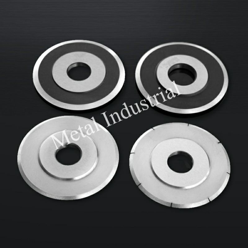
Para operaciones que estandarizan las herramientas en múltiples líneas de corte, Maxtor Metal suministra cuchillas circulares de corte con documentación completa de dimensiones y dureza por lote, y ofrece soporte OEM/ODM cuando las cuchillas deben coincidir con los planos existentes de árboles y portacuchillas. Cuchillos y cuchillas circulares de Maxtor Metal Para referencia geométrica y de especificaciones.
En última instancia, la medición del éxito de estos controles de estabilidad se reduce a indicadores clave de rendimiento (KPI). Las operaciones de conversión de alto rendimiento realizan un seguimiento de cinco KPI principales para validar su rendimiento de corte:
- Tasa de chatarra y desperdicio (%): Reducción directa de los residuos de película recortada y de los rollos rechazados que no cumplen con las especificaciones.
- Eficacia general del equipo (OEE): Mayor velocidad de carrera y estabilidad de corte sostenida.
- Tiempo de inactividad no planificado: Menos paradas de línea causadas por roturas de la banda o ajustes a mitad de la producción.
- Vida útil de la cuchillaMayor durabilidad de la herramienta gracias a la minimización de la carga lateral y a una superposición óptima.
- Quejas de los clientes sobre la calidad: Menor incidencia de defectos de tejido de bordes, telescopización o corte en los envíos de rollos terminados.
Autor/Revisor técnico
Jerry Chu Especialista en soporte técnico (servicio postventa)
Maxtor Metal
Jerry cuenta con más de 10 años de experiencia en aplicaciones multisectoriales en la fabricación de papel, el reciclaje y trituración de plásticos, el corte de metales y el procesamiento de madera. Especializado en la resolución de problemas reales de corte, como rebabas, exceso de polvo e inestabilidad de los bordes, trabaja directamente con los equipos de ingeniería de campo para optimizar el rendimiento de las herramientas y la fiabilidad operativa.
- CertificacionesProfesional Certificado en Mantenimiento y Confiabilidad (CMRP), Profesional en Gestión de Proyectos (PMP®)
- EspecialidadesSolución de problemas de corte in situ, diseño de geometría de cuchillas personalizadas y desarrollo de procedimientos operativos estándar (SOP) para mantenimiento preventivo.

 English
  Spanish
  Italian
  French
  Portuguese
  Russian
  German
  Arabic
  Hindi
Hindi  Vietnamese
  Indonesian
  Japanese
  Korean