

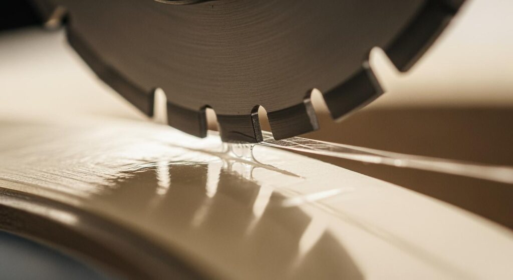
Lorsque l'adhésif commence à s'accumuler sur les lames de refend circulaires, le premier signe est rarement spectaculaire. Les bords de coupe deviennent légèrement collants. La géométrie de la bobine dérive. La qualité de découpe se dégrade avant même que le chef d'équipe ne puisse en déterminer la cause. Au moment où un dépôt polymère visible —une arête rapportée (BUE)— s'est formé sur la face de la lame, cela fait déjà plusieurs heures que la lame fonctionne à un rendement réduit.
Ce guide détaille les mécanismes d'accumulation d'adhésif sur les couteaux circulaires de refendage par cisaillement, les paramètres de réglage qui la freinent ou l'accélèrent, ainsi que les choix de matériaux et de maintenance qui distinguent les lignes de ruban à TRG (OEE) élevé de celles qui passent plus de temps en dépannage qu'en production. Les ingénieurs et responsables de production travaillant avec des rubans PSA, des films de protection et des bandes enduites d'adhésif y trouveront des plages de paramètres, des comparaisons de revêtements et une logique de diagnostic directement exploitables sur machine.
Pour circular knives and slitting blades used in adhesive-sensitive applications, understanding buildup physics is prerequisite to specifying the right tool and the right conditions.
Le guide pratique ci-dessous s'appuie sur plus de 15 années d'expérience pratique de Maxtor Metal dans la fabrication et le réaffûtage de couteaux de refendage circulaires de précision, ainsi que sur des données de terrain issues de lignes de rubans sensibles aux adhésifs et de films de protection. Lorsqu'un chiffre spécifique provient d'un essai client ou d'un test publié, la source est mentionnée afin que vous puissiez l'évaluer au regard de vos propres conditions.
Causes thermo-mécaniques
Heat–Contact Feedback Loop
The accumulation sequence begins at the shear point. As the upper circular blade and lower female ring engage the web, the adhesive layer — whether solvent-acrylic, hot-melt, or UV-cured PSA — is sheared and stretched at the cut face. At that moment, adhesive polymer chains with sufficient tack can bond to the blade surface.
The deposit begins small: microscopic polymer patches on the blade bevel. But buildup changes the effective cutting geometry, which increases drag, which generates more frictional heat. Heat reduces PSA cohesive strength and raises surface tack. That in turn accelerates transfer rate, reinforcing the cycle.
Points clés à retenir: Adhesive buildup is self-reinforcing. Once a polymer patch forms, local heat spikes raise tack and promote faster accumulation. Interrupting the loop early — through geometry, coating, or cleaning — is far less costly than recovering from a fully glazed blade.
This cycle is compounded at higher line speeds, where the blade’s heat dissipation rate cannot keep pace with frictional input, and at higher line tensions, which press the web harder against the knife edge.
Blade Condition and Geometry Effects
A sharp, correctly finished blade edge initiates a clean shear fracture through the adhesive layer. A worn or improperly finished edge drags rather than cuts — stretching adhesive strands across the blade face instead of severing them. Every worn micron of edge radius increases the contact zone and the likelihood of adhesive transfer.
Bevel geometry matters independently of sharpness. A double-hollow-ground bevel reduces the land area in contact with the cut face, lowering the surface available for adhesive to wet and bond. A conventional flat bevel keeps a larger land in continuous contact with the material — which is why double-hollow or compound-bevel grinds are often specified for high-tack PSA applications.
For a rigidity-led framework on choosing between single, double, and compound bevel geometries — including included-angle selection by substrate family and the trade-off between tip structural support and adhesive contact-land area — see Biseaux simples, doubles et composés pour couteaux à refendre circulaires.
Surface roughness is equally critical. An edge finish target of Ra ≤ 0.10 µm (mirror-level polish) significantly reduces adhesive anchor points compared to a standard-ground finish in the Ra 0.2–0.4 µm range. Rough surfaces provide micro-pockets where polymer chains can mechanically interlock, even when the adhesion thermodynamics would otherwise be marginal.
Adhesive Rheology and Environment
Not all PSA systems present equal risk. Rubber-based PSAs tend to be more cohesive, which helps them separate cleanly from the blade. Acrylic PSAs — particularly those formulated for aggressive peel strength — have lower cohesive strength relative to their tack, making them more prone to cohesive failure at the slit face and subsequent blade transfer. Hot-melt PSAs are temperature-sensitive: ambient shop floor temperature above 25 °C can meaningfully increase their deposition rate.
Humidity matters less for most PSA tapes than for hygroscopic paper stocks, but electrostatic charge — generated during unwinding and slitting — can attract fine adhesive particles to the blade face independently of the mechanical cutting process. Facilities running at relative humidity below 40% will encounter elevated static activity.
Paramètres de réglage contrôlant l'encrassement
Overlap, Cant Angle, Side Load
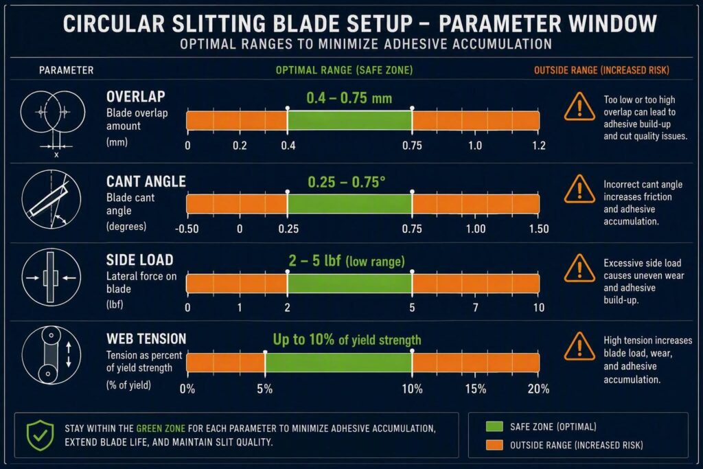
These three parameters define the cutting engagement geometry. All three affect heat generation and adhesive deposition rate, and all three have narrow optimal windows for PSA-sensitive applications.
Chevaucher is the vertical penetration of the upper blade past the tangent surface of the lower ring. Published shear-slitting references generally recommend starting at approximately 0.030 in. (0.76 mm) for most film and label materials, then adjusting from there. For PSA-coated webs, the practical starting window is 0.4–0.75 mm: enough to produce a full shear fracture without excess rubbing on the blade face. Over-overlap increases heat and contact time; under-overlap leaves adhesive strands uncut, which then string and deposit on the knife.
Cant angle — the angular tilt of the upper blade relative to the web — creates the progressive shear action that completes the cut. In established shear-slitting practice, the typical cant range for flexible laminates and tape constructions is 0.25°–0.75°, with 0.50° the most commonly used starting point. Higher angles increase edge contact and should only be used when the material fiber structure specifically requires it.
Side load is the lateral force holding the upper blade in contact with the lower ring. Typical pneumatic side-load values sit in the 2–7 lbf range and should not vary by more than about 0.5 lbf during a run. For adhesive-sensitive applications, target the lower end: 2–5 lbf. This minimizes rubbing friction at the blade-ring interface without sacrificing cutting stability.
The setup sequence matters: set cant angle first and lock it, then set overlap conservatively, then add the minimum side load that maintains stable contact.
For a DOE-based analysis of how overlap depth and side clearance interact across substrate families — with Pareto trade-off data between edge quality and knife life that covers adhesive-coated webs — see Optimisation de la profondeur de chevauchement et du jeu latéral des couteaux circulaires.
These three parameter windows — overlap 0.4–0.75 mm, cant angle 0.25°–0.75°, side load 2–5 lbf — represent the commissioning baseline Maxtor Metal’s application engineering team uses when qualifying circular shear-slitting knives for PSA tape and protective film lines. Staying within these windows from the first production run is the single most effective way to prevent the heat–contact feedback loop from establishing itself.
For a detailed treatment of how spring-loaded preload interacts with overlap and cant angle during shear slitting setup — and how to lock in stable contact geometry before adding coating and lubrication — see Dispositif à ressort pour le refendage par cisaillement à jeu nul : contrôle du chevauchement, de l’angle d’inclinaison et de la précharge.
Web Tension and Speed Stability
Web tension that varies cycle-to-cycle creates micro-fluctuations in blade engagement force, translating directly into adhesive transfer variation. In precision slitting, the usual target is to hold tension accuracy within 1% at constant speed. A general starting point for most PSA tape constructions is ≤10% of the web material’s tensile yield strength, calibrated downward for softer constructions.
Speed changes are an underappreciated variable. Acceleration and deceleration phases put the blade through a brief high-friction transient as the cutting geometry settles. If buildup is concentrated near reel starts or ends, line speed ramp control is the most probable cause.
Blade Temperature as a Leading Indicator
Blade surface temperature is the best real-time indicator of accumulation risk. A fixed-mount IR pyrometer aimed at the knife face gives process engineers a leading signal that precedes visible buildup by 10–30 minutes on most tape constructions. Establish a baseline temperature for a clean blade at production speed, and treat any sustained rise of 8–12 °C above that baseline as an early warning to inspect and clean.
Field Case: Label-Stock Line Cutting Cleaning Intervals by 75%
The following example draws on published converting industry field reports and aligns with results Maxtor Metal’s technical team has observed across label-converting and PSA tape projects. It is included to illustrate the magnitude of improvement achievable when geometry, surface finish, and coating are optimized together.
A representative example comes from the label-converting segment, where adhesive buildup is the dominant cause of unplanned blade changes. On a line slitting pressure-sensitive label stock, operators reported the classic symptoms: slit edges turning tacky within a few hours, dust and adhesive smearing on the blade face, and cleaning stops that kept getting shorter. Rather than replacing blades blindly, the documented solution path runs through geometry and surface treatment together: change the blade bevel geometry, switch to polished top blades finished to a 1–2 RMS (≈ 0.025–0.05 µm Ra) surface, add an oil wick or wiper, and apply a special low-energy coating to both top and bottom blades.
Field reports from this approach point to one of the few quantified figures available in the public domain: the special top-and-bottom blade coating reduced adhesive build-up by as much as 75%, and these blades commonly ran 7 to 8 hours between cleanings on label stock.
Translated to the shop floor, this is the difference between cleaning a blade every shift and cleaning it roughly once per shift with margin to spare. The measures map directly to the mechanisms in this guide — polished finish (fewer anchor points), wiper/wick (boundary lubrication), and coating (low surface energy) each attack a different link in the heat–contact–tack loop.
Choix des matériaux et des revêtements
Blade Substrates and Edge Finishes
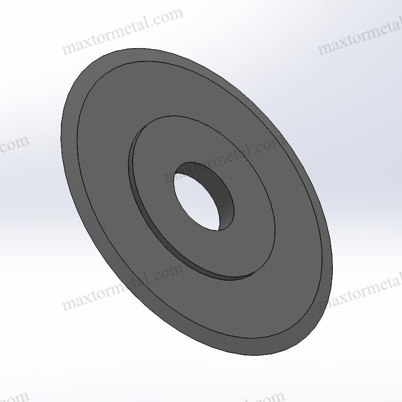
The substrate steel determines achievable hardness, the surface finish attainable after grinding, and the adhesion performance of any subsequent coating. High-speed steel (HSS) grades such as M2 (typically 62–64 HRC after heat treatment) support the Ra ≤ 0.10 µm finish targets required for PSA applications and provide adequate toughness for thin film slitting. High-chromium, high-carbon tool steels achieve similar hardness but require careful edge geometry management to avoid micro-chipping on flexible film constructions.
Solid carbide circular blades are generally over-engineered for soft PSA films and can suffer edge micro-chipping when the substrate lacks the compliance to absorb vibration loads. They are better matched to metallic foil or hard-film slitting.
Specify the edge finish in your blade procurement documents. Superfinishing to Ra ≤ 0.10 µm — achievable by lapping or fine-grit honing after grinding — measurably reduces adhesive deposition rate compared to a standard-ground edge in the Ra 0.2–0.4 µm range. Do not leave this to vendor default.
The role of blade flank Ra in controlling friction and particulate generation — including the carbide microstructure requirements for achieving and retaining a mirror finish — is covered in detail in Analyse des causes profondes de la génération de poussière de refendage : Ra du flanc de la lame, microstructure du carbure et tolérances de montage.
When you write the specification, anchor the verification to recognized standards rather than to a supplier’s word. Hardness is conventionally verified by the Rockwell method per ASTM E18 (or Vickers/micro-hardness for thin or coated edges), while dimensional and geometric tolerances are commonly controlled through ISO 2768-1 for general linear dimensions or ASME Y14.5 where GD&T is used. Naming the test method in the purchase order removes ambiguity about how compliance is demonstrated.
Low-Adhesion Coatings (DLC/TiN/CrN)
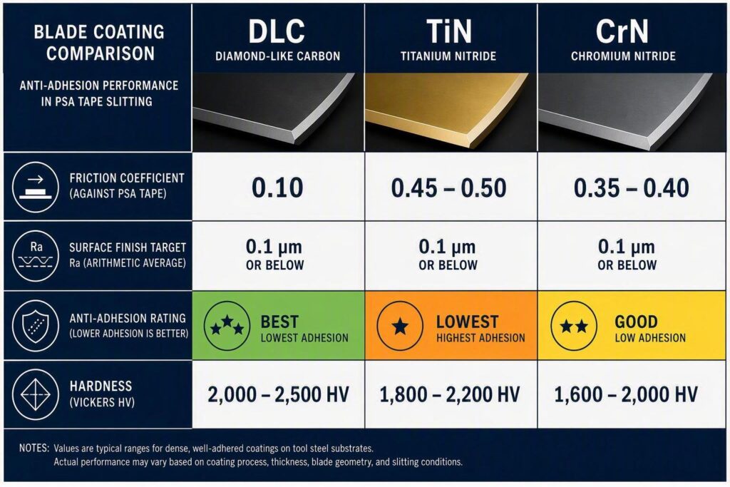
The three coatings most widely applied to circular slitting blades for PSA applications — DLC (diamond-like carbon), CrN (chromium nitride), and TiN (titanium nitride) — differ significantly in their tribological behavior against adhesives.
Published tribological data from Structure and Tribological Properties of TiN/DLC, CrN/DLC and Related Hybrid Coatings (Materials, 2025) reports friction coefficients (µ) at 10 N load of approximately 0.10 for DLC, 0.35–0.40 for CrN, et 0.45–0.50 for TiN. Lower friction at the blade-adhesive interface correlates directly with lower adhesive transfer rate.
The friction coefficients below are sourced from peer-reviewed tribological testing (Materials, 2025) and major coating supplier datasheets. These values inform Maxtor Metal’s coating recommendation sequence for PSA slitting applications.
| Revêtement | Friction coefficient (µ) | Anti-adhesion for PSA | Hardness (approx. HV) | Best fit |
|---|---|---|---|---|
| DLC | ~0.10 | Excellent | ≥ 1,500 | High-tack acrylic PSA, aggressive thin films |
| CrN | ~0.35–0.40 | Bien | ~1,800 | General PSA, label stock, rubber-based adhesives |
| Étain | ~0.45–0.50 | Modéré | ~2,300 | Wear resistance priority; not first choice for anti-stick |
DLC is the first choice where adhesive buildup is the dominant failure mode. Its ultra-low friction and chemical inertness prevent polymer chain bonding far more effectively than nitride coatings. CrN is a practical middle ground when DLC is not available or cost is constrained. TiN should not be selected primarily for PSA anti-adhesion performance, though it remains appropriate for harder, non-sticky substrate slitting where wear resistance is the priority.
The counterintuitive part: hardness does not predict anti-stick performance
There is a widespread procurement assumption that the harder the coating, the better it resists adhesive pickup. Published coating data does not support that assumption, and the reason is rooted in the buildup mechanism itself rather than in wear physics.
Consider the property sets from two major coating suppliers. Ionbond’s published coating specifications list dry friction against steel and microhardness in the following ranges: TiN around µ ≈ 0.5 at 2,500–3,100 HV, CrN around µ ≈ 0.5–0.55 at 2,100–3,000 HV, et certain DLC / metal-doped DLC (MeDLC) systems around µ ≈ 0.2 at a comparatively lower 1,000–1,800 HV. Oerlikon’s published BALINIT DLC data follows the same pattern from the opposite direction: a typical BALINIT DLC coating sits at roughly 15–25 GPa (≈ 1,500–2,500 HV) with a dry friction coefficient of 0.1–0.2 against steel, and Oerlikon explicitly attributes the coating’s benefit in plastics and adhesive-contact applications to its low friction and inert surface chemistry, which reduce adhesive wear, sticking, and deposit formation.
Read those two data sets together and the engineering conclusion writes itself: the hardest of the three coatings (TiN) has the highest friction, and the coating with the best anti-stick reputation (DLC) is not the hardest — it is the lowest-friction and most chemically inert. For a PSA slitting application, the failure mode is not abrasive wear of the blade; it is adhesive transfer, and adhesive transfer is governed by friction, surface energy, and heat — not by hardness.
This matters because hardness is the property most often written into a purchase specification and the easiest for a supplier to advertise. It is also the wrong control variable for this specific problem. Picking a coating on hardness alone is a reasonable strategy for cutting abrasive-filled or glass-fiber-reinforced substrates, where the dominant wear mechanism is abrasion. On a PSA tape line, it mis-targets the physics.
Coating selection for PSA slitting should not be based on hardness alone. Friction coefficient, surface chemistry, edge geometry, and thermal behavior must be evaluated together, because the buildup loop is thermal and chemical — heat softens the adhesive, softened adhesive transfers, transferred adhesive increases friction, and increased friction generates more heat. A coating that wins on hardness but loses on friction is feeding the loop, not interrupting it.
The practical implication for spec sheets: when comparing coatings for an adhesive-sensitive line, ask the supplier for friction coefficient and surface energy data alongside hardness, and evaluate them in that order of priority. If a supplier can only quote hardness, the data set is incomplete for this application.
Coating adhesion to the substrate is as important as coating chemistry. PVD (physical vapor deposition) processes produce dense, well-bonded films. Verify with your blade supplier that coating thickness is uniform across the blade face — edge coverage failures are a common cause of early delamination in slitting service.
For a deeper comparison of DLC and PTFE coating behavior across wear-limited and transfer-limited failure modes — including how each coating ages under repeated cleaning cycles — see Guide de Sélection des Revêtements DLC vs PTFE pour Lames de Refendage : Usure vs Transfert de Matière.
Geometry Matching to PSA and Substrates
Coating and substrate choices work in combination with edge geometry, not as a substitute for it. A DLC-coated blade run with an over-overlap setup will still accumulate adhesive faster than an optimally configured uncoated blade. The sequence is always: correct geometry first, then surface treatment.
For thin PSA films (< 60 µm total construction), a compound bevel or double-hollow grind reduces the contact land to the minimum needed for structural integrity. For thicker, stiffer constructions — foam tapes, heavy-gauge protective film — a standard bevel with appropriate side clearance provides the rigidity needed to prevent chatter.
Maintenance et contrôle de l'électricité statique
Cleaning Intervals and Approved Solvents
Cleaning intervals should be set by processed-meter count per SKU, not by calendar time. For aggressive acrylic PSA applications, intervals as short as 2,000–3,000 m are common; for light label stock or rubber-based PSA, 5,000–10,000 m intervals are often workable.
Solvent selection requires chemical compatibility checking against both the PSA adhesive type and the blade coating. Isopropyl alcohol (IPA) is the most widely compatible starting choice for acrylic PSA residue on DLC and CrN coated blades. Methyl ethyl ketone (MEK) is more aggressive and effective against hot-melt residue but requires ventilation controls and compatibility verification with DLC coatings — some DLC chemistries can be affected by ketone solvents over repeated exposure. Avoid chlorinated solvents unless explicitly validated by the coating supplier. Ultrasonic cleaning in an appropriate solution is effective for off-machine blade cleaning without direct edge contact.
Always wipe in the direction away from the cutting edge. Wiping toward the edge can roll adhesive debris into the bevel and introduce abrasive particles that score the polished face.
Static Neutralization and Upstream Hygiene
Static charge on the web amplifies adhesive particle transfer to the blade face independently of cutting dynamics. On film slitting lines running at 150 m/min or above, triboelectric charge generated during unwinding can reach several kilovolts. Active ionizer bars mounted at the web entry point — upstream of the slitting station — suppress this charge before it reaches the cutting nip.
Upstream hygiene is equally important. Adhesive squeeze-out at web edges, overspray from coating stations, and contaminated idler rolls all contribute to blade contamination on many lines. Audit the full material path from unwind to slitting station as part of any systematic contamination reduction program. A clean web entering the slitting station is worth more than any blade coating.
Lubrication and Anti-Stick Aids
Controlled blade lubrication is among the most effective interventions for adhesive-sensitive applications. The two most common delivery methods are:
- Felt wick systems: Lubricated felt pads mounted in the blade holder contact the rotating blade face continuously. Saturation with silicone oil or a purpose-formulated non-transfer lubricant keeps the face conditioned throughout the run.
- Oil-mist systems: A fine silicone oil mist applied to the blade face creates a thin boundary layer that prevents adhesive bonding without adding visible contamination to the slit edge.
Check lubricant compatibility with the downstream use of the slit material. Silicone contamination is problematic for automotive tapes and some medical constructions where adhesion to painted or primed surfaces is required.
Dépannage et traçabilité du contrôle qualité (CQ)
Symptom-to-Action Diagnostic Logic
| Symptôme | Most likely cause | First action |
|---|---|---|
| Tacky slit edge | BUE on blade face | Stop, clean blade; check overlap and blade temperature |
| Edge quality degrading mid-reel | Heat buildup | Check IR temperature baseline; reduce line speed 5–10%; inspect edge |
| Visible polymer deposit on bevel | Accumulated PSA transfer | Clean with approved solvent; inspect edge for wear; verify cant angle |
| Adhesive stringing across slit | Under-overlap or worn edge | Increase overlap in 0.1 mm increments; check edge sharpness |
| Buildup concentrated at reel start | Acceleration phase heat surge | Reduce speed ramp rate; inspect tension control at startup |
| Buildup concentrated at reel end | Reduced tension at unwind core | Taper tension profile; calibrate dancer / load cell |
| Sudden increase in cleaning frequency | Upstream contamination or coating delamination | Audit material path for squeeze-out; inspect blade coating integrity |
Conseil de pro: Keep a per-SKU blade temperature log. When a specific tape construction shows temperature excursions above its clean-blade baseline, it often signals an incoming batch with elevated adhesive tack or a process drift — identifiable before the first off-spec roll ships.
Layered Diagnostic Decision Logic
The table above maps a single symptom to a first action — useful for firefighting. But most recurring buildup problems are not a single fault; they are a chain, and the fastest way to a durable fix is to walk the chain in a deliberate order. The sequence below is the diagnostic logic Maxtor Metal’s application engineering team applies to adhesive-sensitive slitting problems: identify the symptom, test the condition, act, and — critically — if the action does not resolve it, move to the next branch rather than repeating the same first action.
Step 1 — Confirm the deposit is actually adhesive, not wear debris. Before adjusting anything, establish what is on the blade. A transparent, tacky film that wipes off with solvent is adhesive transfer. A dark, hard, adherent layer is more likely coating wear or oxidized residue and points to a completely different corrective path. Cleaning and checking the wipe residue takes two minutes and prevents a whole class of misdiagnosis.
- If it wipes off and is tacky → continue to Step 2.
- If it is dark, hard, and resists solvent → stop tuning geometry; inspect the coating for delamination and verify substrate heat treatment.
Step 2 — Is buildup uniform along the run, or concentrated at reel start/end? The spatial pattern points to the mechanism.
- Concentrated at reel start → acceleration-phase heat surge. Reduce the speed ramp rate and inspect tension control at startup.
- Concentrated at reel end → tension decay at the unwind core as the roll diameter shrinks. Taper the tension profile and calibrate the dancer/load cell.
- Uniform across the run → a steady-state problem (geometry, coating, or material), not a transient. Continue to Step 3.
Step 3 — Walk the parameter window before touching the blade. A uniform steady-state buildup is almost always a parameter issue until proven otherwise, and parameters are cheaper to change than blades.
- Vérifier overlap first: is it inside 0.4–0.75 mm for this construction? Over-overlap adds heat and contact time; under-overlap strings adhesive onto the knife.
- Then check cant angle: is it inside 0.25°–0.75°?
- Then check side load: is it in the 2–5 lbf window and stable to ±0.5 lbf?
- If any parameter is out of window → correct it, run a 300–450 m verification pass, and re-measure. Do not change two parameters at once — you will not know which one fixed it.
- If all parameters are in window → continue to Step 4.
Step 4 — Check temperature behavior against baseline. With parameters ruled out, temperature tells you whether the problem is thermal or material. Compare the current blade temperature against the clean-blade baseline for that SKU.
- Temperature rising but material unchanged → suspect blade degradation (edge wear, coating loss). Measure the edge radius and inspect the coating under magnification.
- Temperature stable but adhesion still occurring → suspect the incoming material: adhesive tack, coat weight, or cure variation between batches. Quarantine the suspect lot and compare its certificate with the previously good lot.
- Temperature spiking intermittently → suspect mechanical: chatter, vibration, or a misaligned anvil. Check runout and contact pattern.
For a measurement-first approach to diagnosing axial and radial TIR — including cold-to-hot drift protocols and the defect signatures each runout mode produces on adhesive-sensitive film lines — see Axial Runout, Dynamic TIR, and Slit Edge Quality.
When runout or chatter is confirmed as a contributing factor, see Éliminer les coupures en serpentin lors du découpage de films : une liste de contrôle des systèmes for a full bearing, alignment, and tension diagnosis sequence.
Step 5 — Escalate to a controlled comparison only after Steps 1–4. If the problem persists with confirmed-clean material, in-window parameters, and stable temperature, you have reached the point where a blade-to-blade comparison is justified. Use the gravimetric test protocol in the next section to compare the current blade against an alternative (coating, finish, or geometry) under otherwise identical conditions. This is the last step, not the first, because it is the most time-consuming — and because Steps 1–4 eliminate the most common causes before you commit test time.
The value of the layered sequence is that it prevents the most expensive diagnostic error in slitting: changing the blade when the problem was a parameter, or changing parameters when the problem was a material batch. Walking the chain in order costs almost nothing and resolves the majority of buildup complaints before anyone touches a knife.
A Measurable Test Protocol for Adhesive Accumulation
Most buildup debates stay subjective — “the blade looks gluey.” A published patent test method offers a repeatable way to turn that into data. In U.S. Patent 6,423,392 / EP 1 159 368, PSA label constructions were slit with 3 pairs of stainless-steel blades and anvils at a nominal 0.5° blade-to-anvil cant angle et 0.0625 in. overlap, at a constant web speed of 400 ft/min (≈ 122 m/min) and constant side load. After each 2,500 ft (≈ 762 m) roll, the adhesive residue on the blades and anvils was removed and weighed — a gravimetric method that quantifies build-up directly instead of rating it low/medium/high (US 6,423,392).
You can adapt this into a qualification sequence that fits a normal production run. At each checkpoint, capture a small, consistent data set:
| Distance run (equivalent) | Enregistrer |
|---|---|
| 0 m (baseline) | Blade-face photo; blade temperature; motor current / cutting-load proxy |
| 150 m | Same set + adhesive transfer area estimate |
| 300 m | Same set |
| 450 m | Same set |
| 600 m | Same set |
| 750 m | Same set; weigh scraped residue (gravimetric); note time to next required cleaning |
Running this sequence once per blade type — uncoated vs. DLC vs. CrN, or standard finish vs. mirror finish — gives you a curve rather than a single data point, and turns “which blade lasts longer” into a defensible comparison. It also separates blade-origin problems from setup-origin problems, which is the core diagnostic question in the next section.
Recording Parameters and Blade Lot Data
Consistent QC traceability is the foundation for distinguishing blade-origin problems from setup-origin problems. Each blade should be documented at receipt with the material grade, heat treatment batch, surface finish measurement (Ra), and coating lot. On multi-knife setups, coating thickness batch-to-batch consistency also feeds into spacer stack-up error — small per-knife dimensional variation accumulates into axial shift that alters the calibrated shear clearance. For the stack-up math governing this, see Contrôle de la tolérance d'épaisseur cumulée dans le refendage multi-lames.
When blade performance deviates — through accelerated buildup, edge chipping, or dimensional drift — lot data makes it possible to determine whether the issue is systemic across a production batch or isolated to a specific machine setup.
Material verification through the blade supply chain is one area where traceability has direct operational value. An EN 10204 3.1 material test certificate (MTC) is a lot-specific inspection document: it reports the actual measured chemical and mechanical results for the specific heat or batch supplied, and is signed by an inspection representative organizationally independent of production. That is what distinguishes it from a generic 2.1 declaration — the numbers belong to the material you received, not to a catalog.
Maxtor Metal supplies full MTCs per EN 10204 3.1 with blade lots, covering chemical composition, hardness, and dimensional tolerances. This supports cross-referencing incoming blade quality against line performance data — a useful control for facilities managing adhesive-sensitive runs where blade-to-blade consistency directly affects OEE metrics. Buyers who need external, third-party validation of those results should note that EN 10204 3.2 adds precisely that independent verification layer; specify 3.2 when supply-chain risk or regulatory exposure warrants it.
OEE/TCO Impact and SLA Considerations
Adhesive accumulation affects OEE through three channels: unplanned stoppages for blade cleaning, scheduled preventive cleaning events that consume available production time, and quality losses from off-spec slit edges. A line running 10-minute cleaning events every 2,500 m at 200 m/min loses approximately 0.8% of available production time per cleaning cycle — before accounting for inspection and re-qualification time.
TCO calculations for blade selection should account for:
- Coating premium vs. cleaning labor: A DLC-coated blade may cost 2–3× a standard blade but can reduce cleaning frequency by 40–60% on aggressive PSA applications, shifting TCO decisively in its favor across a 12-month operating window.
- SLA and reject rate: A single adhesive-contaminated roll per shift creates disproportionate rework costs on pressure-sensitive and optical film constructions, where adhesive defects are often detectable only at the customer’s laminating or die-cutting step.
- Regrind intervals: Frequent cleaning without adequate solvent-coating compatibility control can accelerate coating degradation, forcing earlier regrind cycles. Documenting the relationship between cleaning frequency, solvent type, and coating life is the basis for accurate regrind cost modelling.
- Bore fit and arbor precision: A blade that meets all coating and finish specifications but sits on an under-toleranced bore will generate intermittent contact-pressure variation — which drives adhesive transfer in the same way excess overlap does, but is invisible to setup parameter audits. For the ISO 286 fit selection logic that controls assembled TIR at the arbor level, see Tolérance d'alésage central et faux-rond : optimisation des ajustements ISO 286 pour les lames de refendage à grande vitesse.
FAQ
Q : Pourquoi de l'adhésif s'accumule-t-il sur les couteaux de refendage circulaires ?
R : Le transfert d'adhésif commence au point de cisaillement où la lame entre en contact avec la couche de PSA. La chaleur de frottement à l'interface lame-bande ramollit l'adhésif, diminue sa résistance cohésive et favorise son transfert sur la face de la lame. Dès qu'un dépôt de polymère se forme, il modifie la géométrie de coupe, augmente la résistance au frottement et accélère la production de chaleur — un cercle vicieux auto-entretenu. La combinaison d'une rugosité de surface de lame supérieure à Ra 0,10 µm, de paramètres de réglage sous-optimaux (chevauchement excessif, charge latérale trop importante) et d'une chimie d'adhésif à haute tack (adhésivité initiale élevée) provoque les accumulations les plus sévères.
Q : Quels réglages de chevauchement et d'angle d'inclinaison réduisent l'encrassement par l'adhésif ?
R : Pour la plupart des applications de rubans PSA et de films de protection, commencez avec un chevauchement (overlap) de 0,4 à 0,75 mm et un angle d'inclinaison (cant angle) de 0,25° à 0,75°, 0,50° étant le point de départ le plus courant pour les structures flexibles. Utilisez toujours les valeurs de paramètres minimales permettant d'obtenir une coupe nette — un chevauchement excessif augmente le temps de contact avec la face du couteau et la chaleur dégagée. Une charge latérale de 2 à 5 lbf (partie basse de la plage habituelle) réduit le frottement à l'interface couteau-contre-couteau sans compromettre la stabilité de coupe.
Q : Quel revêtement de lame est le meilleur pour la découpe de ruban PSA ?
R : Le DLC (carbone type diamant) offre le coefficient de frottement le plus bas (µ ≈ 0,10) et la plus forte résistance à l'adhésion parmi les trois options courantes. Le CrN (µ ≈ 0,35–0,40) constitue une alternative pratique lorsque le DLC n'est pas disponible ou en cas de contraintes budgétaires. Le TiN (µ ≈ 0,45–0,50) offre une dureté supérieure mais des performances anti-adhésives plus faibles, ce qui en fait un choix secondaire pour les applications de rubans PSA.
Q : À quelle fréquence les couteaux de refendage doivent-ils être nettoyés lors de la découpe de ruban adhésif ?
R : Définissez la fréquence de nettoyage en fonction du métrage traité par SKU, et non par durée calendaire. Pour un PSA acrylique à haute adhésivité (high-tack), un intervalle de 2 000 à 3 000 m entre chaque nettoyage est typique. Pour des supports d'étiquettes plus légers ou un PSA à base de caoutchouc, on atteint souvent 5 000 à 10 000 m. La surveillance de la température de la face de la lame à l'aide d'un pyromètre infrarouge fixe fournit un signal d'alerte précoce : une hausse soutenue de 8 à 12 °C par rapport à la température de base d'une lame propre indique qu'il est temps d'inspecter et de nettoyer avant qu'un dépôt visible ne se forme.
Q : Quels solvants sont sûrs pour éliminer les résidus de PSA sur les couteaux de refendage revêtus ?
R : L'alcool isopropylique (IPA) est le solvant le plus largement compatible pour les résidus de PSA acrylique sur les couteaux revêtus DLC et CrN. La méthyléthylcétone (MEK) est plus agressive et efficace contre les résidus de PSA thermofusible (hot-melt), mais elle nécessite un contrôle de la ventilation et une vérification de la compatibilité avec la chimie spécifique du revêtement. Évitez les solvants chlorés à moins que le fournisseur du revêtement ne les ait explicitement validés. Essuyez toujours en s'éloignant du tranchant pour éviter d'incruster des débris dans le biseau.
Q : Comment la charge statique contribue-t-elle à la contamination des lames lors du refendage de ruban adhésif ?
R : La charge triboélectrique générée lors du déroulement de la bande et du contact avec les rouleaux de renvoi peut atteindre des niveaux de kilovolts sur les lignes de refendage de films à des vitesses de production. Ce potentiel électrostatique attire les fines particules d'adhésif et la poussière vers la face de la lame, indépendamment du processus de coupe mécanique. Des barres ionisantes actives montées en amont du point de pinçage du refendage constituent la solution de contrôle standard. Maintenir l'humidité relative de l'atelier entre 40 % et 60 % réduit également la génération d'électricité statique le long du trajet de la bande.
Q : Quel est l'argument du TCO (coût total de possession) en faveur des couteaux revêtus de DLC par rapport aux couteaux non revêtus dans le refendage de PSA ?
R : Les revêtements DLC présentent un surcoût de 2 à 3 fois par rapport aux lames non revêtues ou revêtues de TiN. Dans les applications PSA, le DLC permet de réduire la fréquence de nettoyage de 40 à 60 %, réduisant ainsi la main-d'œuvre, la consommation de solvants et les pertes de TRG (OEE) liées aux micro-arrêts. Sur une ligne réalisant un nettoyage de 10 minutes tous les 2 500 m, une baisse de 50 % de la fréquence se traduit par environ 0,4 % de temps de fonctionnement supplémentaire par jour. La prévention des rejets clients dus à un seul rouleau contaminé renforce encore le TCO du tooling revêtu.
Q : Comment savoir si un problème d'accumulation d'adhésif provient de la lame ou du réglage de la machine ?
R : Commencez par la traçabilité du lot de lames : vérifiez le certificat d'essai des matériaux pour la nuance du substrat, la dureté et l'état de surface. Si la lame est conforme aux spécifications, auditez les paramètres de réglage — chevauchement, angle d'inclinaison, charge latérale et tension de la bande — par rapport à la plage documentée pour cette référence (SKU). Si les réglages sont corrects, inspectez le lot de matière première entrante à la recherche de variations de collance (tack) de l'adhésif, de grammage de couchage et de constance de réticulation. L'enregistrement de la température de la lame par SKU fournit le signal de diagnostic le plus net : si la température a augmenté par rapport à la référence sans modification des réglages, soit la lame s'est dégradée, soit les caractéristiques de la matière première entrante ont évolué.
Conclusion
L'accumulation d'adhésif sur les couteaux de refendage circulaires est stimulée par une boucle de rétroaction chaleur-contact-adhésivité qui, une fois amorcée, s'accélère. Les leviers à la disposition des équipes de production agissent sur trois niveaux : la mécanique (chevauchement, angle d'inclinaison, charge latérale, tension de la bande), les matériaux (substrat, état de surface du tranchant, choix du revêtement) et la maintenance (fréquence de nettoyage, solvant, lubrification, contrôle statique).
Les plages de paramètres — chevauchement 0,4 à 0,75 mm, angle d'inclinaison 0,25° à 0,75°, charge latérale 2 à 5 lbf, tension de la bande maintenue stable à ≤10 % de la limite d'élasticité — représentent la plage de fonctionnement pratique pour la plupart des structures de rubans PSA et de films de protection. Dans cette plage, un revêtement DLC ou CrN sur un substrat poli miroir (Ra ≤ 0,10 µm), soutenu par une lubrification programmée par mèche en feutre et un nettoyage périodique, offre le taux de dépôt d'adhésif total le plus bas réalisable avec l'outillage actuel.
Pour une mise en œuvre progressive, commencez par documenter la température de référence de la lame et l'intervalle de nettoyage par SKU. Ces données permettent d'identifier les applications générant une charge de maintenance disproportionnée et de justifier des améliorations ciblées de revêtement. Ajoutez la traçabilité des MTC por lot à la réception des lames pour fermer la boucle de rétroaction entre la qualité de l'outillage entrant et le rendement de la ligne.
When selecting or qualifying circular knives for adhesive-sensitive slitting applications, align the specification — steel grade, heat treatment, surface finish, and coating — to the adhesive chemistry and construction thickness of the primary SKUs you run. A correctly specified blade, properly maintained and documented, will outperform the best troubleshooting protocol applied to an incorrectly specified one.
Références et lectures complémentaires
The guidance in this article draws on the following standards, peer-reviewed research, and patent literature. Each is included so readers can verify the underlying figures and apply the methods to their own operations.
Standards and certification
- ASTM E18 — Standard Test Methods for Rockwell Hardness of Metallic Materials. The reference test method for verifying blade substrate hardness. Official ASTM page; full text is available for purchase.
- ASTM D1894 — Standard Test Method for Static and Kinetic Coefficients of Friction of Plastic Film and Sheeting. Establishes the friction measurement basis for film and tape surfaces. Official ASTM page; full text is available for purchase.
- ISO 2768-1 — General tolerances, Part 1: Tolerances for linear and angular dimensions without individual tolerance indications. Commonly used for general blade dimensional control. Official ISO catalogue page; full text is available for purchase.
- ASME Y14.5 — Dimensioning and Tolerancing. Applied where blade drawings use GD&T. Official ASME page; full text is available for purchase.
- EN 10204 — Metallic products — Types of inspection documents. Defines the 2.1, 2.2, 3.1, and 3.2 certificate types; Type 3.1 reports batch-specific test results signed by an inspection representative independent of production. Official BSI page for BS EN 10204:2004 (the official English-language version of EN 10204:2004, issued by CEN).
Peer-reviewed research
- Matériaux (MDPI, 2025) — “Structure and Tribological Properties of TiN/DLC, CrN/DLC and Related Hybrid Coatings” — friction coefficients for DLC, CrN, and TiN coatings.
- Chemical Engineering & Technology (Wiley, 2023) — “Tribological Performances of Diamond-Like Carbon Coatings” — hardness and friction values for commercial DLC coating systems.
Coating supplier technical data (for friction vs. hardness comparison)
- Ionbond — Tribobond 42 (DLC) coating data: microhardness 2,000–2,800 HV, friction vs. steel < 0.1. Manufacturer-published coating specification.
- Ionbond — Ionbond 01 (TiN-based) coating data: friction vs. steel (dry) ≈ 0.55. Manufacturer-published coating specification.
- Oerlikon Balzers — Carbon-based BALINIT DLC coating series: coating hardness ≈ 15–25 GPa and coefficient of friction 0.1–0.2 (dry, against steel), with low-friction, inert surface chemistry reducing adhesive wear, sticking, and deposits. Official Oerlikon product literature.
Patent literature
- U.S. Patent 6,423,392 / EP 1 159 368 — «Pressure-sensitive adhesive compositions and pressure-sensitive adhesive label constructions exhibiting low adhesive residue in printers« — describes the slitting test and gravimetric residue-weighing method referenced in the measurement protocol.
À propos de l'auteur
Jerry Chu — Technical Support Specialist, After-sales Service, Maxtor Metal
Jerry Chu is a technical support specialist with 10 years of hands-on experience in industrial cutting applications, spanning papermaking, plastics granulation, metal slitting, and wood processing. He works directly on customer sites to resolve practical cutting problems — edge burrs, excessive dust, adhesive build-up, and premature blade wear — and translates those field observations into blade specifications that hold up in production. He holds the PMP (Project Management Professional) and CMRP (Certified Maintenance & Reliability Professional) credentials.
The field guidance in this article reflects the practical troubleshooting perspective Jerry brings to adhesive-sensitive slitting applications, where a correctly specified blade and a disciplined maintenance routine consistently outperform reactive problem-solving.

 English
  Spanish
  Italian
  French
  Portuguese
  Russian
  German
  Arabic
  Hindi
Hindi  Vietnamese
  Indonesian
  Japanese
  Korean