

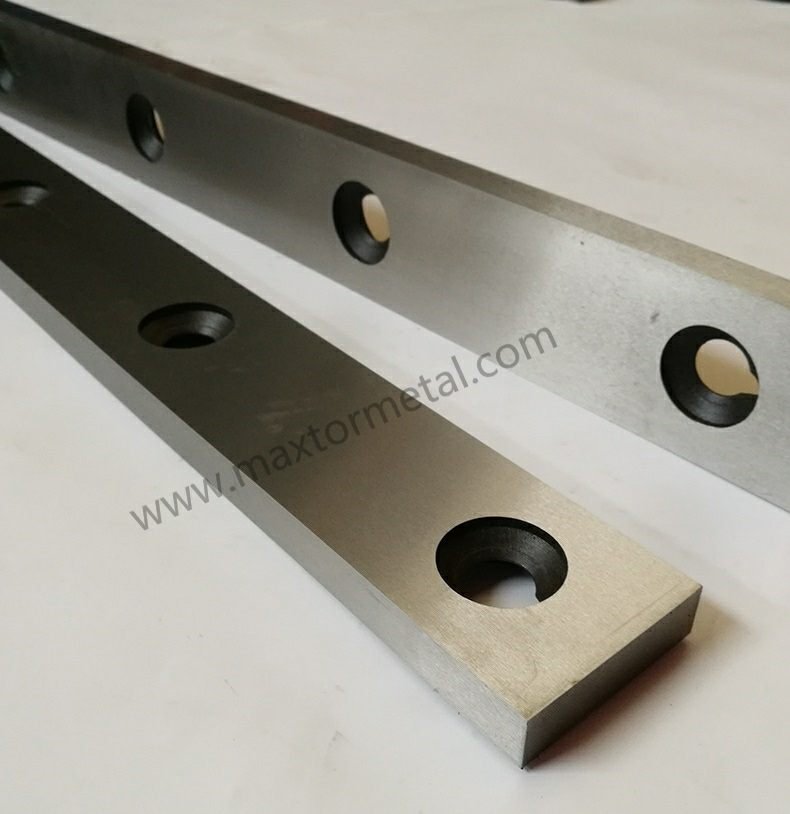
Si vous utilisez une cisaille guillotine sur un mélange d'acier au carbone, d'acier inoxydable et de nuances à haute résistance, vous connaissez déjà le schéma de défaillance : les bavures augmentent, les opérateurs « courent » après le réglage du jeu et les temps d'arrêt deviennent réactifs.
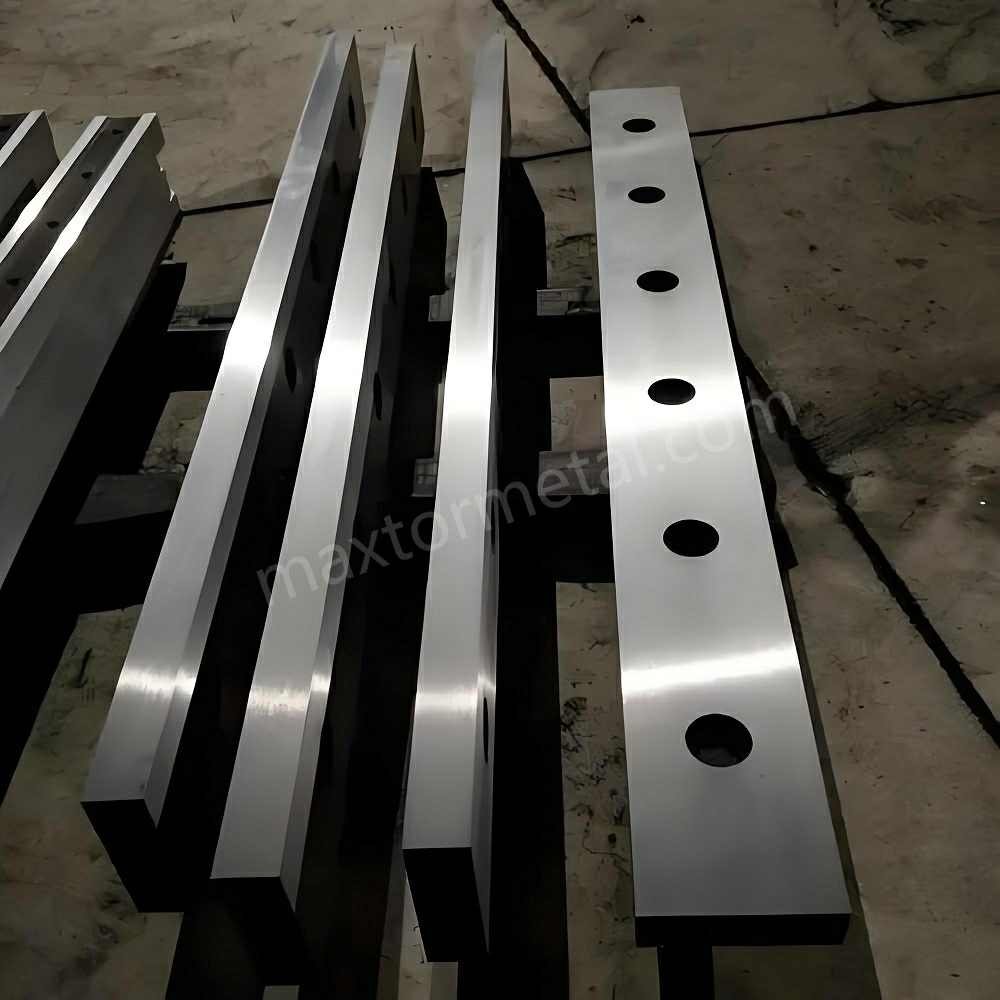
Cet article définit un protocole basé sur des mesures pour les lames réversibles à 4 côtés : quand effectuer la rotation, quand réaffûter et quelles données enregistrer pour que le processus soit prêt pour les audits tiers. À titre de contexte uniquement (et non comme argument commercial), cette catégorie est visible sur la page produit des lames de cisailles Maxtor Metal..
- Objective: define a data-driven 4-edge reversible blade rotation schedule and regrind criteria.
- KPIs: burr height, clearance accuracy, edge geometry, OEE/TCO impact, safety.
- Scope: 0.5–20 mm carbon, stainless, and high-strength steels; third-party audit ready.
Note d'ingénierie : Chez Maxtor Metal, les lames de cisailles guillotines fournies pour la coupe de matériaux mixtes sont documentées avec des données de rectitude et d'épaisseur mesurées en usine, ce qui permet de lier la ligne de base du jeu à la géométrie réelle de la lame plutôt qu'aux spécifications nominales. Voir l'aperçu technique des lames de cisaille Maxtor Metal]
Fondamentaux du réglage du jeu
Baseline and material factors
A consistent guillotine shear blade clearance setup starts with a baseline and a disciplined way to adjust it as material strength changes.
A widely adopted baseline for guillotine shear clearance is ~7% of material thickness, with two directional failure modes that define the usable window:
- Too much clearance → tearing and burr.
- Too little clearance → a double cut/step.
Important: Treat ~7% comme un starting reference, not a universal specification. The valid clearance window depends on the machine, blade condition, and the material’s strength and thickness—and must be verified on your specific shear by measuring left/center/right and confirming with controlled test cuts.
Where available, record and follow your OEM’s stated blade-gap guidance. For example, the Tennsmith LM/MSE manual notes a factory-set blade clearance of .003 in at the ends and .002 in at the center, and emphasizes that clearance must be reset after turning to a new edge or after re-sharpening (Tennsmith MSE1016 Operation & Maintenance Manual; see References section).
Setting and verifying the gap
Treat clearance as a measured setting, not a knob position.
Minimum tool kit
- Feeler gauges (clean, undamaged)
- Micrometer/caliper (material thickness + blade checks)
- Dial indicator (parallelism checks)
- Clean shims (if your shear uses shim packs)
Verification sequence (repeatable, audit-friendly)
- Isolate/lock off the machine and confirm guards/hold-downs are safe.
- Clean blade seats and clamping faces (chips under a seat behave like “bad clearance”).
- Measure actual sheet thickness (don’t trust nominal).
- Set target clearance and record the basis (thickness + material class).
- Verify clearance at left/center/right with a feeler gauge.
- Run a short test cut on representative scrap and inspect the edge.
Points clés à retenir: If left/center/right don’t agree, your “clearance” is three different clearances.
For a step-by-step calibration checklist (parallelism first, then clearance), Maxtor Metal’s guillotine blade setup guide on calibrating parallelism and clearance is a useful reference.
Compensating after regrind
Regrinding changes installed geometry and seating height. Your protocol should treat “post-regrind install” as a controlled setup event:
- Clean seats, verify torque, then re-check clearance at left/center/right.
- Record the measured values as the new baseline.
- Confirm with a test cut before releasing to production.
The burr-height bands in the tables below reflect the measurement criteria Maxtor Metal uses when evaluating blade condition during field audits for shear blade customers.
Seuils de bavure et géométrie du tranchant
Burr height bands by thickness and strength
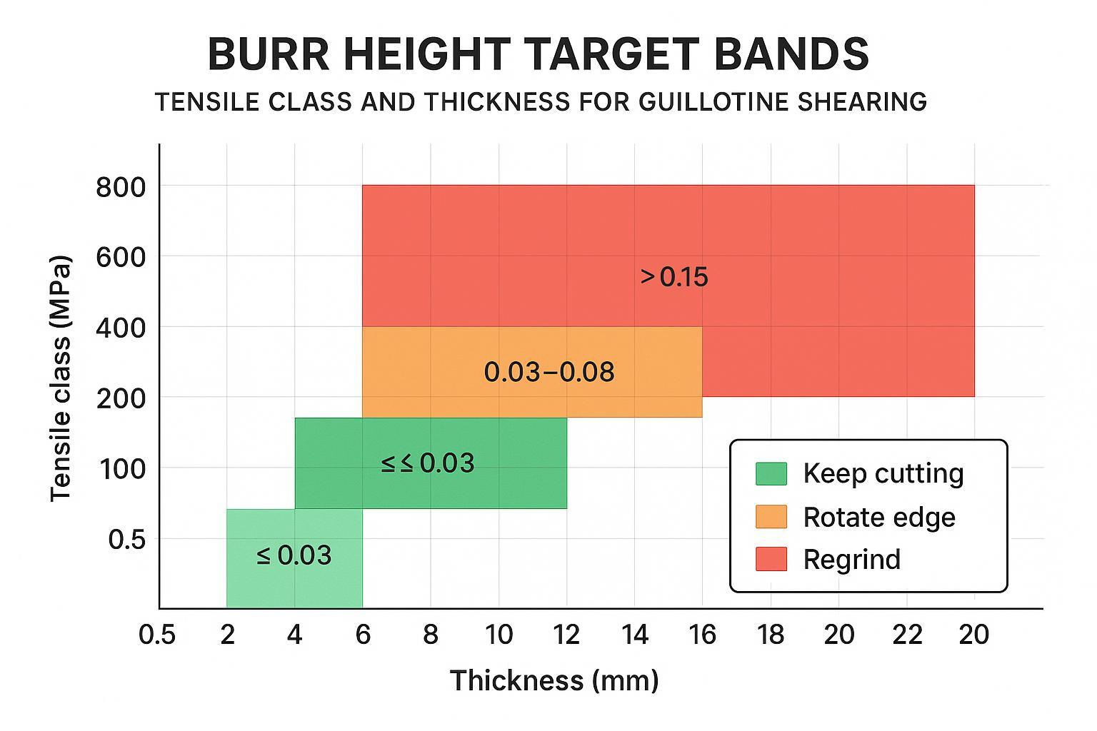
A burr height threshold for shearing only works if it’s tied to an action. Use bands so different shifts don’t make different decisions on the same edge.
Example internal acceptance criteria (not an international standard)
Below is an example of internal burr-height limits used in production control. The measurement criteria in the tables below reflect the blade condition thresholds Maxtor Metal references when evaluating shear blade performance during field reviews. Validate and adjust against your OEM guidance, customer requirements, and your own process capability.
(A) Low-carbon steel (≤350 MPa)
| Sheet thickness | Green (keep running) | Amber (rotate next planned stop) | Red (rotate now; if persists after verified clearance → regrind) |
|---|---|---|---|
| 0.8–2 mm | ≤0.05 mm | 0.05–0.10 mm | >0.10 mm |
| 2–6 mm | ≤0.08 mm | 0.08–0.15 mm | >0.15 mm |
| 6–12 mm | ≤0.12 mm | 0.12–0.20 mm | >0.20 mm |
(B) High-strength steel (350–700 MPa)
Because of springback and a larger fracture zone, limits are often tightened/shifted.
| Sheet thickness | Green (keep running) | Amber (rotate next planned stop) | Red (rotate now; if persists after verified clearance → regrind) |
|---|---|---|---|
| 1–3 mm | ≤0.07 mm | 0.07–0.12 mm | >0.12 mm |
| 3–8 mm | ≤0.10 mm | 0.10–0.18 mm | >0.18 mm |
| 8–15 mm | ≤0.15 mm | 0.15–0.25 mm | >0.25 mm |
Règle de décision
- Green: keep running; log the measurement.
- Amber: rotate at the next planned stop.
- Red: rotate now; if red persists after verified clearance, trigger regrind.
Measurement method (make the data defensible)
- Tooling: a burr gauge or a toolmaker microscope (e.g., 50×), with a defined reading rule.
- Sampling: measure left/center/right, 3 points each (9 readings total); record max, average, and standard deviation.
- Minimum resolution: use an instrument with resolution at least 0,01 mm (preferably finer).
- Repeatability: if multiple shifts measure, run a simple check to confirm different operators obtain comparable readings.
Edge chamfer/hone and visual cues
Burr is not only a clearance problem. A sharp blade with poor gap can burr—but a dull blade with perfect gap can burr too.
Use visual cues that are easy to standardize:
- Reflective bright line along the edge: rounded bevel (edge no longer a crisp line).
- Micro-chipping: repeating burr “spikes” along the cut length.
- Double cut/step: frequently correlates with clearance too tight (verify before regrind).
Sampling and measurement method
If you want burr data you can defend, standardize sampling and the measuring tool.
Sampling cadence (simple default)
- Once per shift per active shear, and once immediately after any clearance change or rotation.
What to record
- Material family + thickness
- Clearance target and measured left/center/right
- Burr height (max observed) + method
- Operator/shift and action taken
Avoid “looks OK.” If you don’t have a dedicated burr gauge, use a consistent comparator method until you do.
Planning de rotation et journaux de bord
Edge-use sequence (four sides)
A 4-edge blade only pays off if your rotation order is standardized.

Recommended rule: rotate in a fixed sequence (Edge 1 → 2 → 3 → 4). If you skip an edge due to a nick, document it and why. A fixed rotation order prevents accidental reuse of a degraded edge and makes the log unambiguous—if you always rotate 1→2→3→4, any out-of-sequence entry is immediately visible as an anomaly.
Rotation “done when…”
- Clearance verified left/center/right
- One controlled test cut inspected
- Log updated (edge number, date, cut count estimate)
Shift-level inspection cadence
A practical cadence for mixed steels:
- Start of shift / job change: quick edge visual check + verify the last recorded clearance basis matches the job.
- During production: burr sample at the defined interval; record any change in cut sound as a note.
- End of shift: decision logged (keep / rotate / pull for regrind).
Rotation record template essentials
Your rotation record is the backbone of traceability—and the easiest place for gaps to hide.
Minimum fields (audit-ready)
- Blade set ID, machine ID
- Edge number in use (1–4)
- Material mix (thickness range + tensile class)
- Clearance target + measured left/center/right
- Burr height + measurement method
- Decision and sign-off
Two fields that make the log useful for cost and planning:
- Estimated cut count or runtime
- nombre de rebroyés
That set of fields is enough to be a reversible shear blade rotation log that quality and maintenance can both use.
Critères de réaffûtage et contrôle d'affûtage
Triggers and minimum removal
Regrind is a controlled response to sustained indicators—not the first reaction.
Trigger regrind when BOTH are true
- Burr stays in your red band, and
- Clearance has been verified (left/center/right) and corrected, but burr remains above limit.
Also trigger regrind (or replacement) for chips, cracks, or if the blade has reached OEM minimum dimensions. When chips are the trigger, the fracture mode — fatigue versus impact — determines whether the corrective action is a clearance adjustment or a hardness and grade change. Misidentifying the mode leads to repeat chipping after the next regrind cycle. The Shear Blade Edge Chipping Root Cause Analysis: Fractography and Decision Tree provides the shop-floor reading method and the corresponding SOP corrections.
On minimum removal: remove only what’s needed to restore a continuous edge and the correct bevel. Heavy passes shorten total life.
Preserve geometry and tolerances
Your shear blade regrind criteria should protect geometry first—because geometry drift forces clearance changes, and clearance changes drive burr.
In neutral technical terms (and consistent with how Maxtor Metal approaches precision grinding work):
- Track OEM minimum dimensions and allowable tolerances as controlled limits.
- Control grinding heat; heat tint/discoloration is a reject signal.
- Verify straightness and thickness consistency across the full length.
- Lightly hone/deburr after grinding to avoid installing a fragile burr that breaks off into product.
Post-grind checkpoints to standardize:
- No heat tint on the edge
- Straightness/flatness verified (straight edge or dial indicator method)
- Thickness checked at multiple points (micrometer)
Industry practice for post-grind dimensional tolerances typically targets thickness parallelism within 0.05 mm end-to-end and thickness variation ≤0.025 mm per 300 mm of blade length—confirm against your OEM’s stated limits. Maxtor Metal’s post-grind inspection protocol includes heat-tint verification, full-length straightness measurement, and micrometer-based thickness mapping at five positions before any reground blade is released from production. If regrind intervals remain short despite disciplined geometry control, the underlying blade grade may be the constraint — the carbide microstructure and failure-mode selection framework between D2 and SKD11 is covered in the D2 vs SKD11 tool steel selection guide for shearing blades.
For operations where regrind frequency is the primary cost driver—particularly on AHSS or coated materials—switching to a carbide-inlaid blade construction can significantly extend edge life between regrind events. A full cost-per-meter model and pilot benchmark data are available in the Tungsten Carbide Inlaid Shear Blades ROI Guide for AHSS.
Post-grind installation checks
After reinstalling a reground set:
- Clean seats, torque to spec, verify clearance left/center/right.
- Run a test cut and measure burr.
- Record the baseline so the next shift isn’t guessing.
For the full shim stack calculation method after regrind, see the regrinding thickness reduction compensation and shim stack guide.
Charge moteur comme signal de corroboration

Baseline current profile
Motor load/current won’t replace burr or clearance checks, but it can corroborate rising cutting resistance.
Start with a baseline:
- Use VFD/drive readings or installed sensors.
- Baseline by material family and thickness band.
- Trend over weeks, not one day.
Le ReliaMag note on baselining and trending motor current captures the key pitfall: without baselines, trending, and thresholds, current data is just noise.
Alert bands and safe monitoring
Set alert bands relative to your own baseline and validate them on known-good runs.
If you use current transformers, follow CT safety rules: NK Technologies’ guidance on current monitoring for predictive maintenance notes that CT secondaries must not be left open-circuit when energized.
Correlation with burr and clearance
Use current as a cross-check:
- Rising current + rising burr + verified clearance drift → fix setup first.
- Rising current + stable burr → check hold-down, alignment, lubrication, or mechanical drag.
- Stable current + rising burr → likely edge geometry/dullness.
Documentation et conformité
Contrôle des versions, portée et note de sécurité
Document control
- SOP / Work instruction title: 4-edge reversible blade rotation schedule and regrind criteria
- Document owner: Maintenance / Quality
- Version: v1.0
- Effective date: 2026-07-02
- Review cadence: quarterly (or after any OEM/manual revision)
Revision log (template)
| Version | Date | Changed by | Summary of change |
|---|---|---|---|
| v1.0 | 2026-07-02 | Initial release |
Scope & applicability
This protocol is a best-practice framework for guillotine shears using reversible multi-edge (4-edge) blades on 0.5–20 mm carbon, stainless, and high-strength steels.
Safety & responsibility disclaimer
- This document does not replace your machine OEM manual, lockout/tagout procedures, or site EHS requirements.
- OEM limits and instructions always take precedence (minimum dimensions, allowable straightness/flatness, torque, blade gap/clearance range, and inspection intervals).
- Blade handling and clearance adjustments should be performed only by trained/qualified personnel with appropriate PPE and guarding in place.
- If there is any conflict between this protocol and an OEM manual, follow the OEM manual and record the deviation in the log.
Rotation and regrind traceability
Minimum traceability pack per blade set:
- Blade ID and spec (where available)
- Rotation log (edge usage history)
- Regrind log (date, key checks, pass/fail)
- Nonconformance notes (what happened, what was corrected)
OEM-dependent limits and audits
Write into the SOP that OEM limits win:
- Minimum blade dimensions after regrinds
- Straightness/flatness limits
- Hole/seat wear limits
Attach OEM charts/manual pages as controlled documents (with revision) if your quality system requires it.
Training and continuous improvement
Train for consistency:
- clearance measurement left/center/right
- double-cut vs tearing identification
- burr measurement and recording
- rotate vs regrind decision logic
Then review logs monthly to adjust burr bands to your downstream requirements—not to opinion.
Références et manuels d'assistance (sélectionnés)
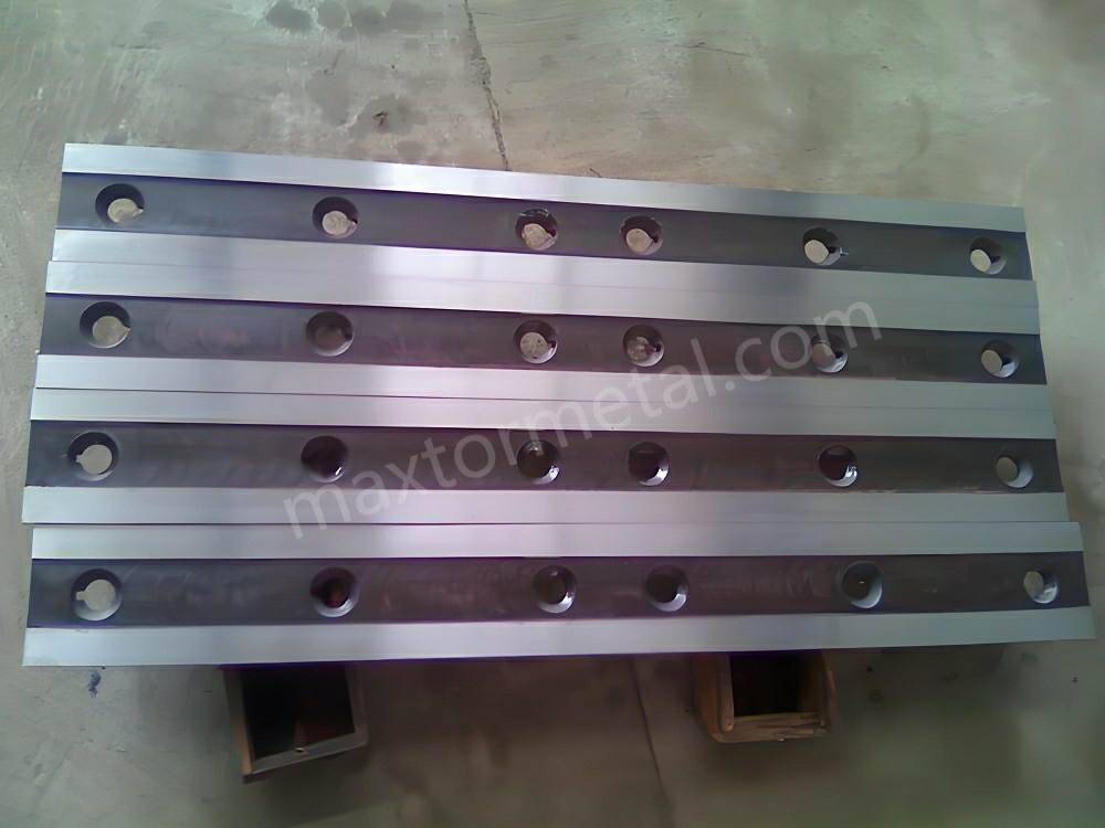
The following publicly available resources support the maintenance philosophy in this article (multi-edge rotation, resetting blade gap after turning/sharpening, and controlling regrind tolerances). Always verify applicability to your specific shear model.
- Tennsmith LM/MSE Series Operation & Maintenance Manual — four-edge blades, factory-set clearance example, and the requirement to reset clearance after turning to a new edge or after re-sharpening: https://www.trick-tools.com/common/documentation/mse1016-manual.pdf
- Genesis GXP Mobile Shear manual excerpt (demolition/mobile shear context; useful for multi-edge rotation mindset and inspection intervals such as 40–80 hours rotation guidance et rotation when edge radius reaches 1/8 in (3 mm)): https://www.andersonequip.com/web/files/MfrModelDocs/GEM-GXP-broc.pdf
Étude de cas (exemple)
The following case example is drawn from a maintenance review conducted with a Maxtor Metal D2 shear blade customer. Customer identity anonymized per standard disclosure practice.
Contexte
- Factory: automotive parts stamping center (anonymous)
- Machine: 3200 mm hydraulic guillotine shear
- Blade: 4-edge reversible D2 shear blades (vacuum heat-treated, 3200 mm, supplied by Maxtor Metal)
- Material: ASTM A36, 4 mm
- Operation: two shifts/year-round
Results represent a single documented maintenance trial; outcomes may vary by machine type, material grade, and operating conditions.
Before (no standardized rotation schedule)
- Rotation triggered inconsistently when burr “looked bad”
- Uneven utilization across edges (Edge 1 over-used; Edge 2 nearly new; Edge 3/4 inconsistent)
- No rotation log
After (measurement-based schedule + rotation log)
Inspection every 120–150 operating hours (interval established from baseline wear data collected during the first two months of the trial; adjust to your actual wear curve and OEM guidance), recording:
- Edge No.
- Operating hours
- Burr height
- Edge radius
- Operator
Rotate when any of the following occurs:
- Burr > 0.10 mm
- Edge radius ≈ 0.20–0.30 mm
- Cut sound changes noticeably
- Burnished zone increases visibly
Measurement sequence for the first piece each shift:
- Tooling: 50× toolmaker microscope + burr gauge
- Method: left/center/right, 3 points each (9 readings total); record max/avg/std dev; trend for 3 shifts
Résultats
| Métrique | Avant | After (4-month average) |
|---|---|---|
| Max burr | 0.18 mm | 0.09 mm |
| Average burr | 0.11 mm | 0.05 mm |
| Unplanned blade changes | 5 / month | 2 / month |
| Blade removals/installs | 9 / month | 6 / month |
| Taux de rebut | 2.3% | 1.1% |
| TRG (Taux de Rendement Global) | 82.4% | 85.6% |
Note: The burr-height thresholds and rotation intervals shown above represent an example of an internal production standard for a 4 mm low-carbon steel application. Actual acceptance limits should be validated against the machine OEM recommendations, customer quality requirements, material grade, and sheet thickness.
Conclusion
A 4-edge reversible blade gives you four chances to stay ahead of burr and downtime—if you manage it like a controlled process.
Tie actions to quantified thresholds: verify clearance, measure burr, rotate to the next edge first, and regrind only when limits persist across a verified setup. Done well, this stabilizes cut quality, extends rotation and regrind intervals, lowers TCO, and protects OEE.
That’s why Maxtor Metal includes rotation log templates and regrind criteria checklists in its blade maintenance documentation—the measurement discipline is built into the delivery, not left to be reconstructed at the machine.
If you want a reference point for the blade type discussed here, see the Maxtor Metal precision shear blades for guillotine applications for tooling specifications and contact options.
FAQs:
Q: Quel est un bon point de départ pour le jeu des couteaux d'une cisaille guillotine ?
A common baseline is around 7% of material thickness, then adjust for material strength and actual edge results. The Shear Fundamentals training note explains both the baseline and the failure modes.
Q: Comment savoir si les bavures sont causées par le jeu ou par un couteau émoussé ?
R: Vérifiez d'abord le jeu à gauche, au centre et à droite. Si la bavure reste importante après une correction vérifiée, suspectez la géométrie du tranchant (biseau arrondi, micro-ébréchures). Un « double coup/marche » indique un jeu troppo serré ; un déchirement et une bavure épaisse indiquent souvent un jeu trop large.
Q: Quand dois-je effectuer la rotation d'une lame de cisaille réversibles à 4 côtés ?
R: Effectuez la rotation lorsque la bavure entre dans la "zone orange/alerte" (ou dès l'apparition d'un arrondi précoce de l'arête) afin de pouvoir planifier l'intervention lors d'un arrêt programmé. La rotation est moins coûteuse que le réaffûtage et préserve l'OEE.
Q: Quand dois-je réaffûter plutôt que de faire pivoter la lame ?
R: Réaffûtez lorsque la bavure reste supérieure à la limite après avoir (1) pivoté vers une arête neuve et (2) vérifié le jeu et le parallélisme. Réaffûtez ou remplacez également en cas d'ébréchures, de fissures ou lorsque les dimensions minimales de l'OEM sont atteintes.
Q: Que doit inclure un journal de rotation pour être prêt pour un audit ?
R: ID du couteau, ID de la machine, numéro de l'arête, classe/épaisseur du matériau, jeu cible + mesuré gauche/centre/droite, hauteur de bavure + méthode, action entreprise et émargement. Ajoutez le nombre de coupes/temps de fonctionnement et le nombre de réaffûtages pour l'analyse du TCO.
Q: Le contrôle de la intensité du moteur peut-il remplacer la vérification des bavures et du jeu ?
R: Non. L'intensité est un signal de corroboration et un indicateur de tendance. Elle peut signaler tôt une augmentation de la résistance à la coupe, mais elle ne peut pas diagnostiquer une dérive du jeu par rapport à la géométrie de l'arête sans contrôles physiques.
Auteur
Jesse Xu — Senior Quality Engineer, QA (Quality Assurance), Maxtor Metal
- Experience: 15 years in industrial blade quality assurance and failure analysis
- Focus: diagnosing edge chipping and abnormal wear; distinguishing heat-treatment issues vs. material segregation
- Certifications: ASQ-CQE, ISO 9001 Lead Auditor, ASNT Level II

 English
  Spanish
  Italian
  French
  Portuguese
  Russian
  German
  Arabic
  Hindi
Hindi  Vietnamese
  Indonesian
  Japanese
  Korean