

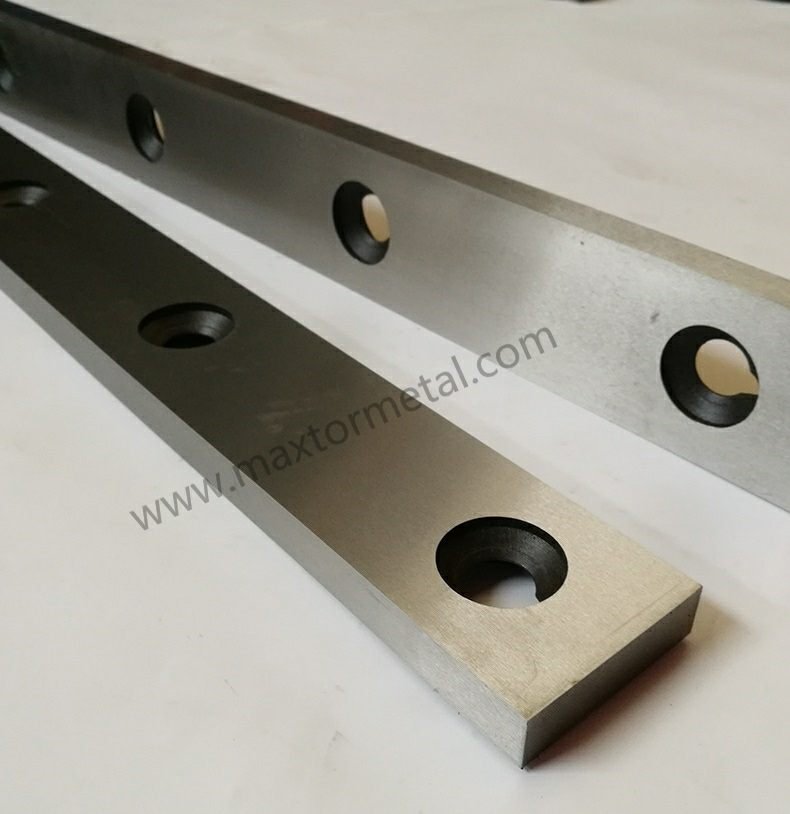
炭素鋼、不锈钢(ステンレス)、高張力鋼(ハイテン材)などが混在するラインでシャーリングマシンを稼働させている場合、次のような典型的なトラブルパターンをすでにご存知のはずです。バリが徐々に大きくなり、現場のオペレーターはクリアランス設定の「後追い調整」に追われ、結果として非計画的なライン停止(突発的なダウンタイム)に見舞われることになります。
本稿では、4面使える割出型(リバーシブル)替刃のデータ測定に基づく運用プロトコルを定義します(反転のタイミング、再研磨のトリガー、および第三者監査に対応するための記録項目について)。なお、背景情報の共有として(営業ピッチではありません)、この刃物カテゴリーは Maxtor Metalのシャーリングナイフ製品ページに掲載されています。.
- Objective: define a data-driven 4-edge reversible blade rotation schedule and regrind criteria.
- KPIs: burr height, clearance accuracy, edge geometry, OEE/TCO impact, safety.
- Scope: 0.5–20 mm carbon, stainless, and high-strength steels; third-party audit ready.
技術ノート: Di Maxtor Metal, pisau potong pelat (guillotine shear blades) yang dipasok untuk penggunaan material campuran didokumentasikan dengan data kelurusan dan ketebalan yang diukur di pabrik, memungkinkan garis dasar celah (clearance baseline) dikaitkan dengan geometri pisau yang sebenarnya, bukan spesifikasi nominal. Maxtor Metalせん断刃の技術概要を参照してください。]
クリアランス設定の基本
Baseline and material factors
A consistent guillotine shear blade clearance setup starts with a baseline and a disciplined way to adjust it as material strength changes.
A widely adopted baseline for guillotine shear clearance is ~7% of material thickness, with two directional failure modes that define the usable window:
- Too much clearance → tearing and burr.
- Too little clearance → a double cut/step.
重要: Treat ~7% as a starting reference, not a universal specification. The valid clearance window depends on the machine, blade condition, and the material’s strength and thickness—and must be verified on your specific shear by measuring left/center/right and confirming with controlled test cuts.
Where available, record and follow your OEM’s stated blade-gap guidance. For example, the Tennsmith LM/MSE manual notes a factory-set blade clearance of .003 in at the ends and .002 in at the center, and emphasizes that clearance must be reset after turning to a new edge or after re-sharpening (Tennsmith MSE1016 Operation & Maintenance Manual; see References section).
Setting and verifying the gap
Treat clearance as a measured setting, not a knob position.
Minimum tool kit
- Feeler gauges (clean, undamaged)
- Micrometer/caliper (material thickness + blade checks)
- Dial indicator (parallelism checks)
- Clean shims (if your shear uses shim packs)
Verification sequence (repeatable, audit-friendly)
- Isolate/lock off the machine and confirm guards/hold-downs are safe.
- Clean blade seats and clamping faces (chips under a seat behave like “bad clearance”).
- Measure actual sheet thickness (don’t trust nominal).
- Set target clearance and record the basis (thickness + material class).
- Verify clearance at left/center/right with a feeler gauge.
- Run a short test cut on representative scrap and inspect the edge.
重要なポイント: If left/center/right don’t agree, your “clearance” is three different clearances.
For a step-by-step calibration checklist (parallelism first, then clearance), Maxtor Metal’s guillotine blade setup guide on calibrating parallelism and clearance 参考になる資料です。
Compensating after regrind
Regrinding changes installed geometry and seating height. Your protocol should treat “post-regrind install” as a controlled setup event:
- Clean seats, verify torque, then re-check clearance at left/center/right.
- Record the measured values as the new baseline.
- Confirm with a test cut before releasing to production.
The burr-height bands in the tables below reflect the measurement criteria Maxtor Metal uses when evaluating blade condition during field audits for shear blade customers.
バリの許容閾値と刃先幾何形状
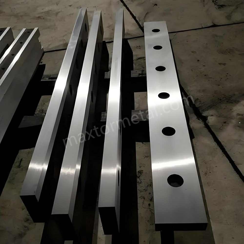
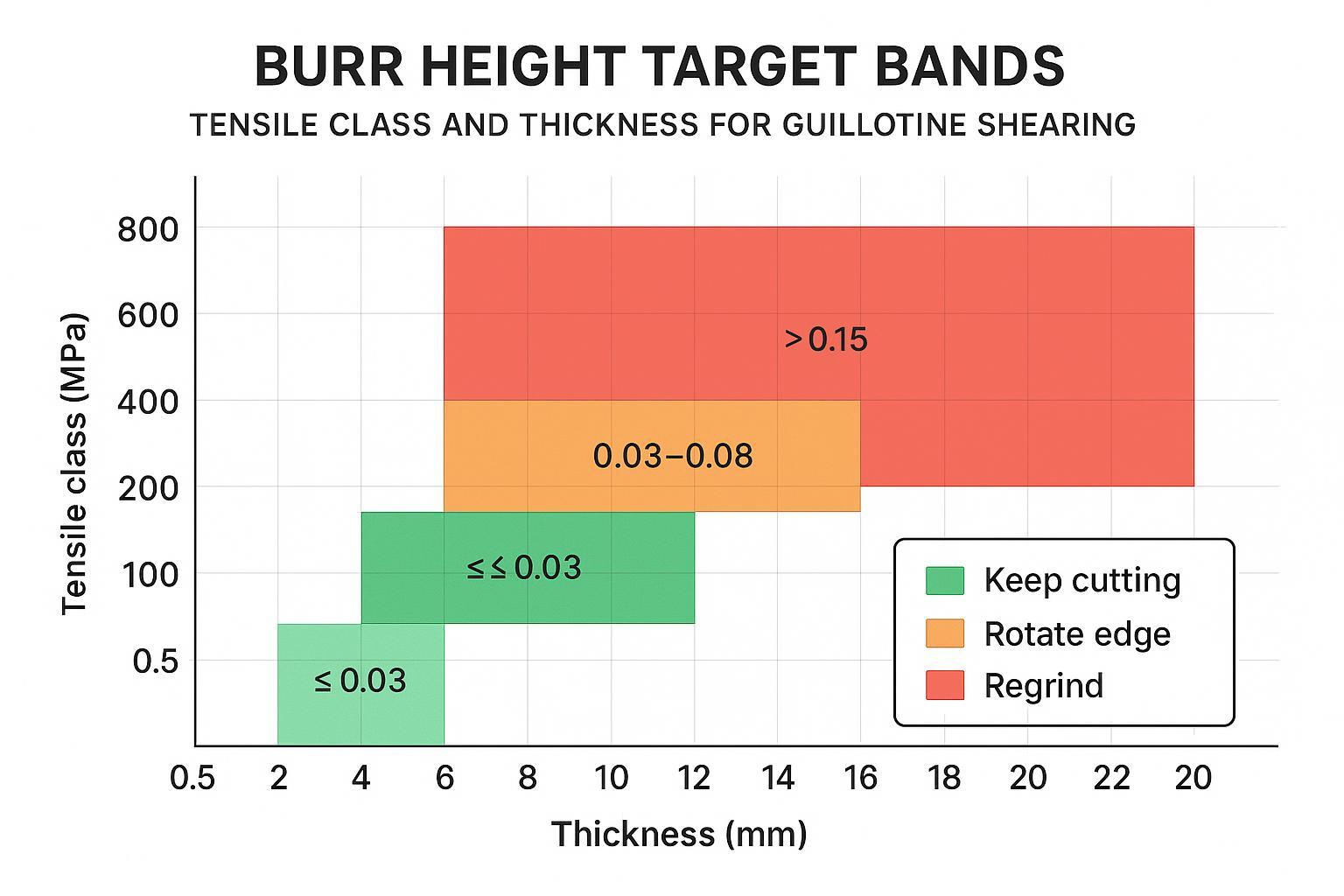
Burr height bands by thickness and strength
A burr height threshold for shearing only works if it’s tied to an action. Use bands so different shifts don’t make different decisions on the same edge.
Example internal acceptance criteria (not an international standard)
Below is an example of internal burr-height limits used in production control. The measurement criteria in the tables below reflect the blade condition thresholds Maxtor Metal references when evaluating shear blade performance during field reviews. Validate and adjust against your OEM guidance, customer requirements, and your own process capability.
(A) Low-carbon steel (≤350 MPa)
| Sheet thickness | Green (keep running) | Amber (rotate next planned stop) | Red (rotate now; if persists after verified clearance → regrind) |
|---|---|---|---|
| 0.8–2 mm | ≤0.05 mm | 0.05–0.10 mm | >0.10 mm |
| 2–6 mm | ≤0.08 mm | 0.08–0.15 mm | >0.15 mm |
| 6–12 mm | ≤0.12 mm | 0.12–0.20 mm | >0.20 mm |
(B) High-strength steel (350–700 MPa)
Because of springback and a larger fracture zone, limits are often tightened/shifted.
| Sheet thickness | Green (keep running) | Amber (rotate next planned stop) | Red (rotate now; if persists after verified clearance → regrind) |
|---|---|---|---|
| 1–3 mm | ≤0.07 mm | 0.07–0.12 mm | >0.12 mm |
| 3–8 mm | ≤0.10 mm | 0.10–0.18 mm | >0.18 mm |
| 8–15 mm | ≤0.15 mm | 0.15–0.25 mm | >0.25 mm |
Decision rule
- Green: keep running; log the measurement.
- Amber: rotate at the next planned stop.
- Red: rotate now; if red persists after verified clearance, trigger regrind.
Measurement method (make the data defensible)
- Tooling: a burr gauge or a toolmaker microscope (e.g., 50×), with a defined reading rule.
- Sampling: measure left/center/right, 3 points each (9 readings total); record max, average, and standard deviation.
- Minimum resolution: use an instrument with resolution at least 0.01ミリメートル (preferably finer).
- Repeatability: if multiple shifts measure, run a simple check to confirm different operators obtain comparable readings.
Edge chamfer/hone and visual cues
Burr is not only a clearance problem. A sharp blade with poor gap can burr—but a dull blade with perfect gap can burr too.
Use visual cues that are easy to standardize:
- Reflective bright line along the edge: rounded bevel (edge no longer a crisp line).
- マイクロチッピング(微小欠け): repeating burr “spikes” along the cut length.
- Double cut/step: frequently correlates with clearance too tight (verify before regrind).
Sampling and measurement method
If you want burr data you can defend, standardize sampling and the measuring tool.
Sampling cadence (simple default)
- Once per shift per active shear, and once immediately after any clearance change or rotation.
What to record
- Material family + thickness
- Clearance target and measured left/center/right
- Burr height (max observed) + method
- Operator/shift and action taken
Avoid “looks OK.” If you don’t have a dedicated burr gauge, use a consistent comparator method until you do.
刃物の反転スケジュールと履歴ログ
Edge-use sequence (four sides)
A 4-edge blade only pays off if your rotation order is standardized.

Recommended rule: rotate in a fixed sequence (Edge 1 → 2 → 3 → 4). If you skip an edge due to a nick, document it and why. A fixed rotation order prevents accidental reuse of a degraded edge and makes the log unambiguous—if you always rotate 1→2→3→4, any out-of-sequence entry is immediately visible as an anomaly.
Rotation “done when…”
- Clearance verified left/center/right
- One controlled test cut inspected
- Log updated (edge number, date, cut count estimate)
Shift-level inspection cadence
A practical cadence for mixed steels:
- Start of shift / job change: quick edge visual check + verify the last recorded clearance basis matches the job.
- During production: burr sample at the defined interval; record any change in cut sound as a note.
- End of shift: decision logged (keep / rotate / pull for regrind).
Rotation record template essentials
Your rotation record is the backbone of traceability—and the easiest place for gaps to hide.
Minimum fields (audit-ready)
- Blade set ID, machine ID
- Edge number in use (1–4)
- Material mix (thickness range + tensile class)
- Clearance target + measured left/center/right
- Burr height + measurement method
- Decision and sign-off
Two fields that make the log useful for cost and planning:
- Estimated cut count or runtime
- Regrind count
That set of fields is enough to be a reversible shear blade rotation log that quality and maintenance can both use.
再研磨基準と研削管理
Triggers and minimum removal
Regrind is a controlled response to sustained indicators—not the first reaction.
Trigger regrind when BOTH are true
- Burr stays in your red band, and
- Clearance has been verified (left/center/right) and corrected, but burr remains above limit.
Also trigger regrind (or replacement) for chips, cracks, or if the blade has reached OEM minimum dimensions. When chips are the trigger, the fracture mode — fatigue versus impact — determines whether the corrective action is a clearance adjustment or a hardness and grade change. Misidentifying the mode leads to repeat chipping after the next regrind cycle. The Shear Blade Edge Chipping Root Cause Analysis: Fractography and Decision Tree provides the shop-floor reading method and the corresponding SOP corrections.
On minimum removal: remove only what’s needed to restore a continuous edge and the correct bevel. Heavy passes shorten total life.
Preserve geometry and tolerances
Your shear blade regrind criteria should protect geometry first—because geometry drift forces clearance changes, and clearance changes drive burr.
In neutral technical terms (and consistent with how Maxtor Metal approaches precision grinding work):
- Track OEM minimum dimensions and allowable tolerances as controlled limits.
- Control grinding heat; heat tint/discoloration is a reject signal.
- Verify straightness and thickness consistency across the full length.
- Lightly hone/deburr after grinding to avoid installing a fragile burr that breaks off into product.
Post-grind checkpoints to standardize:
- No heat tint on the edge
- Straightness/flatness verified (straight edge or dial indicator method)
- Thickness checked at multiple points (micrometer)
Industry practice for post-grind dimensional tolerances typically targets thickness parallelism within 0.05 mm end-to-end and thickness variation ≤0.025 mm per 300 mm of blade length—confirm against your OEM’s stated limits. Maxtor Metal’s post-grind inspection protocol includes heat-tint verification, full-length straightness measurement, and micrometer-based thickness mapping at five positions before any reground blade is released from production. If regrind intervals remain short despite disciplined geometry control, the underlying blade grade may be the constraint — the carbide microstructure and failure-mode selection framework between D2 and SKD11 is covered in the D2 vs SKD11 tool steel selection guide for shearing blades.
For operations where regrind frequency is the primary cost driver—particularly on AHSS or coated materials—switching to a carbide-inlaid blade construction can significantly extend edge life between regrind events. A full cost-per-meter model and pilot benchmark data are available in the タングステンカーバイド象嵌せん断刃のAHSS向け投資対効果ガイド.
Post-grind installation checks
After reinstalling a reground set:
- Clean seats, torque to spec, verify clearance left/center/right.
- Run a test cut and measure burr.
- Record the baseline so the next shift isn’t guessing.
For the full shim stack calculation method after regrind, see the regrinding thickness reduction compensation and shim stack guide.
刃物摩耗の補完シグナルとしてのモータ負荷

Baseline current profile
Motor load/current won’t replace burr or clearance checks, but it can corroborate rising cutting resistance.
Start with a baseline:
- Use VFD/drive readings or installed sensors.
- Baseline by material family and thickness band.
- Trend over weeks, not one day.
の ReliaMag note on baselining and trending motor current captures the key pitfall: without baselines, trending, and thresholds, current data is just noise.
Alert bands and safe monitoring
Set alert bands relative to your own baseline and validate them on known-good runs.
If you use current transformers, follow CT safety rules: NK Technologies’ guidance on current monitoring for predictive maintenance notes that CT secondaries must not be left open-circuit when energized.
Correlation with burr and clearance
Use current as a cross-check:
- Rising current + rising burr + verified clearance drift → fix setup first.
- Rising current + stable burr → check hold-down, alignment, lubrication, or mechanical drag.
- Stable current + rising burr → likely edge geometry/dullness.
文書化およびコンプライアンス(品質適合)
改訂履歴(バージョン管理)、適用範囲、および安全上の注意
Document control
- SOP / Work instruction title: 4-edge reversible blade rotation schedule and regrind criteria
- Document owner: Maintenance / Quality
- Version: v1.0
- Effective date: 2026-07-02
- Review cadence: quarterly (or after any OEM/manual revision)
Revision log (template)
| Version | 日付 | Changed by | Summary of change |
|---|---|---|---|
| v1.0 | 2026-07-02 | Initial release |
Scope & applicability
This protocol is a best-practice framework for guillotine shears using reversible multi-edge (4-edge) blades on 0.5–20 mm carbon, stainless, and high-strength steels.
Safety & responsibility disclaimer
- This document does not replace your machine OEM manual, lockout/tagout procedures, or site EHS requirements.
- OEM limits and instructions always take precedence (minimum dimensions, allowable straightness/flatness, torque, blade gap/clearance range, and inspection intervals).
- Blade handling and clearance adjustments should be performed only by trained/qualified personnel with appropriate PPE and guarding in place.
- If there is any conflict between this protocol and an OEM manual, follow the OEM manual and record the deviation in the log.
Rotation and regrind traceability
Minimum traceability pack per blade set:
- Blade ID and spec (where available)
- Rotation log (edge usage history)
- Regrind log (date, key checks, pass/fail)
- Nonconformance notes (what happened, what was corrected)
OEM-dependent limits and audits
Write into the SOP that OEM limits win:
- Minimum blade dimensions after regrinds
- Straightness/flatness limits
- Hole/seat wear limits
Attach OEM charts/manual pages as controlled documents (with revision) if your quality system requires it.
Training and continuous improvement
Train for consistency:
- clearance measurement left/center/right
- double-cut vs tearing identification
- burr measurement and recording
- rotate vs regrind decision logic
Then review logs monthly to adjust burr bands to your downstream requirements—not to opinion.
参考文献および関連マニュアル(抜粋)
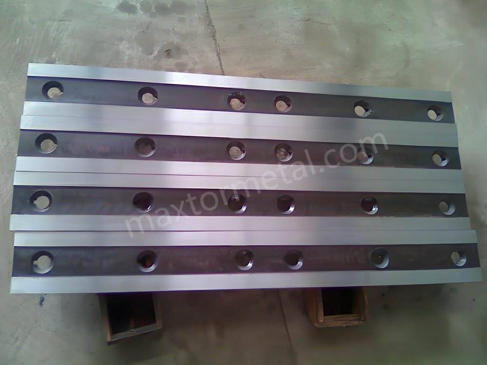
The following publicly available resources support the maintenance philosophy in this article (multi-edge rotation, resetting blade gap after turning/sharpening, and controlling regrind tolerances). Always verify applicability to your specific shear model.
- Tennsmith LM/MSE Series Operation & Maintenance Manual — four-edge blades, factory-set clearance example, and the requirement to reset clearance after turning to a new edge or after re-sharpening: https://www.trick-tools.com/common/documentation/mse1016-manual.pdf
- Genesis GXP Mobile Shear manual excerpt (demolition/mobile shear context; useful for multi-edge rotation mindset and inspection intervals such as 40–80 hours rotation guidance そして rotation when edge radius reaches 1/8 in (3 mm)): https://www.andersonequip.com/web/files/MfrModelDocs/GEM-GXP-broc.pdf
事例研究 / ケーススタディ(導入事例)
The following case example is drawn from a maintenance review conducted with a Maxtor Metal D2 shear blade customer. Customer identity anonymized per standard disclosure practice.
コンテクスト
- Factory: automotive parts stamping center (anonymous)
- Machine: 3200 mm hydraulic guillotine shear
- Blade: 4-edge reversible D2 shear blades (vacuum heat-treated, 3200 mm, supplied by Maxtor Metal)
- Material: ASTM A36, 4 mm
- Operation: two shifts/year-round
Results represent a single documented maintenance trial; outcomes may vary by machine type, material grade, and operating conditions.
Before (no standardized rotation schedule)
- Rotation triggered inconsistently when burr “looked bad”
- Uneven utilization across edges (Edge 1 over-used; Edge 2 nearly new; Edge 3/4 inconsistent)
- No rotation log
After (measurement-based schedule + rotation log)
Inspection every 120–150 operating hours (interval established from baseline wear data collected during the first two months of the trial; adjust to your actual wear curve and OEM guidance), recording:
- Edge No.
- Operating hours
- バリの高さ
- 刃先R(エッジ半径)
- オペレーター
Rotate when any of the following occurs:
- Burr > 0.10 mm
- Edge radius ≈ 0.20–0.30 mm
- Cut sound changes noticeably
- Burnished zone increases visibly
Measurement sequence for the first piece each shift:
- Tooling: 50× toolmaker microscope + burr gauge
- Method: left/center/right, 3 points each (9 readings total); record max/avg/std dev; trend for 3 shifts
結果
| メトリック | 前に | After (4-month average) |
|---|---|---|
| マックスバー | 0.18 mm | 0.09 mm |
| 平均的なバリ | 0.11 mm | 0.05 mm |
| Unplanned blade changes | 5 / month | 2 / month |
| Blade removals/installs | 9 / month | 6 / month |
| スクラップ率 | 2.3% | 1.1% |
| OEE | 82.4% | 85.6% |
注記: The burr-height thresholds and rotation intervals shown above represent an example of an internal production standard for a 4 mm low-carbon steel application. Actual acceptance limits should be validated against the machine OEM recommendations, customer quality requirements, material grade, and sheet thickness.
結論
A 4-edge reversible blade gives you four chances to stay ahead of burr and downtime—if you manage it like a controlled process.
Tie actions to quantified thresholds: verify clearance, measure burr, rotate to the next edge first, and regrind only when limits persist across a verified setup. Done well, this stabilizes cut quality, extends rotation and regrind intervals, lowers TCO, and protects OEE.
That’s why Maxtor Metal includes rotation log templates and regrind criteria checklists in its blade maintenance documentation—the measurement discipline is built into the delivery, not left to be reconstructed at the machine.
If you want a reference point for the blade type discussed here, see the Maxtor Metal precision shear blades for guillotine applications for tooling specifications and contact options.
FAQs:
Q: シャーリングマシンのクリアランス(刃口間隙)設定は、まずどの数値を基準にすべきですか?
A common baseline is around 7% of material thickness, then adjust for material strength and actual edge results. The Shear Fundamentals training note explains both the baseline and the failure modes.
Q: バリの発生原因が、クリアランス設定の不適切によるものか、刃物の摩耗(刃鈍り)によるものかを見分けるにはどうすればよいですか?
A: まず、刃の「左・中央・右」の3点でクリアランスを実測・検証してください。調整後もバリが改善されない場合は、刃先幾何形状の異常(ベベルの丸まり、微小なチッピング)が疑われます。切断面に「二重せん断面(ダブルカット)や段差」がある場合はクリアランスが狭すぎ、被削材の「引きちぎり(むしれ)や重度のバリ」がある場合はクリアランスが広すぎる傾向にあります。
Q: 4面使える割出型(リバーシブル)シャーリングナイフを反転・交換する適切なタイミングはいつですか?
A: バリの大きさが管理値の「黄信号(アンバーバンド)」に入った時点(または刃先の丸まりが目視され始めた初期段階)で反転を行ってください。これにより、計画停止のタイミングで安全に作業を消化できます。刃の反転は再研磨に出すよりもコストが圧倒的に低く、設備の総合効率(OEE)を高く維持するのに貢献します。
Q: 刃物の反転ではなく、研磨(再研磨)を行うべき基準は何ですか?
A: ①未使用の刃面に反転し、②クリアランスおよび平行度を検証・調整したお、依然としてバリの大きさが許容値を超える場合は再研磨が必要です。また、刃先にチッピング(刃こぼれ)やクラック(亀裂)が発生している場合、あるいはOEM(原厂)の規定摩耗限界寸法に達した際も、再研磨または新品への交換を行ってください。
Q: 監査に対応するため、刃物の反転履歴(ローテーションログ)にはどのような項目を記載すべきですか?
A: 刃物ID、設備ID、使用刃面番号、被削材の材質/板厚、目標クリアランス値+実測値(左・中央・右)、バリの高さ+測定方法、実施した処置、および作業責任者のサインが必要です。さらに、総所有コスト(TCO)分析を行うために、カット回数/稼働時間、および再研磨回数も記録に加えることを推奨します。
Q: モーターの電流値モニタリング(負荷監視)により、バリやクリアランスの物理的なチェックを省略することは可能ですか?
A: いいえ、不可能です。電流値はあくまで裏付けとなる補足信号(トレンド指標)に過ぎません。切断抵抗の上昇を早期に検知することはできますが、物理的な実測なしに、それが「クリアランスの変動(ズレ)」によるものか「刃先幾何形状の摩耗」によるものかを識別・診断することはできません。
著者
ジェシー・シュー — 上級品質エンジニア、QA(品質保証)、Maxtor Metal
- Experience: 15 years in industrial blade quality assurance and failure analysis
- Focus: diagnosing edge chipping and abnormal wear; distinguishing heat-treatment issues vs. material segregation
- Certifications: ASQ-CQE, ISO 9001 Lead Auditor, ASNT Level II

 English
  Spanish
  Italian
  French
  Portuguese
  Russian
  German
  Arabic
  Hindi
Hindi  Vietnamese
  Indonesian
  Japanese
  Korean