

Nếu bạn đang vận hành máy cắt tôn thủy lực (máy cắt guillotine) với các nhóm mác thép hỗn hợp bao gồm thép cacbon, thép không gỉ và thép cường度 cao, bạn đã quá quen thuộc với kịch bản sự cố này: ba-via tăng dần, thợ vận hành phải "chạy theo" để điều chỉnh khe hở cắt, và thời gian dừng máy trở nên hoàn toàn bị động.
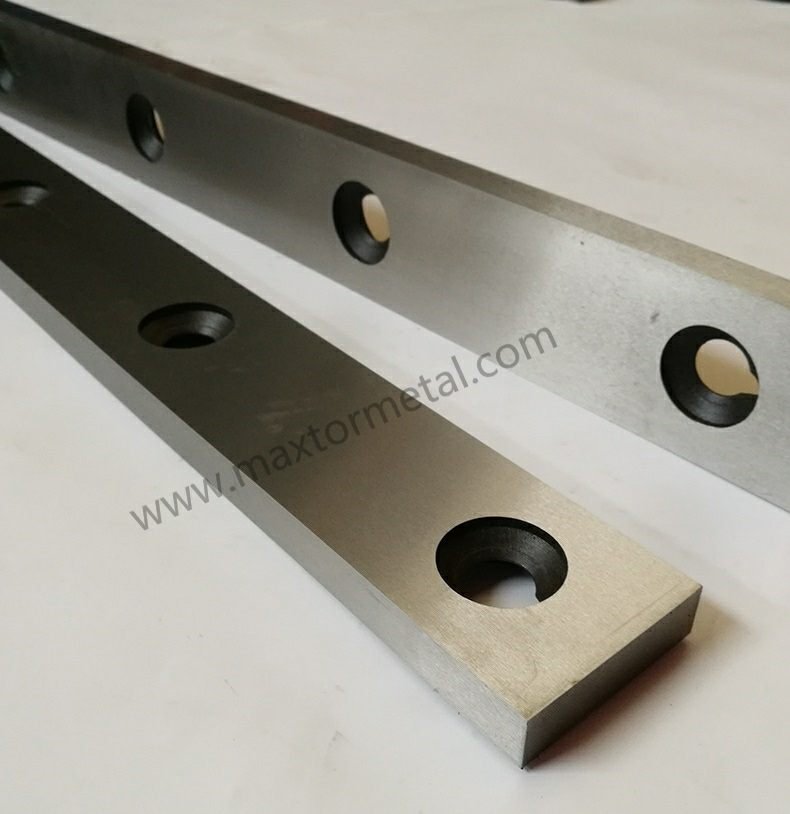
Bài viết này xác định một quy trình dựa trên số liệu đo lường dành cho lưỡi dao cắt lật 4 cạnh—khi nào cần đảo cạnh, khi nào cần mài lại và những gì cần ghi chép nhật ký để quy trình này sẵn sàng đáp ứng các kỳ kiểm toán từ bên thứ ba. Chỉ nhằm mục đích cung cấp ngữ cảnh (không mang tính chất quảng cáo), danh mục dao này được hiển thị trên trang sản phẩm dao cắt tôn thủy lực của Maxtor Metal..
- Objective: define a data-driven 4-edge reversible blade rotation schedule and regrind criteria.
- KPIs: burr height, clearance accuracy, edge geometry, OEE/TCO impact, safety.
- Scope: 0.5–20 mm carbon, stainless, and high-strength steels; third-party audit ready.
Ghi chú kỹ thuật: Tại Maxtor Metal, các sản phẩm dao cắt tôn thủy lực cung cấp cho ứng dụng cắt vật liệu hỗn hợp đều được lưu hồ sơ kèm theo số liệu đo thực tế tại nhà máy về độ thẳng và độ dày, giúp việc thiết lập khe hở cắt căn cứ theo cấu trúc hình học thực tế của lưỡi dao chứ không dựa trên các thông số lý thuyết. Xem tổng quan kỹ thuật về lưỡi dao cắt tấm Maxtor Metal]
Các nguyên tắc cơ bản về căn chỉnh khe hở cắt
Baseline and material factors
A consistent guillotine shear blade clearance setup starts with a baseline and a disciplined way to adjust it as material strength changes.
A widely adopted baseline for guillotine shear clearance is ~7% of material thickness, with two directional failure modes that define the usable window:
- Too much clearance → tearing and burr.
- Too little clearance → a double cut/step.
Important: Treat ~7% as a starting reference, not a universal specification. The valid clearance window depends on the machine, blade condition, and the material’s strength and thickness—and must be verified on your specific shear by measuring left/center/right and confirming with controlled test cuts.
Where available, record and follow your OEM’s stated blade-gap guidance. For example, the Tennsmith LM/MSE manual notes a factory-set blade clearance of .003 in at the ends and .002 in at the center, and emphasizes that clearance must be reset after turning to a new edge or after re-sharpening (Tennsmith MSE1016 Operation & Maintenance Manual; see References section).
Setting and verifying the gap
Treat clearance as a measured setting, not a knob position.
Minimum tool kit
- Feeler gauges (clean, undamaged)
- Micrometer/caliper (material thickness + blade checks)
- Dial indicator (parallelism checks)
- Clean shims (if your shear uses shim packs)
Verification sequence (repeatable, audit-friendly)
- Isolate/lock off the machine and confirm guards/hold-downs are safe.
- Clean blade seats and clamping faces (chips under a seat behave like “bad clearance”).
- Measure actual sheet thickness (don’t trust nominal).
- Set target clearance and record the basis (thickness + material class).
- Verify clearance at left/center/right with a feeler gauge.
- Run a short test cut on representative scrap and inspect the edge.
Điểm chính: If left/center/right don’t agree, your “clearance” is three different clearances.
For a step-by-step calibration checklist (parallelism first, then clearance), Maxtor Metal’s guillotine blade setup guide on calibrating parallelism and clearance is a useful reference.
Compensating after regrind
Regrinding changes installed geometry and seating height. Your protocol should treat “post-regrind install” as a controlled setup event:
- Clean seats, verify torque, then re-check clearance at left/center/right.
- Record the measured values as the new baseline.
- Confirm with a test cut before releasing to production.
The burr-height bands in the tables below reflect the measurement criteria Maxtor Metal uses when evaluating blade condition during field audits for shear blade customers.
Ngưỡng ba-via và kết cấu hình học biên cắt
Burr height bands by thickness and strength
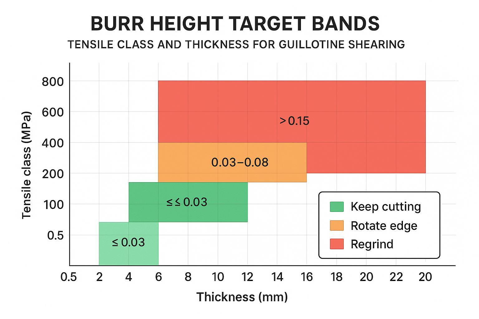
A burr height threshold for shearing only works if it’s tied to an action. Use bands so different shifts don’t make different decisions on the same edge.
Example internal acceptance criteria (not an international standard)
Below is an example of internal burr-height limits used in production control. The measurement criteria in the tables below reflect the blade condition thresholds Maxtor Metal references when evaluating shear blade performance during field reviews. Validate and adjust against your OEM guidance, customer requirements, and your own process capability.
(A) Low-carbon steel (≤350 MPa)
| Sheet thickness | Green (keep running) | Amber (rotate next planned stop) | Red (rotate now; if persists after verified clearance → regrind) |
|---|---|---|---|
| 0.8–2 mm | ≤0.05 mm | 0.05–0.10 mm | >0.10 mm |
| 2–6 mm | ≤0.08 mm | 0.08–0.15 mm | >0.15 mm |
| 6–12 mm | ≤0.12 mm | 0.12–0.20 mm | >0.20 mm |
(B) High-strength steel (350–700 MPa)
Because of springback and a larger fracture zone, limits are often tightened/shifted.
| Sheet thickness | Green (keep running) | Amber (rotate next planned stop) | Red (rotate now; if persists after verified clearance → regrind) |
|---|---|---|---|
| 1–3 mm | ≤0.07 mm | 0.07–0.12 mm | >0.12 mm |
| 3–8 mm | ≤0.10 mm | 0.10–0.18 mm | >0.18 mm |
| 8–15 mm | ≤0.15 mm | 0.15–0.25 mm | >0.25 mm |
Decision rule
- Green: keep running; log the measurement.
- Amber: rotate at the next planned stop.
- Red: rotate now; if red persists after verified clearance, trigger regrind.
Measurement method (make the data defensible)
- Tooling: a burr gauge or a toolmaker microscope (e.g., 50×), with a defined reading rule.
- Sampling: measure left/center/right, 3 points each (9 readings total); record max, average, and standard deviation.
- Minimum resolution: use an instrument with resolution at least 0,01mm (preferably finer).
- Repeatability: if multiple shifts measure, run a simple check to confirm different operators obtain comparable readings.
Edge chamfer/hone and visual cues
Burr is not only a clearance problem. A sharp blade with poor gap can burr—but a dull blade with perfect gap can burr too.
Use visual cues that are easy to standardize:
- Reflective bright line along the edge: rounded bevel (edge no longer a crisp line).
- Micro-chipping: repeating burr “spikes” along the cut length.
- Double cut/step: frequently correlates with clearance too tight (verify before regrind).
Sampling and measurement method
If you want burr data you can defend, standardize sampling and the measuring tool.
Sampling cadence (simple default)
- Once per shift per active shear, and once immediately after any clearance change or rotation.
Cần ghi lại những gì
- Material family + thickness
- Clearance target and measured left/center/right
- Burr height (max observed) + method
- Operator/shift and action taken
Avoid “looks OK.” If you don’t have a dedicated burr gauge, use a consistent comparator method until you do.
Lịch trình đảo lưỡi dao và nhật ký vận hành
Edge-use sequence (four sides)
A 4-edge blade only pays off if your rotation order is standardized.

Recommended rule: rotate in a fixed sequence (Edge 1 → 2 → 3 → 4). If you skip an edge due to a nick, document it and why. A fixed rotation order prevents accidental reuse of a degraded edge and makes the log unambiguous—if you always rotate 1→2→3→4, any out-of-sequence entry is immediately visible as an anomaly.
Rotation “done when…”
- Clearance verified left/center/right
- One controlled test cut inspected
- Log updated (edge number, date, cut count estimate)
Shift-level inspection cadence
A practical cadence for mixed steels:
- Start of shift / job change: quick edge visual check + verify the last recorded clearance basis matches the job.
- During production: burr sample at the defined interval; record any change in cut sound as a note.
- End of shift: decision logged (keep / rotate / pull for regrind).
Rotation record template essentials
Your rotation record is the backbone of traceability—and the easiest place for gaps to hide.
Minimum fields (audit-ready)
- Blade set ID, machine ID
- Edge number in use (1–4)
- Material mix (thickness range + tensile class)
- Clearance target + measured left/center/right
- Burr height + measurement method
- Decision and sign-off
Two fields that make the log useful for cost and planning:
- Estimated cut count or runtime
- Regrind count
That set of fields is enough to be a reversible shear blade rotation log that quality and maintenance can both use.
Tiêu chuẩn mài lại và kiểm soát quy trình mài
Triggers and minimum removal
Regrind is a controlled response to sustained indicators—not the first reaction.
Trigger regrind when BOTH are true
- Burr stays in your red band, and
- Khe hở đã được xác minh (trái/giữa/phải) và hiệu chỉnh, nhưng bavia vẫn vượt quá giới hạn.
Đồng thời kích hoạt quy trình mài lại (hoặc thay thế) khi có vết mẻ, nứt hoặc nếu lưỡi dao đã đạt đến kích thước tối thiểu của OEM. Khi vết mẻ là nguyên nhân kích hoạt, dạng phá hủy — mỏi so với va đập — sẽ quyết định hành động khắc phục là điều chỉnh khe hở hay thay đổi độ cứng và mác thép. Việc xác định sai dạng phá hủy sẽ dẫn đến tình trạng mẻ lặp lại sau chu kỳ mài lại tiếp theo. Shear Blade Edge Chipping Root Cause Analysis: Fractography and Decision Tree cung cấp phương pháp đọc thực tế tại xưởng và các hiệu chỉnh SOP tương ứng.
Về lượng mài tối thiểu: chỉ mài bỏ lượng cần thiết để khôi phục cạnh cắt liên tục và góc vát chính xác. Các lượt mài sâu sẽ làm giảm tổng tuổi thọ.
Bảo toàn biên dạng hình học và dung sai
Tiêu chuẩn mài lại lưỡi dao xén của bạn trước hết phải bảo vệ biên dạng hình học—bởi vì sự sai lệch hình học sẽ buộc phải thay đổi khe hở, và thay đổi khe hở sẽ dẫn đến bavia.
Theo các thuật ngữ kỹ thuật khách quan (và nhất quán với cách Maxtor Metal tiếp cận công việc mài chính xác):
- Theo dõi kích thước tối thiểu của OEM và dung sai cho phép như các giới hạn được kiểm soát.
- Kiểm soát nhiệt độ mài; vết cháy nhiệt/đổi màu là dấu hiệu phế phẩm.
- Xác minh độ thẳng và độ đồng đều của chiều dày trên toàn bộ chiều dài.
- Đánh bóng nhẹ/làm sạch bavia sau khi mài để tránh tạo ra bavia giòn dễ gãy rụng vào sản phẩm.
Các điểm kiểm tra sau khi mài cần tiêu chuẩn hóa:
- Không có vết cháy nhiệt trên cạnh cắt
- Độ thẳng/độ phẳng đã được xác minh (phương pháp dùng thước thẳng hoặc đồng hồ so)
- Chiều dày được kiểm tra tại nhiều điểm (bằng panme)
Thực tiễn ngành đối với dung sai kích thước sau khi mài thường hướng tới độ song song của chiều dày trong khoảng 0.05 mm từ đầu này đến đầu kia và độ biến thiên chiều dày ≤0.025 mm trên mỗi 300 mm chiều dài lưỡi dao—hãy xác nhận lại với các giới hạn quy định của OEM. Quy trình kiểm tra sau khi mài của Maxtor Metal bao gồm xác minh vết cháy nhiệt, đo độ thẳng toàn bộ chiều dài và lập bản đồ chiều dày bằng panme tại năm vị trí trước khi bất kỳ lưỡi dao mài lại nào được xuất xưởng. Nếu khoảng thời gian giữa các lần mài lại vẫn ngắn mặc dù đã kiểm soát biên dạng hình học một cách nghiêm ngặt, mác thép của lưỡi dao có thể là yếu tố hạn chế — cấu trúc vi mô carbide và khung lựa chọn dạng phá hủy giữa D2 và SKD11 được đề cập trong D2 vs SKD11 tool steel selection guide for shearing blades.
Đối với các hoạt động sản xuất mà tần suất mài lại là yếu tố chi phí chính—đặc biệt là trên thép cường độ cao AHSS hoặc vật liệu có lớp phủ—việc chuyển sang kết cấu lưỡi dao ghép hợp kim có thể kéo dài đáng kể tuổi thọ cạnh cắt giữa các lần mài lại. Mô hình chi phí trên mỗi mét đầy đủ và dữ liệu thử nghiệm thực tế có sẵn trong Tungsten Carbide Inlaid Shear Blades ROI Guide for AHSS.
Kiểm tra lắp đặt sau khi mài
Sau khi lắp đặt lại bộ dao đã mài:
- Vệ sinh bệ gá, siết lực theo thông số kỹ thuật, xác minh khe hở trái/giữa/phải.
- Chạy thử nghiệm cắt và đo bavia.
- Ghi lại thông số cơ sở để ca làm việc tiếp theo không phải phỏng đoán.
Để biết phương pháp tính toán độ dày căn đệm đầy đủ sau khi mài lại, vui lòng xem regrinding thickness reduction compensation and shim stack guide.
Tải lượng motor như một tín hiệu đối chiếu

Thiết lập biên đồ dòng điện cơ sở
Tải/dòng điện của động cơ sẽ không thay thế việc kiểm tra bavia hoặc khe hở, nhưng nó có thể chứng minh cho sự gia tăng lực cản cắt.
Bắt đầu với một thông số cơ sở:
- Sử dụng các số đọc từ VFD/bộ biến tần hoặc các cảm biến được lắp đặt.
- Thiết lập thông số cơ sở theo nhóm vật liệu và dải chiều dày.
- Theo dõi xu hướng qua nhiều tuần, không chỉ trong một ngày.
Các Tài liệu ReliaMag về việc thiết lập thông số cơ sở và theo dõi xu hướng dòng điện động cơ chỉ ra sai lầm cốt lõi: nếu không có thông số cơ sở, xu hướng và ngưỡng, dữ liệu dòng điện chỉ là nhiễu.
Dải cảnh báo và giám sát an toàn
Thiết lập các dải cảnh báo tương ứng với thông số cơ sở của riêng bạn và xác thực chúng trên các lượt chạy thử đạt tiêu chuẩn.
Nếu bạn sử dụng máy biến dòng, hãy tuân thủ các quy tắc an toàn CT: Hướng dẫn của NK Technologies về giám sát dòng điện để bảo trì dự đoán lưu ý rằng cuộn thứ cấp của CT không được để hở mạch khi có điện.
Mối tương quan với bavia và khe hở
Sử dụng dòng điện như một bước kiểm tra chéo:
- Dòng điện tăng + bavia tăng + độ lệch khe hở đã xác minh → khắc phục thiết lập trước.
- Dòng điện tăng + bavia ổn định → kiểm tra cơ cấu kẹp giữ, căn chỉnh, bôi trơn hoặc lực cản cơ học.
- Dòng điện ổn định + bavia tăng → có khả năng do biên dạng cạnh cắt/độ cùn dao.
Hồ sơ tài liệu và tuân thủ quy chuẩn
Kiểm soát phiên bản, phạm vi áp dụng và lưu ý an toàn
Kiểm soát tài liệu
- Tiêu đề SOP / Hướng dẫn công việc: Lịch trình xoay lưỡi dao đảo chiều 4 cạnh và tiêu chuẩn mài lại
- Chủ sở hữu tài liệu: Bảo trì / Chất lượng
- Phiên bản: v1.0
- Ngày có hiệu lực: 2026-07-02
- Tần suất xem xét: hàng quý (hoặc sau bất kỳ sửa đổi nào của OEM/sách hướng dẫn)
Nhật ký sửa đổi (mẫu)
| Phiên bản | Ngày | Người thay đổi | Summary of change |
|---|---|---|---|
| v1.0 | 2026-07-02 | Initial release |
Scope & applicability
This protocol is a best-practice framework for guillotine shears using reversible multi-edge (4-edge) blades on 0.5–20 mm carbon, stainless, and high-strength steels.
Safety & responsibility disclaimer
- This document does not replace your machine OEM manual, lockout/tagout procedures, or site EHS requirements.
- OEM limits and instructions always take precedence (minimum dimensions, allowable straightness/flatness, torque, blade gap/clearance range, and inspection intervals).
- Blade handling and clearance adjustments should be performed only by trained/qualified personnel with appropriate PPE and guarding in place.
- If there is any conflict between this protocol and an OEM manual, follow the OEM manual and record the deviation in the log.
Rotation and regrind traceability
Minimum traceability pack per blade set:
- Blade ID and spec (where available)
- Rotation log (edge usage history)
- Regrind log (date, key checks, pass/fail)
- Nonconformance notes (what happened, what was corrected)
OEM-dependent limits and audits
Write into the SOP that OEM limits win:
- Minimum blade dimensions after regrinds
- Straightness/flatness limits
- Hole/seat wear limits
Attach OEM charts/manual pages as controlled documents (with revision) if your quality system requires it.
Training and continuous improvement
Train for consistency:
- clearance measurement left/center/right
- double-cut vs tearing identification
- burr measurement and recording
- rotate vs regrind decision logic
Then review logs monthly to adjust burr bands to your downstream requirements—not to opinion.
Tài liệu tham khảo và cẩm nang hướng dẫn (chọn lọc)
The following publicly available resources support the maintenance philosophy in this article (multi-edge rotation, resetting blade gap after turning/sharpening, and controlling regrind tolerances). Always verify applicability to your specific shear model.
- Tennsmith LM/MSE Series Operation & Maintenance Manual — four-edge blades, factory-set clearance example, and the requirement to reset clearance after turning to a new edge or after re-sharpening: https://www.trick-tools.com/common/documentation/mse1016-manual.pdf
- Genesis GXP Mobile Shear manual excerpt (demolition/mobile shear context; useful for multi-edge rotation mindset and inspection intervals such as 40–80 hours rotation guidance Và rotation when edge radius reaches 1/8 in (3 mm)): https://www.andersonequip.com/web/files/MfrModelDocs/GEM-GXP-broc.pdf
Nghiên cứu tình huống (ví dụ thực tế)
The following case example is drawn from a maintenance review conducted with a Maxtor Metal D2 shear blade customer. Customer identity anonymized per standard disclosure practice.
Context
- Factory: automotive parts stamping center (anonymous)
- Machine: 3200 mm hydraulic guillotine shear
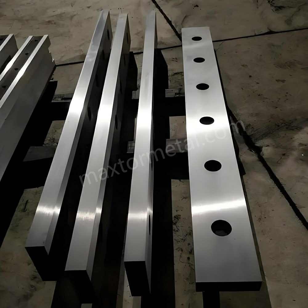
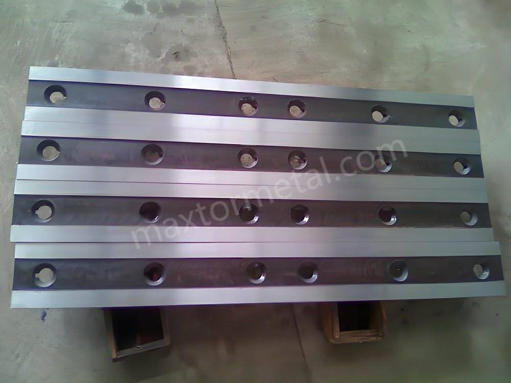
- Blade: 4-edge reversible D2 shear blades (vacuum heat-treated, 3200 mm, supplied by Maxtor Metal)
- Material: ASTM A36, 4 mm
- Operation: two shifts/year-round
Results represent a single documented maintenance trial; outcomes may vary by machine type, material grade, and operating conditions.
Before (no standardized rotation schedule)
- Rotation triggered inconsistently when burr “looked bad”
- Uneven utilization across edges (Edge 1 over-used; Edge 2 nearly new; Edge 3/4 inconsistent)
- No rotation log
After (measurement-based schedule + rotation log)
Inspection every 120–150 operating hours (interval established from baseline wear data collected during the first two months of the trial; adjust to your actual wear curve and OEM guidance), recording:
- Edge No.
- Operating hours
- Burr height
- Edge radius
- Người điều hành
Rotate when any of the following occurs:
- Burr > 0.10 mm
- Edge radius ≈ 0.20–0.30 mm
- Cut sound changes noticeably
- Burnished zone increases visibly
Measurement sequence for the first piece each shift:
- Tooling: 50× toolmaker microscope + burr gauge
- Method: left/center/right, 3 points each (9 readings total); record max/avg/std dev; trend for 3 shifts
Kết quả
| Hệ mét | Trước | After (4-month average) |
|---|---|---|
| Max burr | 0.18 mm | 0.09 mm |
| Average burr | 0.11 mm | 0.05 mm |
| Unplanned blade changes | 5 / month | 2 / month |
| Blade removals/installs | 9 / month | 6 / month |
| Scrap rate | 2.3% | 1.1% |
| OEE | 82.4% | 85.6% |
Ghi chú: The burr-height thresholds and rotation intervals shown above represent an example of an internal production standard for a 4 mm low-carbon steel application. Actual acceptance limits should be validated against the machine OEM recommendations, customer quality requirements, material grade, and sheet thickness.
Kết luận
A 4-edge reversible blade gives you four chances to stay ahead of burr and downtime—if you manage it like a controlled process.
Tie actions to quantified thresholds: verify clearance, measure burr, rotate to the next edge first, and regrind only when limits persist across a verified setup. Done well, this stabilizes cut quality, extends rotation and regrind intervals, lowers TCO, and protects OEE.
That’s why Maxtor Metal includes rotation log templates and regrind criteria checklists in its blade maintenance documentation—the measurement discipline is built into the delivery, not left to be reconstructed at the machine.
If you want a reference point for the blade type discussed here, see the Maxtor Metal precision shear blades for guillotine applications for tooling specifications and contact options.
FAQs:
CH: Độ hở ban đầu phù hợp cho lưỡi dao cắt tôn thủy lực (máy cắt guillotine) là bao nhiêu?
A common baseline is around 7% of material thickness, then adjust for material strength and actual edge results. The Shear Fundamentals training note explains both the baseline and the failure modes.
CH: Làm thế nào để phân biệt ba-via do khe hở cắt sai hay do lưỡi dao bị cùn?
TL: Trước tiên hãy kiểm tra khe hở cắt tại 3 vị trí: trái, giữa và phải. Nếu sau khi điều chỉnh chính xác mà ba-via vẫn lớn, hãy nghĩ đến kết cấu hình học của cạnh dao (vát cạnh bị vê tròn, mẻ vi mô). Hiện tượng "mặt cắt đôi/tạo bậc" chứng tỏ khe hở quá hẹp; ngược lại, vết xé và ba-via dày thường là do khe hở quá rộng.
CH: Khi nào tôi nên đảo mặt lưỡi dao cắt lật 4 cạnh?
TL: Hãy đảo mặt dao khi kích thước ba-via chạm đến "vạch vàng cảnh báo" (hoặc khi cạnh dao có dấu hiệu vê tròn sớm) để có thể xử lý trong ca dừng máy chủ động theo kế hoạch. Việc đảo cạnh dao tiết kiệm chi phí hơn nhiều so với mài lại và giúp bảo vệ chỉ số hiệu suất thiết bị tổng thể (OEE).
CH: Khi nào tôi nên mang dao đi mài lại thay vì chỉ đảo mặt cạnh dao?
TL: Hãy mài lại khi ba-via vẫn vượt quá mức cho phép sau khi đã (1) đảo sang cạnh dao mới và (2) kiểm tra kỹ khe hở cắt cũng như độ song song. Ngoài ra, cần mài lại hoặc thay thế nếu dao bị mẻ, nứt, hoặc khi kích thước dao đã chạm đến hạn mức tối thiểu do nhà sản xuất thiết bị gốc (OEM) quy định.
CH: Nhật ký đảo mặt dao cắt cần bao gồm những gì để sẵn sàng đáp ứng kiểm toán?
TL: Mã định danh dao (Blade ID), mã máy, số hiệu cạnh cắt, nhóm/độ dày vật liệu, khe hở cắt mục tiêu + số đo thực tế trái/giữa/phải, chiều cao ba-via + phương pháp đo, biện pháp đã xử lý và ký xác nhận. Hãy bổ sung thêm số lần cắt/thời gian vận hành và số lần mài lại để phục vụ phân tích TCO.
CH: Việc giám sát dòng điện động cơ có thể thay thế hoàn toàn việc kiểm tra ba-via và khe hở cắt không?
TL: Không. Dòng điện chỉ là tín hiệu bổ trợ và chỉ báo xu hướng. Nó có thể cảnh báo sớm lực cản cắt đang tăng lên, nhưng không thể chẩn đoán chính xác lỗi do hiện tượng trượt khe hở hay do kết cấu hình học cạnh dao nếu không tiến hành kiểm tra vật lý trực tiếp.
Tác giả
Jesse Xu — Senior Quality Engineer, QA (Quality Assurance), Maxtor Metal
- Experience: 15 years in industrial blade quality assurance and failure analysis
- Focus: diagnosing edge chipping and abnormal wear; distinguishing heat-treatment issues vs. material segregation
- Certifications: ASQ-CQE, ISO 9001 Lead Auditor, ASNT Level II

 English
  Spanish
  Italian
  French
  Portuguese
  Russian
  German
  Arabic
  Hindi
Hindi  Vietnamese
  Indonesian
  Japanese
  Korean