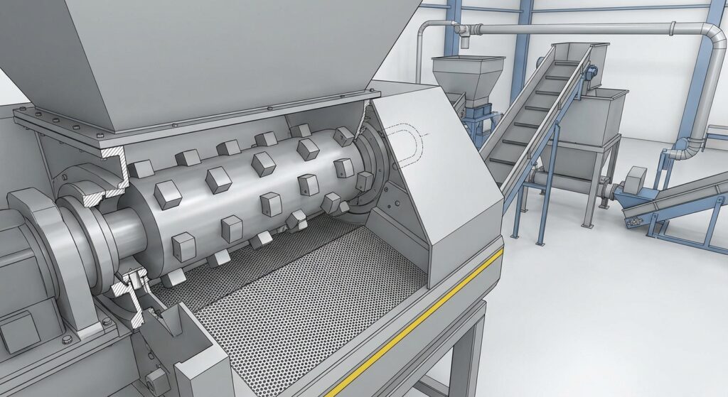
In abrasive plastic streams—glass-filled regrind, mineral-filled compounds, or bales that carry sand and grit—blade wear is rarely “just a materials problem.” In a single-shaft shredder, setup choices decide whether knives stay in steady cutting or spend their life heating, rubbing, and reverse-cycling.
You control more levers than most plants document: feed rate uniformity, the speed/torque regime, and how the screen and cutting gap force material to re-circulate in the cutting chamber.
Knife engineering still matters—steel choice, heat treatment quality, coatings, and edge geometry are the last line of defense for abrasive plastic recycling blades—but it works best when the process isn’t fighting the knives.
Finally, the most reliable maintenance trigger isn’t “it feels dull.” Track kWh/ton, vibration trend, and reverse cycles. Those signals show wear well before you reach the point of chipped corners, cracked edges, or a jam that takes the line down.
Principaux points à retenir: Stabilize feed before touching RPM. Run the lowest speed that still cuts cleanly at your target throughput. Keep the cutting gap tight and verified, and use kWh/ton + reverse cycles to time sharpening.
Introduction
Abrasive plastics don’t fail blades in one dramatic moment—they grind them down by forcing more sliding contact, more heat, and more recirculation inside the chamber. When that happens, you see the same pattern: rising motor load, more reverse cycles, hotter cutting edges, and eventually micro-chipping or rolled edges.
That’s why setup decisions typically drive blade life and uptime more than the steel grade alone. If your feed surges, or your screen is too tight for the material condition, the shredder will “work” but it will do it by rubbing and reversing—both of which accelerate edge wear.
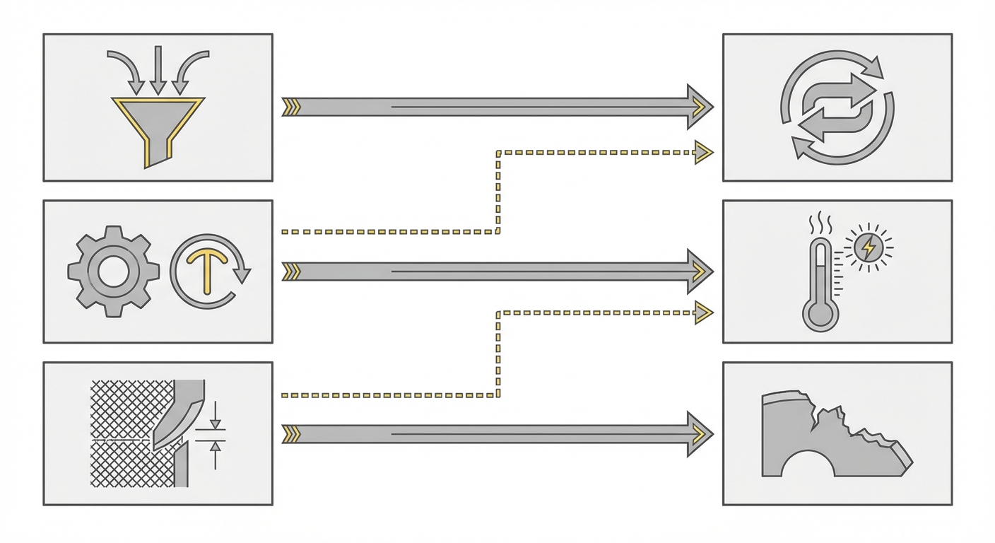
The controllable levers are straightforward:
- Feed rate (and how uniform it is)
- Rotor speed/torque (the regime you operate in)
- Screen and cutting gap (how hard you force size reduction per pass)
Engineering the knives closes the loop: steel family, heat treatment, coatings/hardfacing, and edge geometry for abrasive plastic recycling blades. Those choices determine how much abuse the edge can take before it chips, rounds, or loses bite.
On the monitoring side, don’t wait for catastrophic symptoms. Use kWh/ton, vibration/noise trend, and reverse cycles as measurable triggers to schedule maintenance before failures.
Process setup
Feed rate control
Abrasive feedstock punishes inconsistency. A steady, metered feed keeps the rotor in a predictable cutting mode; surges push the machine into overload behavior (high current/torque spikes, reverses, and heat).
Control points that usually pay back fastest:
- Prevent surges: avoid “dump feeding” where a slug of material hits the rotor, then the chamber runs half-empty.
- Meter the feed: a controlled conveyor/ram reduces jams and dulling; a 2025 technical note emphasizes that overfeeding increases jams and accelerates dulling/overload events in plastics processing (matching rotor speed, screen size, and knife gap (2025)).
- Treat contamination as a process variable: if bales carry grit or fines, upstream screening and wash steps reduce abrasive load before it hits the knives.
What failure looks like when feed rate isn’t controlled: more reverse cycles per hour, “spiky” motor current, and knives that come off the rotor with polished, rounded edges rather than a clean wear land.
Rotor speed and torque
For abrasive plastics, faster isn’t automatically better. Higher RPM can increase sliding contact and heat if the screen and gap force the material to circulate. A slower, higher-torque regime often reduces edge temperature and helps the knives “bite” rather than rub—provided feed is stable.
Practical decision logic:
- If you see frequent reverses, first reduce peak loading (feed surges) before changing RPM.
- If the machine cuts cleanly but kWh/ton rises over time, check whether you’re in a high-RPM “rubbing” regime created by a restrictive screen/gap.
- Match speed to your discharge requirement: MAXTOR METAL notes that slow rotor speed pairs better with smaller screen openings, while higher speed typically needs larger openings to avoid excessive recirculation and heat (as discussed in MAXTOR METAL’s 2025 note on matching rotor speed, screen size, and knife gap).
What failure looks like when RPM/torque regime is wrong: hotter cutting chamber, smeared/softened plastic buildup, and edges that “lose bite” quickly even when the steel is sound.
Screen and cutting gap
Screen and gap settings decide how hard you’re forcing size reduction per pass—and how long material stays in the cutting chamber. In abrasive plastics, too-restrictive settings can turn cutting into grinding.
Safety note: Before you change screens, adjust the cutting gap, or enter the cutting chamber, follow your site’s lockout/tagout procedure, confirm the rotor can’t move, and use the shredder OEM’s service instructions. Mechanical work on rotating equipment should only be done by trained personnel. For baseline safety requirements, see OSHA’s The Control of Hazardous Energy Lockout Tagout OSHA Standard 29 CFR 1910.147, and the risk-control principles in ISO 12100 Safety of Machinery General Principles for Design Risk Assessment and Risk Reduction et ISO 14118 Safety of Machinery Prevention of Unexpected Start-up (Europe: EN 1037). Key setup principles:
- Screen size is a wear lever: smaller openings improve size control, but they increase residence time and abrasive contact.
- Cutting gap is a wear multiplier: a tight, verified gap supports clean shearing; a gap that opens up unevenly can increase rubbing, noise, and vibration.
- Verify gap uniformly across the full knife length. One “wide corner” is enough to start uneven loading and edge chipping.
Practical boundary conditions (keep it safe and reproducible):
- Use OEM definitions for “gap”: document where you measure (e.g., near both ends + the middle) and how you lock the rotor before measuring.
- Uniformity matters more than the absolute number: a slightly-off nominal gap that’s consistent end-to-end often cuts more predictably than a “perfect” nominal gap with one wide spot.
- Treat any change as a new baseline: after you change the screen, gap, or knife set, expect kWh/ton and reverses/hour to shift—then re-establish your baseline rather than comparing to last month’s numbers.
A useful rule for troubleshooting is sequencing: if you need fewer reverses and less heat, fix feed uniformity first, then set a reasonable RPM/torque regime, then adjust screen and gap to hit size.
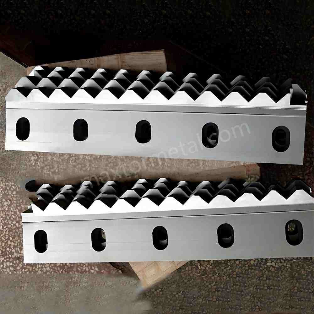
Blade engineering (abrasive plastic recycling blades)
Steel and hardness targets
In abrasive plastic recycling blades, you’re always balancing two failure modes:
- Abrasive wear (edge rounds over; kWh/ton rises; cut quality drifts)
- Impact-driven chipping (corners break; vibration spikes; sudden jams)
That tradeoff is why “hardest possible” isn’t a universal answer. Contaminated streams and tramp metal demand toughness; glass-filled regrind demands wear resistance.
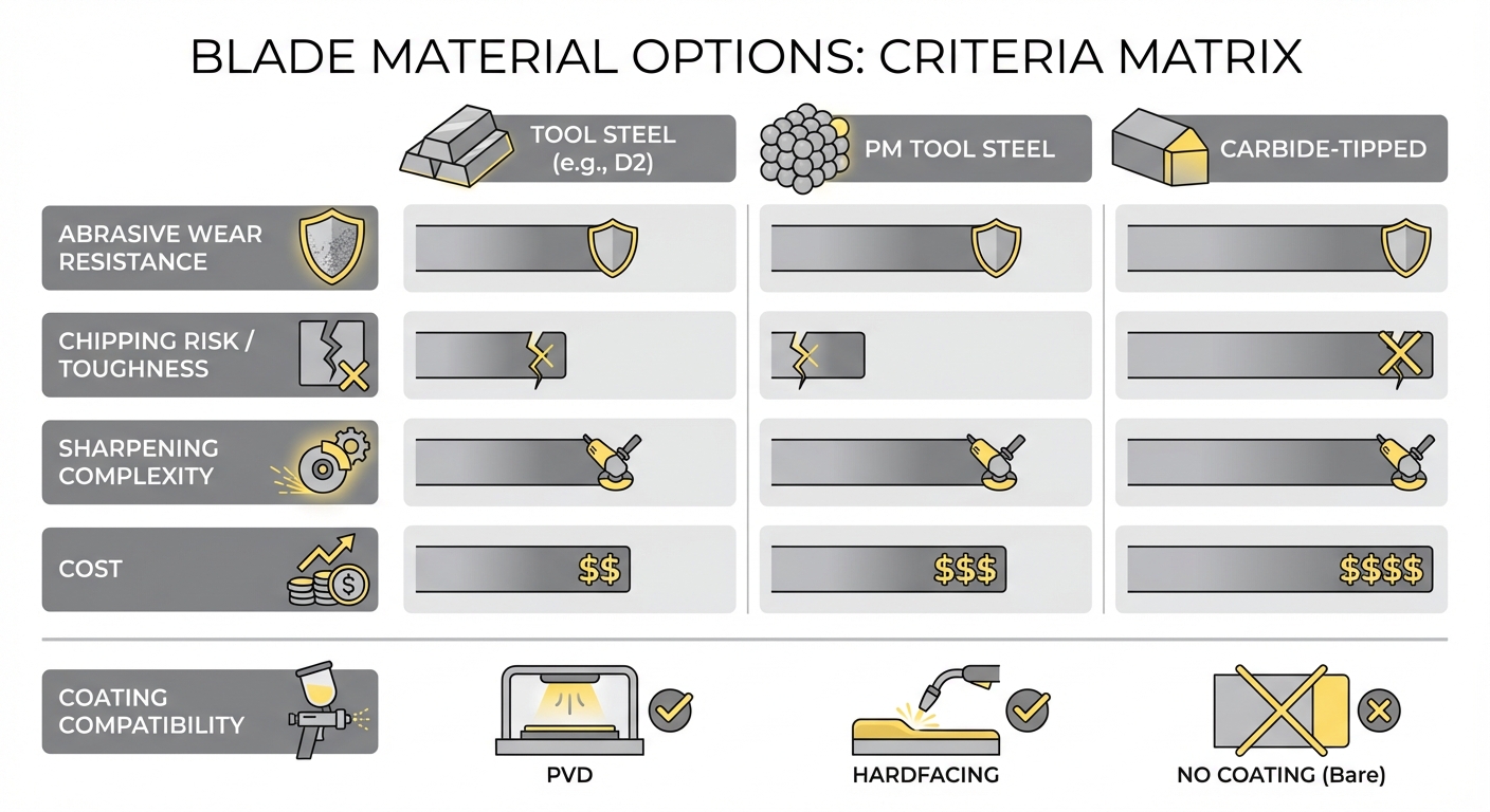
A practical selection approach:
- Start from your dominant damage mode (rounding vs chipping).
- Specify the steel family and the target hardness range appropriate to your machine’s cutting geometry and the expected contamination level.
- Require documentation that makes hardness repeatable across batches.
When you’re sourcing knives, this is also where supplier QA matters. For example, MAXTOR METAL lists incoming material certification and multi-stage inspection (first-article, in-process, final) on its single-shaft shredder fixed blade material options and QC steps. In abrasive service, that kind of traceability reduces the risk of “mystery batches” that chip early or wear unpredictably.
Coatings and hardfacing
Coatings and hardfacing can extend wear life in abrasive plastics—but only when they match the wear mechanism and the sharpening plan.
Use them when:
- You have a stable process window (feed/speed/screen/gap are controlled), and abrasive wear is the dominant limiter.
- You can maintain edge geometry consistently during regrinds (coatings are not magic if the edge is overheated or rounded during sharpening).
Avoid forcing coatings when:
- Your stream includes frequent hard contaminants that cause impact chipping (a very hard surface can fail abruptly if the edge support and toughness aren’t there).
- Your maintenance process can’t preserve the intended edge geometry (coating benefit disappears if you grind it off unpredictably).
Your decision shouldn’t be “coated vs uncoated,” but “what failure mode am I buying time against?”
Edge geometry and sharpening
Edge geometry is the fastest way to change how the knife experiences abrasive plastics. Two edges made of the same steel can wear very differently if one is too thin at the edge or if the included angle drives sliding contact.
Engineering choices that usually reduce chipping without giving up all wear life:
- Micro-chamfer or controlled edge radius to support the edge in contaminated abrasive streams.
- Geometry matched to feedstock: straight vs serrated vs hook/R-shaped edges affect how material is gripped and how load is distributed. For a practical overview of edge styles and where they fit, see MAXTOR METAL’s blade design/edge-style guide (2025).
- Sharpening discipline: keep coolant and avoid overheating; heat damage at the edge can mimic “bad steel” because it accelerates micro-chipping.
Set sharpening triggers based on measured drift, not habit:
- kWh/ton trending up at stable throughput
- reverse cycles increasing at the same feed mix
- cut size distribution widening (more fines + more oversize at once)
Conseil de pro: If you change screen size or gap, reset your “baseline” kWh/ton and reverse cycles. Otherwise you’ll blame the knives for a setup change.
Monitoring and ROI
Condition monitoring signals
Condition monitoring doesn’t need to be complicated. Pick a small set of signals that correlate with wear and damage, then trend them over tonnage.
Signals that typically move first:
- Energy per ton (kWh/ton): rising kWh/ton at the same throughput is a clean indicator of edge rounding, gap drift, or restrictive screening.
- Reverse cycles: more reverses per hour often indicates overload, inconsistent feed, or a screen/gap combination that keeps material circulating.
- Vibration and abnormal noise trend: increasing vibration can indicate uneven knife wear, chipped corners, loose fasteners, or chamber impacts; MAXTOR METAL calls out abnormal vibration/noise and decreased cutting efficiency as maintenance triggers in its maintenance signals checklist (2024).
A quick “wear pattern → signal → likely cause” cross-check:
- Edge rounding / loss of bite → kWh/ton creeps up at stable throughput; cut size distribution drifts → often tied to normal abrasive wear, gap opening over time, or overly restrictive screening.
- Micro-chipping at corners → vibration/noise step-change; sudden reverses/jams → often tied to impact contamination, uneven gap (one wide spot), or an edge geometry that’s too thin for the stream.
- Polished wear land / heat glazing → hotter chamber, smeared buildup, rising reverses → often tied to rubbing mode from high RPM + recirculation, screen plugging, or surge feeding.
Use this as a diagnostic hint, then confirm by inspection—don’t assume one metric tells the whole story.
A simple way to make these signals operational (without over-engineering it):
- Establish a baseline after a fresh grind or knife change: record kWh/ton, reverses/hour, and vibration level for the first stable production run.
- Log at a consistent cadence: per shift (or per batch) is usually enough, as long as you always capture throughput and feed mix notes.
- Use “drift” as the trigger: when kWh/ton and/or reverses/hour stay elevated versus your baseline for a sustained period, schedule an inspection.
- Pair the data with fast checks: verify cutting gap uniformity, inspect screen condition/plugging, and confirm fastener torque.
Example thresholds vary by machine and material, but many plants start by investigating when kWh/ton increases by ~10–20% at the same throughput and feed mix, or when reverses/hour shows a clear step-change over several runs.
Treat these as “time to inspect” signals, not “run to failure” signals.
Data capture notes (so your trends are comparable)
- kWh/ton: total energy (kWh) for a run ÷ tons processed in that same run.
- Tons processed: use one consistent source (belt scale, weighbridge, or accounting tonnage) and don’t mix methods inside the same trend.
- Sampling cadence: per shift or per batch is usually enough; record the same fields every time.
- Reverse cycles: pull the count from the PLC/VFD event log if available (manual operator tallies are often noisy).
- Always log context: feed mix (glass/mineral fill, moisture), screen opening, rotor RPM, and any known contamination events.
If those context fields change materially, treat the new operating condition as a new baseline rather than “blade wear.”
Preventive maintenance windows
A practical PM window is one you can schedule without guessing.
Build it around tonnage and signal drift:
- After a knife change or fresh grind, record baseline kWh/ton, reverses/hour, and vibration level.
- Set an inspection trigger when any one metric drifts materially above baseline (plant-defined threshold) for a sustained period.
- Combine inspection with a fast mechanical verification: cutting gap check, screen inspection, and bolt/fastener torque verification.
What this prevents: the classic cycle where blades are kept in service until they chip badly, then the plant blames “bad steel” when the real root cause was gap drift or feed surges.
TCO metrics and documentation
To prove ROI to procurement and management, document in the same units your plant already uses:
- Blades per 1,000 tons (or knives per 1,000 tons)
- Downtime hours per 1,000 tons attributed to knife changes, jams, or chamber cleanouts
- kWh/ton at stable throughput
- Screen life and screen change labor (if screen wear is a meaningful cost)
Keep the documentation simple:
- Material spec + hardness range + edge geometry drawing
- Heat-treat and inspection records (where available)
- A before/after trend chart for kWh/ton and reverse cycles after a setup or blade change
When you can show that a setup change reduced reverses and lowered kWh/ton, the ROI discussion becomes evidence-based rather than anecdotal.
Conclusion
Lock in stable feed, moderated speed, and a tight cutting gap before upgrading materials. If the process is surge-feeding or forcing constant recirculation through a restrictive screen, even premium steels will wear like commodity knives.
Specify steel, hardness, and edge geometry deliberately; sharpen by tonnage or energy/ton, not by feel. For abrasive plastics, edge support (micro-chamfer/controlled radius) is often what prevents early chipping.
Track vibration, reverse cycles, and blades per 1,000 tons to prove ROI. Once those metrics are stable, material upgrades and coatings become easier to justify because you can measure the delta.
Next step: Put your knife spec in writing—material, hardness range, edge geometry, and required QA documents—so every reorder is repeatable, not a new experiment.
Références
- Occupational Safety and Health Administration (OSHA): The Control of Hazardous Energy (Lockout/Tagout) – OSHA Standard 29 CFR 1910.147
- International Organization for Standardization (ISO): ISO 12100: Safety of Machinery — General Principles for Design — Risk Assessment and Risk Reduction
- International Organization for Standardization (ISO): ISO 14118: Safety of Machinery — Prevention of Unexpected Start-up (Europe: EN 1037)
About the author: Written by Tommy Tang, Senior Sales Engineer (Nanjing METAL Industrial). 12 years in industrial blade applications. Certifications: CSE, CME, Six Sigma Green Belt, PMP. Email: [email protected]
Technical review: Internally reviewed by the MAXTOR METAL engineering/QA team for manufacturing feasibility and common failure modes observed in abrasive plastic service.
Last reviewed: 2026-04-08