

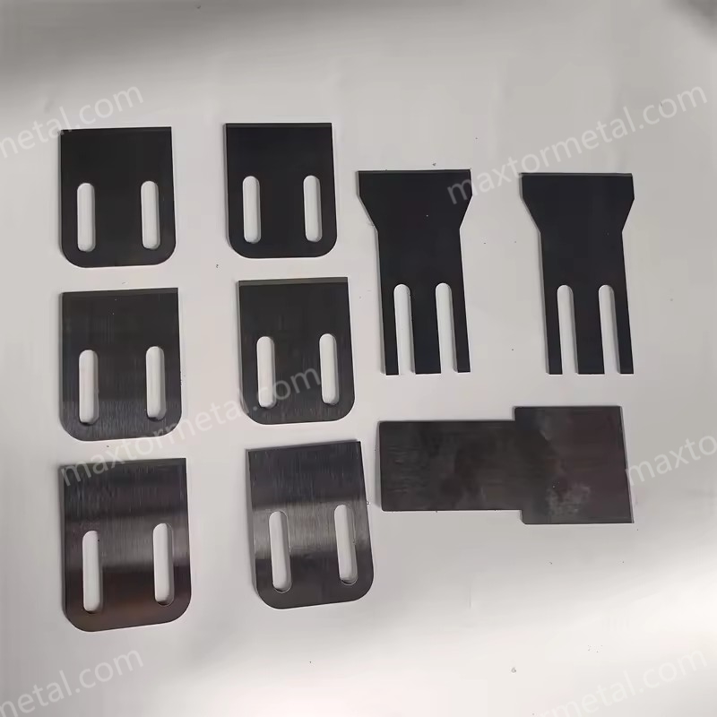
Selecting the right hot face pelletizing blades for air-cooled PE/PP isn’t just about material names on a quote. The right choice directly lowers tails and fines, stabilizes cut quality across shifts, and keeps uptime predictable so your total cost of ownership (TCO) tracks to plan. This guide shows you how to specify blade substrate, hardness, and coating; how to control geometry and tolerances for a clean cut; how to tune air-cooled operation; and how to manage lifecycle and sourcing for consistent, low-variance performance.
Use it three ways:
- Purchasing: build a tighter spec and acceptance checklist.
- Commissioning: align the cutter, validate the gap, and stabilize airflow.
- Maintenance: inspect, regrind, and document so your next order is right the first time.
主なポイント
How this guide was built (scope & verification): This article synthesizes OEM design concepts (alignment/controlled contact), common coated-component QA methods (e.g., XRF thickness checks, calotest thickness validation, and agreed adhesion screening/escalation tests), and shop-floor commissioning practices. Exact tolerances and setup values vary by cutterhead model and resin; treat any “example targets” as internal baselines and confirm final specs with your OEM manual and line trials.
- Prioritize clean, uniform contact at the die face; alignment and stable blade pressure reduce tails/fines fastest.
- Match substrate hardness and coating to resin and filler load; aim for edge toughness on recycled/filled streams.
- Control geometry: consistent edge angle, measured blade-to-die gap, and low runout are the backbone of a clean cut.
- Verify coatings with thickness and adhesion checks (XRF/calotest; scratch/tape as specified) to avoid early failure.
- In air-cooled setups, ensure directed, steady airflow across the die face and cutter path; synchronize cutter speed to haul-off.
- Treat blades as a managed asset: document regrind intervals, inspection results, and QC data to keep TCO predictable.
Selection fundamentals
Match resin and fillers
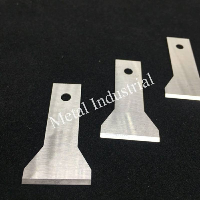
Resin behavior and contamination levels decide how hard and how tough your cutting edge should be. Virgin PE/PP often tolerates sharper edges and higher hardness. Recycled or mineral-filled formulations (CaCO3, talc, glass) drive abrasive wear and chip risk. For those, combine a tough substrate with a hard, low-friction PVD coating so the edge resists micro-chipping and smearing. Practical implication: don’t spec the same blade for washed film regrind and for virgin homopolymer PP; your fines and tails will tell on you.
Blade materials and hardness
Common substrate families include high-speed steels (e.g., M2) and cold-work tool steels (e.g., SKD11/D2). Many suppliers publish typical hardened ranges around the upper 50s to low 60s HRC for these grades, but the right target depends on heat treatment, resin contamination, and the die/cutter design. Higher hardness improves wear resistance, while sufficient core toughness reduces edge chipping during startup or when encountering contaminants. If you run abrasive fillers, pair a tough base with a suitable coating rather than simply pushing hardness higher.
For context on blade alignment and controlled contact principles used by OEM pelletizing systems (the alignment logic is transferable even when the cooling medium differs), see MAAG’s Gala design overview: MAAG Gala pelletizing systems — design principles.
OEM fit and compatibility
Even the best blade fails when the fit is off. Before ordering, verify:
- Hub bolt pattern and hole spacing
- Blade OD/ID, thickness, and clamp features
- Cutterhead model, serial, and any OEM-specific chamfers/reliefs
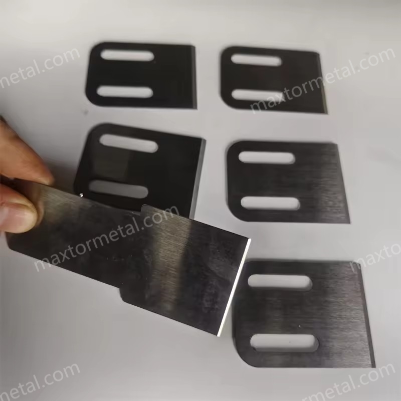
Provide drawings/samples or exact OEM references. Ask the supplier to confirm dimensional tolerances and surface finish on contact faces so the blade seats flat and repeats position across sets. This is the fastest way to avoid vibration, noise, and irregular pellets after changeover.
Geometry and tolerances
Edge angle and micro-hone
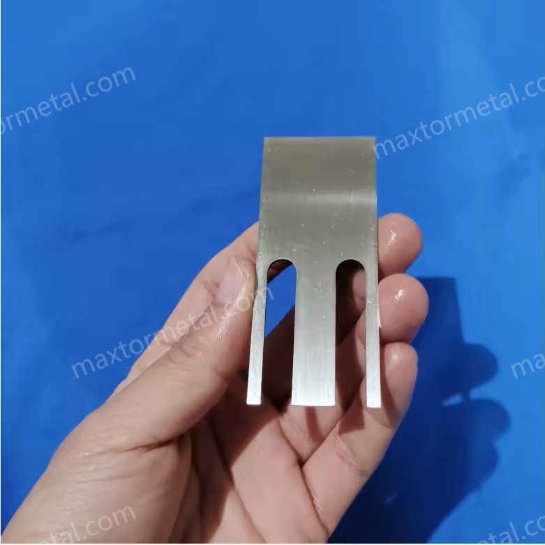
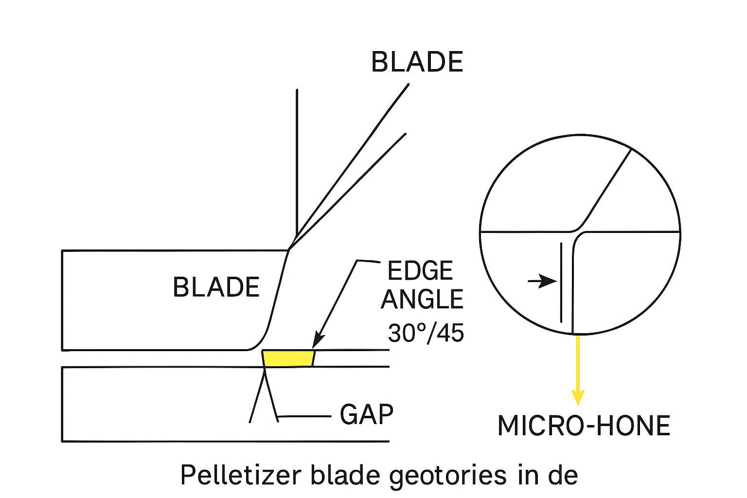
Edge angle sets the tradeoff between sharpness and durability. Market examples in pelletizer applications include 30° and 45° edges; your polymer’s stickiness and die geometry influence where you land. A small, controlled micro-hone (a tiny radius at the very edge) can stabilize the edge and reduce chipping without noticeably increasing fines. Treat the micro-hone as a defined feature, not an accident from hand deburring, and keep it consistent from blade to blade.
For examples of commercially referenced edge angles in pelletizer contexts, see Sollex’s application notes: Sollex pelletizer blade angles and product context.
Blade-to-die gap and alignment
There’s no universal number that works on every die and polymer, so use a commissioning workflow:
- Warm up to steady-state resin temperature and stabilize airflow.
- Establish uniform blade contact using your OEM’s procedure; verify at several clock positions.
- Incrementally adjust the blade-to-die clearance while sampling pellets (sieve for fines, visual for tails/stringers). Move in small, documented steps.
- Re-check after thermal stabilization and again after the first hour. If tails creep up, inspect for runoff, buildup, or chatter.
Why it works: stable, uniform contact and the smallest viable clearance reduce feathering and smear that cause tails. For the alignment logic and pressure control concept, see the OEM discussion referenced above: MAAG Gala cutter alignment concepts.
Flatness, parallelism, runout
Flat, parallel contact and low runout keep the edge tracking the die face evenly. Practical checks:
- Runout: dial indicator on the blade plane as the hub turns slowly; look for minimal variation and address hub wear or contamination if excessive.
- Flatness/parallelism: CMM or optical flat methods on the blade contact face and die face; remove contaminants and burrs.
- Contact pattern: bluing/ink checks during setup can confirm uniform seating.
These measurements prevent “wobble cuts,” intermittent tails, and localized fines. If your OEM publishes model-specific tolerances, follow those.
Example internal targets (verify with your OEM manual): これらは受入検査やトレンド追跡の出発点としてのみ使用してください。目的は、特定のカッターヘッドにおける再現性を確保することです。.
- 刃の平面振れ(組み立て時): 社内目標値(例:「100分の数ミリメートル以下」)を設定し、刃の交換後に基準値と比較して急激な変化がないか調査します。.
- 接触面の平面度/平行度: 社内許容範囲を定義し、毎回同じ方法(同じ治具、同じ測定点、同じ測定器)で測定します。.
- 隙間の均一性: 熱浸透(サーマルソーク)後、複数の時計位置で刃とダイスの隙間が均一であることを確認し、最も状態の悪い位置を記録します。.
刃セットおよびハブごとに結果を記録することで、形状のズレと微粉(ファイン)やテール(ひげ)の発生との相関関係を把握し、プロセスの変動要因を無駄に追跡するのを防ぎます。.
Coatings that work
TiN、TiAlN、CrN、またはDLCの選択
コーティングは刃先の寿命を延ばし、付着を軽減しますが、それは膜厚と密着性が管理されている場合に限られます。選定時に役立つ簡単な比較を以下に示します。
| コーティング | 主な強み | PE/PPにおける代表的な用途 |
|---|---|---|
| 錫 | 高硬度、耐摩耗性、優れた汎用性 | バージン材、低摩擦性がそれほど重要ではない中程度の摩耗環境 |
| TiAlN | 高温硬度および耐酸化性 | より高温での切断、または熱による変色が発生する箇所 |
| CrN | 耐摩耗性と低摩擦のバランス、耐食性 | リサイクル材またはやや粘着性のあるグレード、スメアの抑制に効果的 |
| DLC(a‑C:H系) | 極めて低い摩擦係数、高硬度薄膜 | 粘着性のあるPE/PP、ビルドアップを低減し、刃先の滑りを向上 |
Oerlikon Balzersの品質保証(QA)ガイド(2024–2025年のQA概要)に記載されているように、非破壊膜厚検査用のXRFや、破壊膜厚検証用のカリテスト(calotest)などの検証方法は、コーティングの品質保証において広く使用されています。 コーティング品質保証のための測定技術(Oerlikon Balzers). 簡単な密着性スクリーニングを含む、コーティング部品の一般的な受入ワークフローは、OerlikonのQAガイドにまとめられています。 コーティング部品の品質保証および受入概要(Oerlikon).
MAXTORのようなサプライヤーがコーティングの品質管理(QC)をどのように統合しているか(中立的な例):受入検査において、製造チームはXRFによるPVD膜厚のスポットチェック、熱処理による母材硬度の記録(例:一般的な焼入工具鋼の硬度範囲)、および規定のテープ/スクラッチ法による密着性のスクリーニングを行うことができます。社内プロセス文書やバッチQCの概要は、要望に応じて一般的に共有されます。同ブランドのコーティング付きペレタイザーナイフに関する技術的な入門書については、以下の教育リソースを参照してください。 MAXTOR METAL — PVDコーティングペレタイザーナイフガイド.
コーティングの膜厚と密着性
コーティングの品質保証(QA)は例外ではなく、日常業務として扱ってください。実用的なアプローチは、何を測定するか、どこを測定するか、そして各ロットにどのような書類を添付して出荷するかを定義することです。
- 膜厚:すべてのバッチにおいて、定義された位置でXRFスポットチェックを実施します。定期的なカリテスト(calotest)による検証カットを計画し、必要に応じて顕微鏡写真をアーカイブします。.
- 密着性:注文書(PO)でスクリーニング方法(テープ)とエスカレーション試験(スクラッチ/インデンテーション)について合意し、バッチ/シリアルの追跡可能性を確保して結果を記録します。.
- 記録:ロットごとに、母材グレード、熱処理仕様、測定された硬度範囲、コーティングタイプ、膜厚の平均値/範囲、および密着性試験のメモを記録します。.
受入検査チェックリスト(POまたはIQCフォームにコピー&ペーストしてご使用ください):
- 識別と追跡可能性: 刃セットID/シリアル、ロット番号、コーティングバッチ、日付、検査官。.
- OEM適合性: カッターヘッドのモデル/シリアル、注文に使用された図面の改訂版。.
- 寸法: 外径/内径、厚さ、ボルトパターン/穴ピッチ、皿穴/座ぐり詳細、キー溝/面取り(実測値と許容差を報告)。.
- 接触面の状態: 表面仕上げ要件(指定がある場合)、バリのないエッジ、基準面上でのガタつきがないこと。.
- 組み立て後の形状: ハブ上での刃の平面振れおよび接触パターンの確認(測定方法と測定点を記録)。.
- 母材および熱処理: 鋼種、熱処理証明書(入手可能な場合)、測定された硬度結果+測定位置。.
- コーティング: タイプ、定義された位置でのXRF膜厚測定値(平均/最小/最大を報告)、外観欠陥(ピンホール/剥離)。.
- 密着性: スクリーニング方法(テープ)の結果、仕様で要求される場合はエスカレーション方法(スクラッチ/インデンテーション)。.
- パッケージ: 刃先保護、防錆、取り扱い上の注意。.
これらの手順により、刃先の早期破損を防ぎ、コーティングのばらつきと微粉の発生や運転時間の短縮との相関関係を把握するために必要なデータを得ることができます。.
リサイクルラインへの導入
Micro-case (measurement-first, no guessing): When you trial CrN vs. DLC on the 同じ substrate for recycled PE/PP, set up a simple A/B log so decisions are based on your line’s data.
- Keep constant: resin recipe (filler %, melt index), die plate, cutterhead, airflow setting, and target pellet size.
- Track three KPIs: (1) fines % from the same sieve stack and sampling interval, (2) tails/stringers count per fixed sample mass, (3) runtime hours to first wipe-down and to scheduled regrind.
- Record QC alongside results: XRF thickness readings (mean/min/max), the adhesion screening method used, and the blade set ID.
After one or two stable runs per coating, you’ll usually see whether the limiting factor is abrasion (favoring tougher wear films) or smear/sticking (favoring lower-friction films).
Recycled PE/PP with fines, fillers, or occasional contaminants benefits from lower-friction films (CrN or DLC families) to reduce smear and sticking. Start with a tough substrate + CrN where abrasion dominates; if you still see smear buildup and tailing at steady state, trial DLC on the same substrate and compare runtime between regrinds and sieve-based fines percentage. Document both coating thickness (XRF) and adhesion screening so comparisons are apples-to-apples.
For context on airflow hardware positioning that informs how coatings interact with surface temperature and smear risk (strand pelletizer references; adapt the concepts), see MAAG’s brochures: MAAG PRIMO E — air-knife placement concepts (strand pelletizers).
Air-cooled operations
Strand temperature and airflow
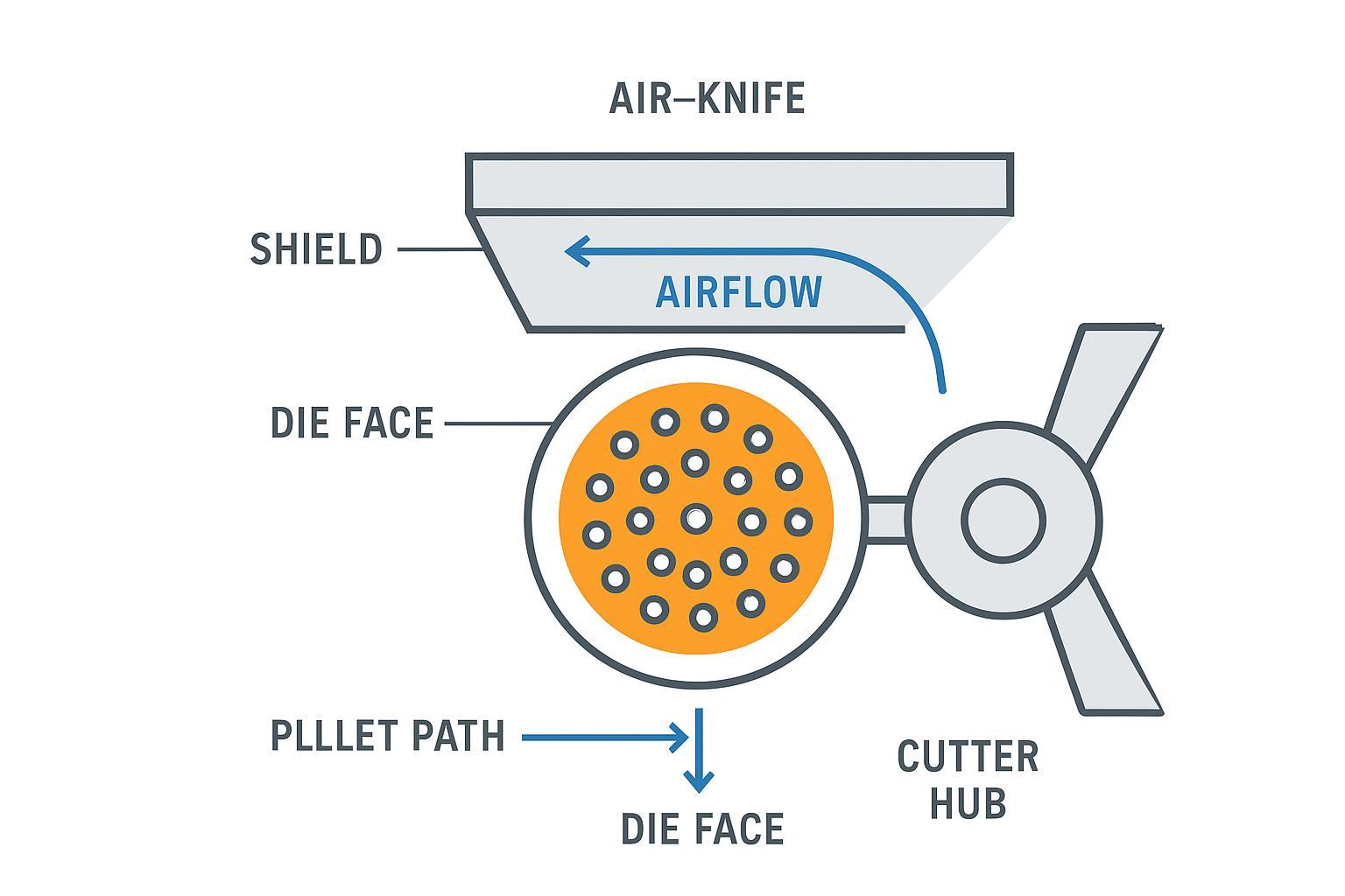
Air assistance should stabilize the polymer surface before the blade arrives, then carry away heat from the cut. Practical signs you’re close: pellets separate cleanly with minimal smear; blade faces stay relatively clean between checks; no visible flutter at the die face. If you see stringers or smeared, comet-tail pellets, increase directed airflow across the die face and verify shielding to prevent turbulence from bouncing back into the cut zone. OEM manuals are the best source for model-specific air-knife positions and recommended ranges.
For a systems view of airflow placement concepts (strand equipment, but the airflow logic is transferable), consult MAAG’s technical brochures: MAAG PRIMO E — airflow placement concepts (strand equipment).
Cutter vs. haul-off sync
Clean cuts depend on synchronized line speed and blade strike frequency. If the cutter is slightly out of sync with haul-off, you’ll see periodic tails or thickness variation. Confirm encoder inputs, check for lag in speed control loops, and tune so the blade meets a stabilized strand at a consistent strike angle and timing.
Startup and changeover checks
- Confirm uniform blade contact and minimal runout after thermal soak.
- Inspect the die face for deposits; clean if any lip buildup is visible.
- Verify directed airflow across the die face and cutter path; adjust hood/knife alignment if flutter is observed.
- Sample pellets at 5 and 15 minutes; sieve for fines and inspect for tails/stringers; adjust clearance in small steps.
- Re-check coating and edge condition after the first hour; wipe away any early smear to prevent buildup.
Lifecycle and TCO
Regrind strategy and limits
Regrind before fines spike. Waiting until the edge is obviously dull increases the risk of tails, over-pressing the blade, and scuffing the die face. Build a trigger from your own KPIs: when sieve-based fines exceed your control limit at steady state or when runtime between wipe-downs shortens materially, schedule a regrind. Keep stock removal minimal and consistent across cycles so geometry stays repeatable. If chipping appears, reassess substrate toughness or micro-hone consistency before blaming coating thickness alone.
Inspection intervals and QC docs
Adopt a simple cadence:
- Shift/daily: Visual check for nicks, burrs, smear; wipe blade face; verify contact and sound.
- Weekly: Inspect runout and fasteners; record pellet sieve data and any tails incidence.
- Lot change or monthly: XRF thickness spot-check on coated blades; adhesion screen as specified; log substrate hardness and any heat-treatment certifications.
Tie these records to blade serials and production lots. Over a quarter, you’ll see which combinations of substrate, coating, and operating window produce the best fines/tails profile on your resin mix.
Sourcing economics and spares
Treat blades as a rotating asset pool. Maintain enough spare sets to cover regrind turnarounds and incoming QC window without jeopardizing uptime. In contracts, specify dimensional tolerances, substrate grade and hardness, coating type, and QA documentation required on each lot. Price is one line item; predictable quality and documented QC are how you avoid paying twice in downtime.
結論
Before you order, specify the substrate and hardness suitable for your resin/filler mix, choose a coating based on wear vs. sticking risk, and define acceptance tests for thickness and adhesion. During commissioning, stabilize airflow, set uniform blade contact, and tune the blade-to-die gap stepwise with pellet feedback to minimize tails and fines in air-cooled PE/PP. Manage regrind timing and QC documentation so your TCO stays predictable and uptime remains high.
If you need a neutral technical reference or to discuss QC practices for coated pelletizer knives, visit the brand homepage: マックストールメタル.
About the team behind this guide: MAXTOR METAL has 15+ years of experience manufacturing custom, precision-ground industrial blades. For pelletizing knife orders, teams typically control repeatability through documented material/heat-treatment records, in-process dimensional checks, and coating QA logs (for example, XRF spot checks for thickness) so users can tie incoming inspection results back to a specific lot.

 English
 Spanish
 Italian
 French
 Portuguese
 Russian
 German
 Arabic
 Hindi
 Vietnamese
 Indonesian
 Japanese
 Korean