薄膜フィルムや不織布を高速でスリッティング(通転)する場合、シアスリッティングは「単なる刃物のセッティング」の域を超え、システム全体の安定性の問題へと変わります。微小な振れ(ランアウト)、不均一な接触、あるいはナイフホルダーの空気予圧(エアプリロード)の変動は、すべて切れ刃の欠陥やライン停止(ダウンタイム)に直結します。
本ガイドは、Maxtor Metalがフィルムおよび不織布のスリッティングラインでのお客様サポートにおいて実践している「現場主義(ショップフロア・アプローチ)」に基づいて執筆されています。すなわち、測定データからベースラインを定義し、計測器で検証し、設定を文書化することで、属人化(一人の作業員の経験則に頼ること)を排除し、異なるオペレーターや交替勤務(シフト)間でも完全に再現可能な製造環境を確立することを目指しています。
For background on circular knife formats and blade families used in slitting, see Maxtor Metal circular knives and blades (linked here only as a reference point for terminology and typical configurations).
- Who this guide helps: managers, maintenance, process engineers
- What spring-loaded, zero-clearance shear slitting solves: it stabilizes the cut point by maintaining controlled contact as conditions change (speed, tension, thermal growth, minor shaft motion).
- Outcomes: cleaner edges, longer life, higher uptime
重要なポイント: In high-speed shear slitting, you don’t “set knives.” You control a system: geometry + rigidity + preload + verification. This is the principle Maxtor Metal’s field team applies across all slitting line commissioning and troubleshooting work.
適用範囲および検証に関する注意事項
The setpoints and “baseline windows” in this guide are intended as practical starting points for experienced operators and maintenance teams.
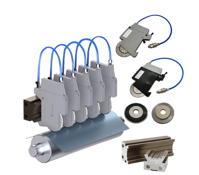
Typical fit (where this guide works best): shear slitting (rotary shear) of thin films and nonwovens on lines using spring-loaded or pneumatic knifeholders, where repeatability at speed depends on controlled overlap/cant/preload and verified runout.
Validate on your line: Knife diameter, holder design (spring vs pneumatic vs hybrid), web structure, speed, tension, temperature growth, and shaft dynamics can shift the stable window. Use short, controlled trials and document results.
If your process differs: crush slitting, score slitting, very low-speed converting, thick/rigid webs, or unusual coatings/adhesives may require different geometry and force strategy—use your OEM guidance as the primary reference.
Safety note: This article is general guidance and does not replace your OEM manual, site-specific LOTO procedures, or EHS requirements.
エンジニアリング原理(設計機構)

Spring-loaded setup only works when the fundamentals are right: stable geometry, controlled overlap and cant angle, and mechanical rigidity.
Shear geometry and cut point stability
Shear slitting is a scissor action between overlapping circular knives. In practice, “clean cutting” depends less on how sharp the knives are and more on whether the cut point stays stable as the line accelerates, warms up, and sees tension variation.
This is where a spring-loaded shear slitting setup earns its keep: it helps maintain consistent contact and loading at the cut point with less operator chasing.
What destabilizes the cut point most often:
- Axial runout (wobble) that modulates overlap every revolution.
- Radial runout that changes effective penetration and creates periodic edge signatures.
- Knifeholder compliance (or inconsistent spring/air preload) that lets contact unload at speed.
A fast way to think about it: if the knife pair is not meeting the web the same way at 0°, 90°, 180°, and 270° of rotation, your edge can’t stay consistent.
Overlap and cant angle baselines
Use baselines as starting points, then tune with a controlled trial cut.
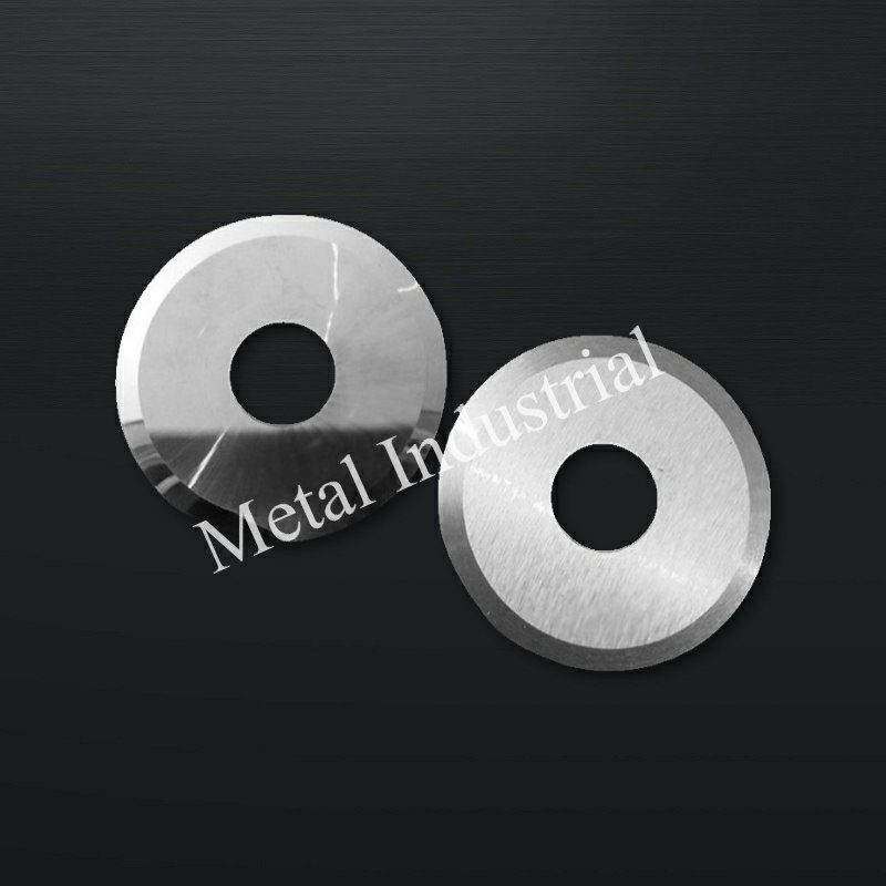
Overlap (intersection depth) baselines for rotary shear slitting overlap setting:
- Thin plastic films: ~0.50–0.75 mm (≈0.020–0.030 in)
- Nonwovens: ~0.75–1.0 mm (≈0.030–0.040 in)
For a full DOE-based treatment of how overlap depth and side clearance interact across substrate types—including Pareto trade-offs between edge quality and knife life—see Optimizing Circular Knife Overlap Depth and Side Clearance.
These ranges reflect the practical starting points Maxtor Metal’s engineering team uses when commissioning new slitting lines or troubleshooting unstable edge quality in film and nonwoven converting projects. If overlap is too low, you’ll see incomplete separation, tearing, or intermittent edge defects. If overlap is too high, you’ll see “plowing,” scalloped edges, excess dust, and accelerated wear.
Quick field signals (overlap too low vs too high):
- Too low: intermittent separation, edge starts to “zipper” at speed, defects worsen with tension variation.
- Too high: rising dust, visible scallop/wave signature, faster heat build-up and polish bands on the knife contact zone.
Cant angle baselines for cant angle shear slitting film setups:
- Plastic film: ~0.25–0.5°
- Nonwovens: ~0.75–1.0°
Maxtor Metal’s field experience across BOPP, PE, and PET slitting projects consistently shows that exceeding 0.5° cant angle on thin films accelerates bevel wear at the nip contact zone—validating the conservative upper bound of this window. If cant angle is too low, the knives tend to rub (heat/dust) and traction at the nip becomes unreliable. If cant angle is too high, the nip becomes overly aggressive and blade wear (and sometimes edge nicking/chipping) increases.
Quick field signals (cant angle too low vs too high):
- Too low: rubbing/heat, adhesive pickup, dust without clean separation.
- Too high: faster wear, edge damage risk increases, and the cut can become “grabby” at the nip.
A useful cross-check is to confirm your setup logic against an established industry slitting reference guide. These references typically summarize the practical relationships among overlap, shear angle, and measurable outcomes—useful for aligning your team on a common starting baseline.
Mounting rigidity and runout targets
If you want a stable zero-clearance shear slitting setup, you need targets that your maintenance team can actually measure.
Practical runout targets (typical baselines):
- Axial TIR (knife face/edge): aim around 0.002 in
- Radial TIR (knife OD): aim around 0.004 in
These numbers come from runout target baselines commonly cited in industry slitting setup references and are useful as a starting point for maintenance. For the bore-fit logic that underpins these targets—including ISO 286 H7/h6 vs H7/g6 selection and assembled TIR verification routines—see Central Bore Tolerance and Runout: Optimizing ISO 286 Fits for High-Speed Slitter Knives.
How to measure (quick method):
- Lock bottom knives to the driven shaft.
- Place a dial indicator on the knife edge (axial) and rotate slowly; repeat on the OD (radial).
For shear slitting, holder bearing condition also matters. A common diagnostic is to confirm the knifeholder bearing does not show excessive radial/axial runout; many industry shear-slitting maintenance guides emphasize the same troubleshooting logic: mechanical condition first, then process adjustments.
キャリブレーション(校正)およびスプリング式ホルダー設定

The goal of spring-loaded knifeholders is to make “contact” a controlled variable, not something that drifts with temperature, minor shaft movement, or operator feel.
Zero-clearance contact and verification
Input: clean arbors/bores/spacers, sharp knives, guarded access, and a runout measurement baseline.
Action:
- Clean and inspect mating surfaces (arbor shaft, spacer faces, knife bores). One trapped chip can become runout.
- Assemble with rigidity in mind: minimize spacer count per pocket; keep the largest spacer nearest the knife where possible.
- Bring knives to zero-clearance contact at the intended cut point using your holder’s adjustment method.
Verify (done when…):
- You can confirm consistent contact around rotation (no “high spot only” contact).
- Your axial/radial runout is within your plant target window before you tune parameters.
If you need a repeatable method for documenting these checks, keep a simple setup sheet that records: knife OD, overlap, cant angle, preload/air pressure, speed, tension, and a quick edge-quality score.
Setting overlap and micro-preload pressure
Zero clearance does not mean “maximum force.” For thin webs, the best setup is usually minimum effective force that keeps the nip stable.
Overlap:
- Start with 0.030–0.040 in overlap for nonwovens and similar compliant webs.
- Start slightly lower for many films, then increase only if separation is unstable.
Micro-preload (airflow/pressure):
- Use the holder’s air assist as a micro-preload, not a clamp.
- A common working window is 20–60 psi at the holder supply (actual force at the knife depends on cylinder area, regulator accuracy, and friction losses).
Quick field signals (preload too low vs too high):
- Too low: contact unloading at speed, lane-to-lane inconsistency, defects increase as speed ramps.
- Too high: unnecessary friction/heat, faster polishing wear bands, and potential web damage (especially on softer structures).
Verify (done when…):
- You can run at target speed without contact unloading (edge defect frequency does not rise with speed).
- Knife wear pattern is even (no localized shiny bands indicating intermittent contact).
Live tuning and documentation
Live tuning is where you turn baselines into a repeatable SOP. The Maxtor Metal field engineering team uses a consistent action sequence to avoid chasing multiple variables at once.
Action sequence (keep it consistent):
- Run a short trial at production speed with your baseline settings locked in.
- Adjust one variable at a time—overlap first, then cant angle, then preload. Never change two simultaneously.
- After each adjustment, re-inspect the edge and log the change before proceeding.
What to log (minimum):
- Overlap setpoint, cant angle, air pressure setpoint, line speed, web tension, and material batch.
- A quick defect code against each trial: fuzzing / feathering / tearing / scallop / dusting.
Verify (done when…):
- Two operators can reproduce the same edge quality on different shifts using the same logged settings without verbal handoff.
Keep the Setup Sheet (see below) filled out for every trial run. Once two consecutive shifts confirm stable edge quality, the current settings become the locked baseline for that material.
SOPチェックリスト(印刷可能バナー)
Pre-start checklist (before bringing knives into contact)
- Verify LOTO/guarding status and controlled access.
- Clean arbor/bores/spacer faces; remove adhesive and trapped chips.
- Confirm spacer stack plan (minimize thin spacers; largest spacer near the knife where possible). For stack-up math and spacer matching discipline that prevents axial shift from compounding across the pack, see Controlling Cumulative Thickness Tolerance in Multi-Knife Slitting.
- Confirm bottom knife lock/drive condition and holder bearing health.
- Measure and record runout baseline (axial/radial TIR).
Trial cut checklist (first 5–10 minutes at production speed)
- Start from baseline overlap/cant/preload; change one variable at a time.
- Inspect edge for feathering, tearing, scallop, and dust bursts.
- Watch for speed-triggered defects (e.g., only above a threshold speed).
- Confirm air supply stability under dynamic load (no droop).
Acceptance checklist (run is “good enough to lock”)
- Edge is stable from start-up to thermal steady state.
- No periodic signature tied to knife circumference/shaft rotation.
- Wear pattern is even across the contact band (no localized polish bands).
- Settings are logged (overlap, cant, preload, speed, tension, material batch).
Shift-change / roll-change checklist (repeatability control)
- Re-check air setpoint and gauge behavior.
- Quick visual inspection for adhesive pickup and dust buildup.
- Spot-check one station for contact consistency (no “high spot only” contact).
- Record any drift and corrective action taken.
Setup Sheet template (copy/paste)
Use a simple one-page record to make results repeatable across operators.
- Date / Shift / Operator:
- Line / Station / Lane ID:
- Material & batch: (film/nonwoven, structure, thickness)
- Knife OD / thickness / bevel details:
- Holder type: (spring / pneumatic / hybrid) and model:
- Overlap setpoint: ____ (in / mm)
- Cant angle setpoint: ____ (deg)
- Preload (air) supply setpoint: ____ (psi / bar)
- Line speed: ____ (m/min)
- Web tension: ____ (N or your unit)
- Runout baseline:
- Axial TIR: ____
- Radial TIR: ____
- Edge quality score (1–5) + defect codes: fuzzing / feathering / tearing / scallop / dusting
- Notes (what changed, one variable at a time):
性能評価および測定指標(メトリクス)
At speed, edge quality is less about a single “perfect” setting and more about whether the system stays inside a stable window.
Track outcomes that connect directly to cost:
- Edge acceptance rate (pass/fail per roll).
- Defect frequency (defects per 1,000 m or per roll).
- 切り替え時間 (minutes to first acceptable roll).
- Knife life (runtime or linear meters per grind/change).
If your edge defects appear with a periodic spacing that matches knife circumference or shaft rotation, treat it as a runout/rigidity clue—not a “material problem.”
Recommended setpoints by substrate
Use these as practical starting points, then validate with your own material and line dynamics.
Maxtor Metal’s recommended starting setpoints by substrate type for spring-loaded zero-clearance shear slitting:
| Substrate | Cant Angle | Overlap | Air Preload (supply) |
|---|---|---|---|
| Thin plastic films (PE/PP/PET, <50 μm) | ~0.25–0.5° | ~0.020–0.030 in (0.50–0.75 mm) | Start low: 20–35 psi; increase only if contact unloads |
| Nonwovens / compliant fibrous webs | ~0.75–1.0° | ~0.030–0.040 in (0.75–1.0 mm) | Mid-window: 35–55 psi to maintain stable nip |
| Laminates / coated webs | Closer to film baseline (~0.25–0.5°) | Tune to minimize dusting; avoid plowing the coating | Start low; coating debris accelerates wear if preload is excessive |
プロのヒント: If you’re forced to increase preload to “stop defects,” pause and re-check runout and spacer stack rigidity first. Preload should compensate for small dynamics, not mask mechanical faults.
Blade materials and coatings selection
Blade life is a wear-mode problem: abrasion, adhesive pickup, heat, corrosion, and micro-chipping don’t respond to the same steel or coating.
Common selection logic (general industry practice):
- Tool steels (e.g., D2): often chosen when you need wear resistance and stable edges in abrasive or filled webs.
- High-speed steels (e.g., M2): often chosen when you need toughness and edge stability under higher thermal load.
- 炭化物: used when abrasion dominates and you can control brittleness risks (alignment, vibration).
For a rigidity-led framework on choosing single, double, or compound bevel geometry before spring-loaded setup begins, see Single, Double, and Compound Bevels for Circular Slitter Knives.
Coatings are usually chosen to shift friction, heat, and adhesion behavior:
- TiN / TiCN / CrN families: used to improve wear and reduce galling in many metalworking and converting contexts.
- DLC: particularly relevant in high-speed spring-loaded shear slitting of thin films, where reduced surface friction at the nip means the minimum effective preload stays lower—less heat, less polish wear, and a wider stable operating window at speed. Maxtor Metal applies DLC on circular shear knives for customers running PE/PP films above 400 m/min where adhesive pickup and friction-driven edge rounding are the primary wear modes.
Long knife life in a spring-loaded setup depends on consistency across shipments, not just initial sharpness. Maxtor Metal maintains lot/heat traceability on all shear slitting blades, with documented hardness verification and dimensional inspection records available per batch. This means when a setup is dialed in and performing well, the next blade order should behave the same way—not require a new round of parameter tuning.
実機導入事例:スプリング式ナイフホルダーが隙間ゼロの安定したシアスリッティングを再現
The following case was handled by Maxtor Metal’s after-sales technical team, led by Jerry Chu, in collaboration with a flexible packaging film manufacturer. It is shared as a real-world troubleshooting example. Customer and site details are anonymized; your exact stable window may differ—validate on your line.
用途
- 材料: BOPP packaging film, 30–40 μm
- Slitting method: pneumatic spring-loaded shear slitting (zero-clearance contact)
- Line speed: 450–650 m/min (defects appeared mainly above ~550 m/min)
- Operating mode: continuous production with 12-hour shifts; multiple top shear holders on a linear rail
- Air supply: approximately 5.5–6.0 bar (observed stable at ~5.8 ±0.05 bar)
Initial symptoms
After about one week of continuous production:
- Intermittent feathered slit edges
- Periodic fine dust bursts
- One slit lane unloading from the bottom knife every 15–20 minutes
- Edge quality changing without recipe modification
Inspection sequence (mechanical first)
- Measure knife runout (dial indicator):
- Bottom knife TIR: 0.008 mm
- Top knife TIR: 0.010 mm
- Both within the team’s acceptable limits
- Check spacer stack: clean faces, no burrs, width consistency OK
- Inspect bearings: rotation smooth; no abnormal play or temperature rise
- Verify pneumatic supply: stable pressure; no leaks found
Root cause
Focus shifted to the spring-loaded knife holder mechanism:
- One holder had noticeably lower manual retraction force than adjacent holders.
- Disassembly found a partially fatigued return spring, 汚染 in the guide mechanism, and inconsistent engagement stroke.
At high speed, the holder occasionally lost constant side-load against the bottom knife. The upper knife momentarily separated and re-engaged, producing periodic feathering, dust bursts, and lane unloading.
Corrective actions
- Replaced the fatigued return spring
- Cleaned and lubricated the guide mechanism
- Reset overlap and rechecked engagement stroke
- Reduced holder air pressure slightly after confirming stable knife contact (to avoid unnecessary friction)
- Verified side-load consistency across all knife holders before restart
Results (two production shifts)
- Feathered edge occurrence: intermittent every 15–20 min → not observed
- Slitting dust: frequent visible bursts → barely noticeable
- Knife unloading events: several per shift → none recorded
- Top knife service interval: baseline → ~15–20% longer before resharpening (primarily from reduced unnecessary friction)
Why lower pressure can extend knife life: once stable contact is maintained, excess pneumatic preload mainly increases sliding friction and heat—accelerating polish wear and edge rounding without improving separation.
Practical lessons learned
- Stable zero-clearance shear slitting depends on consistent side-load, not maximum air pressure.
- If runout, spacers, bearings, and air supply look normal, inspect the holder mechanism (spring condition, guide contamination, engagement stroke).
- A structured order—runout → spacer stack → bearings → pneumatic supply → holder mechanism—reduces wasted blade changes and downtime. For a measurement-first approach to axial and radial TIR diagnosis—including cold-to-hot drift checks—see Axial Runout, Dynamic TIR, and Slit Edge Quality.
- Key calibration steps to standardize SOPs: verify runout/rigidity first, then set zero-clearance contact, set overlap, set micro-preload, and only then tune cant angle and tension with one-variable changes.
- Parameter windows for thin films/nonwovens: films often stabilize around ~0.020–0.030 in overlap and ~0.25–0.5° cant angle, while nonwovens often need ~0.030–0.040 in overlap and ~0.75–1.0° cant angle—then fine-tune for your exact web and speed.
- Next actions: verify runout, log settings, review TCO
If you want to standardize the knife and blade side of that SOP across lines, keep the internal reference for your team here: circular knives and blades for slitting applications.
設置・調整時のトラブルシューティング
Edge defects and corrective levers
One-page decision tree (symptom → checks → levers)
Use this to keep troubleshooting consistent and avoid “turn everything up.”
1) Is the defect periodic (spacing matches knife circumference or shaft rotation)?
- Yes → Treat as mechanical first:
- Check axial/radial runout → spacer stack cleanliness/rigidity → arbor fit → bearing play
- No → Go to process window checks.
2) Does the defect appear only above a speed threshold?
- Yes → Suspect contact unloading / holder compliance / vibration sensitivity:
- Verify preload stability under dynamic load
- Inspect holder mechanism consistency lane-to-lane
- Re-check engagement stroke and side-load behavior
3) Pick the dominant symptom and adjust one variable at a time (after mechanical checks):
- Feathering/fuzzing → overlap slightly up, cant modestly up (within window), verify tension stability
- Tearing/intermittent separation → overlap up, verify contact unloading, re-check axial runout
- Scallop/plowing signature → overlap down, preload down, verify knives aren’t forcing the web
- Excess dust/heat → verify cant not too low, overlap not excessive, check sharpness and pickup
Use defect-driven adjustment instead of “turn everything up.”
- Feathering / fuzzing (common in nonwovens):
- Increase overlap slightly within your window.
- Increase cant angle modestly if the nip isn’t establishing a clean separation line.
- Verify tension stability at the slitting point.
- Tearing / intermittent separation:
- Check overlap is not too low.
- Check for contact unloading (preload too low, air instability).
- Re-check axial runout; overlap may be oscillating.
- Scalloped / wavy edge (“plowing” signature):
- Reduce overlap.
- Reduce preload (if excessive) and confirm knives aren’t forcing the web into the bottom band.
- Excess dusting:
- Check cant angle is not negative/too low (rubbing).
- Check overlap is not excessive.
- Confirm knife sharpness and surface condition.
Mechanical faults and fixes
When troubleshooting slitting edge defects, separate parameter issues from mechanical ones.
If you need a tighter shorthand for the work order queue, label this block as “slitting edge defects troubleshooting: mechanical checks first.”
Mechanical checks that pay back quickly:
- Verify axial and radial runout against your plant targets.
- Inspect spacer stack: too many thin spacers increases cumulative tolerance error.
- Check knife bores and arbor fit: loose fit or damage will show up as periodic defects.
- Check bearings: play or roughness becomes vibration at speed.
If you need an external reference for measurement practice, follow the same core logic used in many slitting maintenance manuals: lock the driven shaft, measure axial TIR at the knife face/edge and radial TIR at the OD, and record results at a consistent location so trends are comparable over time.
Air system and continuity checks
Stop-and-recheck triggers (don’t “tune through” these)
If you see any of the following, stop changing multiple process knobs and go back to mechanical verification first:
- You have to keep increasing preload just to hold edge quality.
- Defects are periodic with spacing tied to knife circumference or shaft rotation.
- One lane behaves differently from adjacent lanes with the same recipe.
- Edge quality is stable at low speed but collapses above a threshold speed.
These are strong signals of runout, spacer stack issues, bearing condition, or holder mechanism inconsistency (spring fatigue, contamination, engagement stroke).
If your spring-loaded system uses pneumatics, treat air quality and stability as part of process control.
Continuity checklist:
- Regulator holds setpoint under flow (no pressure droop during dynamic load).
- Filter/dryer condition is acceptable (water/oil carryover increases variability).
- No audible leaks; fittings and hoses are secure.
- Gauge accuracy is verified on a schedule.
Done when… you can run from start-up to thermal steady state without needing to “chase” preload.
メンテナンスおよび規格適合(コンプライアンス)

Daily to quarterly SOPs
A simple cadence prevents “mystery failures.”
毎日:
- Clean knives/holders and check for adhesive pickup.
- Record: overlap, cant angle, preload setpoint, speed, and edge outcome.
毎週:
- Inspect spacer faces and knife bores for nicks and fretting.
- Verify regulator and gauge function.
毎月:
- Dial-indicator check of arbor runout at a consistent measurement location.
- Confirm bearing condition (noise, heat, play).
Quarterly:
- Review logs: correlate edge defects and knife life to settings.
- Re-validate baseline settings for your top 3 substrates.
Safety and LOTO essentials
Slitting lines store energy (rotational inertia, pneumatic pressure, nip points). Your SOP should align to OSHA requirements for hazardous energy control and guarding.
Two authoritative starting points:
⚠️警告: Zero-clearance setup requires controlled access near rotating elements. Treat stored energy and unexpected restart as first-order hazards, not paperwork.
Traceability and material compliance
If you’re trying to stabilize knife life across quarters (not just across shifts), traceability matters.
Practical expectations to build into procurement and QC:
- Lot/heat identification that ties finished knives back to the source material.
- Documented inspection practices (dimensions, hardness, runout checks) that are consistent between batches.
- Material and substance compliance evidence when required by your end market.
For compliance context:
- REACH overview and legal basis: ECHA’s “Understanding REACH” そして EUR-Lex Regulation (EC) No 1907/2006 (REACH)
- RoHS overview and legal basis: European Commission RoHS Directive overview そして EUR-Lex Directive 2011/65/EU (RoHS)
(For many converting operations, these frameworks show up as customer flow-down requirements and supplier declarations, even when the slitting line itself is not an electrical product.)
結論
Spring-loaded setup for zero-clearance shear slitting is a systems problem, not a single-parameter adjustment. The consistent finding from Maxtor Metal’s field engineering work across film and nonwoven converting lines is that edge quality problems almost always trace back to one of four root categories: runout exceeding plant targets, spacer stack compliance, holder mechanism condition (spring fatigue, guide contamination, engagement stroke), or air supply instability under dynamic load.
The practical sequence that works: verify mechanical condition first, establish zero-clearance contact, set overlap and micro-preload to the minimum effective level, then tune cant angle one variable at a time. Log every change. Lock the baseline when two operators can reproduce the same result on different shifts.
Knife and blade material selection sits downstream of this setup discipline—DLC-coated or high-speed steel blades cannot compensate for unstable contact or misaligned runout. When the mechanical system is right, blade life and edge consistency follow. For Maxtor Metal’s blade and coating options for shear slitting applications, see circular knives and blades for slitting applications.
FAQs:
Q: スプリング式シアスリッティング設定とは何ですか?また、どのような場合に必要になりますか?
A: スプリング式設定とは、ライン稼働中に制御された力(スプリングまたは空気圧)を利用して、一対の刃物(上刃・下刃)を安定した接触状態に保つ機構です。通常、通転速度、機械のウォームアップ、またはロール間の張力(テンション)変動によって切れ刃の品質が変化してしまう場合に必要となります。
Q: 薄膜用ロータリーシアスリッターのオーバーラップ(喰い込み量)はどのように設定しますか?
A: まず0.020〜0.030インチ(約0.5〜0.8mm)程度から開始し、スリット(通転)分離が安定する位置までのみ深くしていきます。喰い込みが深すぎると、切れ刃の波打ち(スカラップエッジ)、紙粉・フィルム粉の大量発生、および刃物の早期摩耗を招く原因となります。
Q: プラスチックフィルムのシアスリッティングで推奨されるカント角(刃物傾角)はどれくらいですか?
A: 一般的な初期設定値は ~0.25〜0.5° です。カント角が小さすぎると刃物同士の擦れ(摩擦)が起き、発熱やフィルム粉の発生原因となります。逆に大きすぎると刃先が早期に摩耗します。実際の生産速度(ラインスピード)での短いテスト通転で検証してください。
Q: 不織布のスリット加工で切れ刃に毛羽立ち(糸引き)が発生するのはなぜですか?
A: 毛羽立ち(ファジング)は、上刃と下刃の噛み合い点(ニップ)で素材がシャープに切断(分離)されていないサインです。刃物の振れ(ランアウト)や張力(テンション)が適切に管理されていることを前提として、オーバーラップをわずかに深くし(通常 ~0.030〜0.040インチ)、カント角をやや高め(~0.75〜1.0°)に設定することで改善される場合があります。
Q: 高速シアスリッティングにおいて、許容される振れ量(ランアウト)はどのくらいですか?
A: 実践的なベースラインとして、多くの設備では刃物位置でのスラスト方向(軸方向)TIR 約0.002インチ、ラジアル方向(径方向)TIR 約0.004インチを目標としています。もし刃物の回転周期と一致する一定の間隔で切断面の欠陥(不良)が繰り返し発生する場合は、製造プロセスのパラメータを変更する前に、まず振れ量を再測定してください。
Q: エアスプリング式(気動式)ナイフホルダーにはどのくらいの空気圧を設定すべきですか?
A: 高速通転時に刃物同士の接触が離れてしまう現象(コンタクト・アンローディング)を防ぐ、必要最低限の圧力に設定してください。一般的な供給圧の目安は 20〜60 psi ですが、実際の有効押圧力はホルダーの構造やレギュレーターの安定性に左右されるため、最終的には切れ刃の仕上がりと刃先の摩耗パターンを確認して検証してください。
Q: シアスリッティングにおける切れ刃の欠陥(不良)を解決する最も早い方法は何ですか?
A: 「決定木(デシジョンツリー)」の手順に従って排他チェックを行ってください。まず刃物の振れ(ランアウト)と剛性を確認し、次にオーバーラップ(喰い込み量)、カント角、プリロード(側圧)、そして最後に張力(テンション)とトリム(耳・廃辺)処理の順で検証します。複数のパラメータを同時に変更してしまうと、本当の原因が見えなくなることがよくあります。
著者 / 技術監修(テクニカルレビュー)
Jerry Chu — Technical Support Specialist, After-sales Service, Maxtor Metal
- 10 years of hands-on technical support experience across industries including papermaking, plastics recycling/crushing, metal coil slitting, and woodworking
- Focus areas: resolving real production issues such as slit-edge burrs and excessive dust generation
- Field methods: dial-indicator runout measurement, holder mechanism checks, and SOP-style setup logging for repeatability
- Certifications: PMP, CMRP