

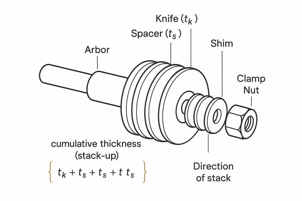
Maxtor Metal은 컨버팅 및 슬리팅 라인을 위한 맞춤형 정밀 연마 산업용 나이프를 제작합니다. 일상적인 슬리팅 작업에서 슬릿 폭 안정성(및 OEE)을 빠르게 잃는 가장 큰 원인 중 하나는 하나의 아버에 수많은 나이프, 스페이서 및 심(shim)을 쌓을 때 발생하는 작은 두께 오차를 간과하는 것입니다.
- 누적 두께 공차의 정의: 모든 개별 부품의 공차와 설정 영향이 결합된 후 조립된 나이프 팩의 총 축 방향 두께 편차.
- 누적 두께 공차가 중요한 이유: 누적 편차는 슬릿 폭의 드리프트, 클리어런스(간격) 변화, 버(burr) 발생, 가장자리 손상, 재작업 및 교체 시간 증가로 이어집니다.
- 발생 원인: 나이프, 스페이서, 아버 형상, 심(shim), 런아웃, 클램핑 왜곡, 청결도 및 온도.
- 이 가이드에서 다루는 내용: 스택업 계산법(최악 조건법 vs RSS법), 품질에 미치는 영향, 그리고 다음과 같이 엄격한 목표를 달성하기 위해 필요한 제어 루프 ±0.001 mm (공정 및 측정 시스템이 이를 뒷받침하는 경우).
- 엔지니어링 노트: 누적 두께 공차 제어는 로터리 툴링 정밀도의 한 측면일 뿐입니다. 축 방향 런아웃 표준 및 재질 등급을 포함한 나이프 레벨 사양은 Maxtor Metal의 다음 페이지를 참조하십시오. 정밀 원형 슬리터 나이프에스.
누적 두께 공차의 기초
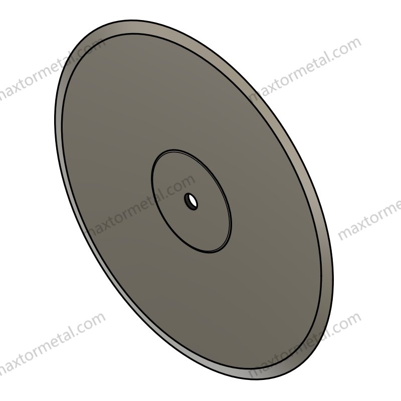
정의 및 용어
누적 두께 공차 (스택업) 은 여러 부품을 직렬로 결합할 때 조립된 스택 높이에서 예상되는 최대 편차입니다. 다중 나이프 슬리팅 라인에서 이 스택 높이는 나이프와 스페이서의 축 방향 위치를 결정하며, 이는 결과적으로 클리어런스와 최종 슬릿 폭 및 가장자리 상태를 결정합니다.
이 문서에 사용되는 주요 용어:
- 공칭 두께: 나이프 또는 스페이서의 목표 두께.
- 용인: 공칭 두께로부터 허용되는 편차 (주로 양방향 공차, 예: ±0.003 mm).
- 스택 높이: 라인 내 모든 구성 부품 두께의 합.
- 축 방향 이동 (Axial shift): 누적된 편차로 인해 스택 전체에 발생하는 순 위치 오차.
- TIR (총 흔들림): 부품이 회전할 때 측정되는 편차로, 두께가 완벽하더라도 “동적” 요인으로 작용할 수 있습니다.
스택 오차의 원인
스택 오차는 단순히 “나이프 자체”만의 문제가 아닙니다. 이는 부품 편차와 실제 조립 환경이 결합된 결과입니다.
- 나이프 두께 공차 (및 유효 두께에 영향을 미치는 평행도/평탄도).
- 스페이서 두께 공차 (스페이서의 개수가 많기 때문에 종종 가장 큰 누적 요인이 됩니다).
- 아버 숄더, 저널 및 안착면 (축 방향 기준 형상 및 마모).
- 심 (Shim) (두께 공차 + 취급 중 손상).
- 런아웃 / 흔들림 (TIR) (아버 상태, 베어링 마모, 찍힘, 버 또는 편심 보어 등으로 인해 발생).
- 클램프 왜곡 (토크, 팩 압축 및 불균일한 접촉으로 인해 발생).
- 온도 (장비 예열, 마찰열, 주변 온도 변화).
핵심 요점: 엄격한 슬릿 폭 공차를 목표로 할 때는 런아웃, 청결도, 열 상태를 단순한 “설정 노이즈”가 아닌 주요 스택 영향 요인으로 취급해야 합니다.”
Impact on slit width and edges
Cumulative thickness tolerance matters because it changes where the knife edges actually run under load.
Common symptoms when stack-up isn’t controlled:
- 슬릿 폭 변화 across lanes or across time (start vs warm operation).
- Burr formation because clearance shifts out of the stable window.
- Edge tearing/fuzzing on films and nonwovens when the cut transitions from shear to rub.
- Knife collisions or scuffing when cumulative axial shift eliminates safe side clearance.
The practical link to OEE is straightforward: width and edge issues increase scrap and line interruptions, while frequent “micro-adjust” stops extend changeovers.
스택업 분석 방법 및 사례
This is where tolerance stack-up becomes a practical tool: you choose a method, run the numbers, and then decide what you must control (and what you can safely leave looser).
Worst-case vs RSS stack-up
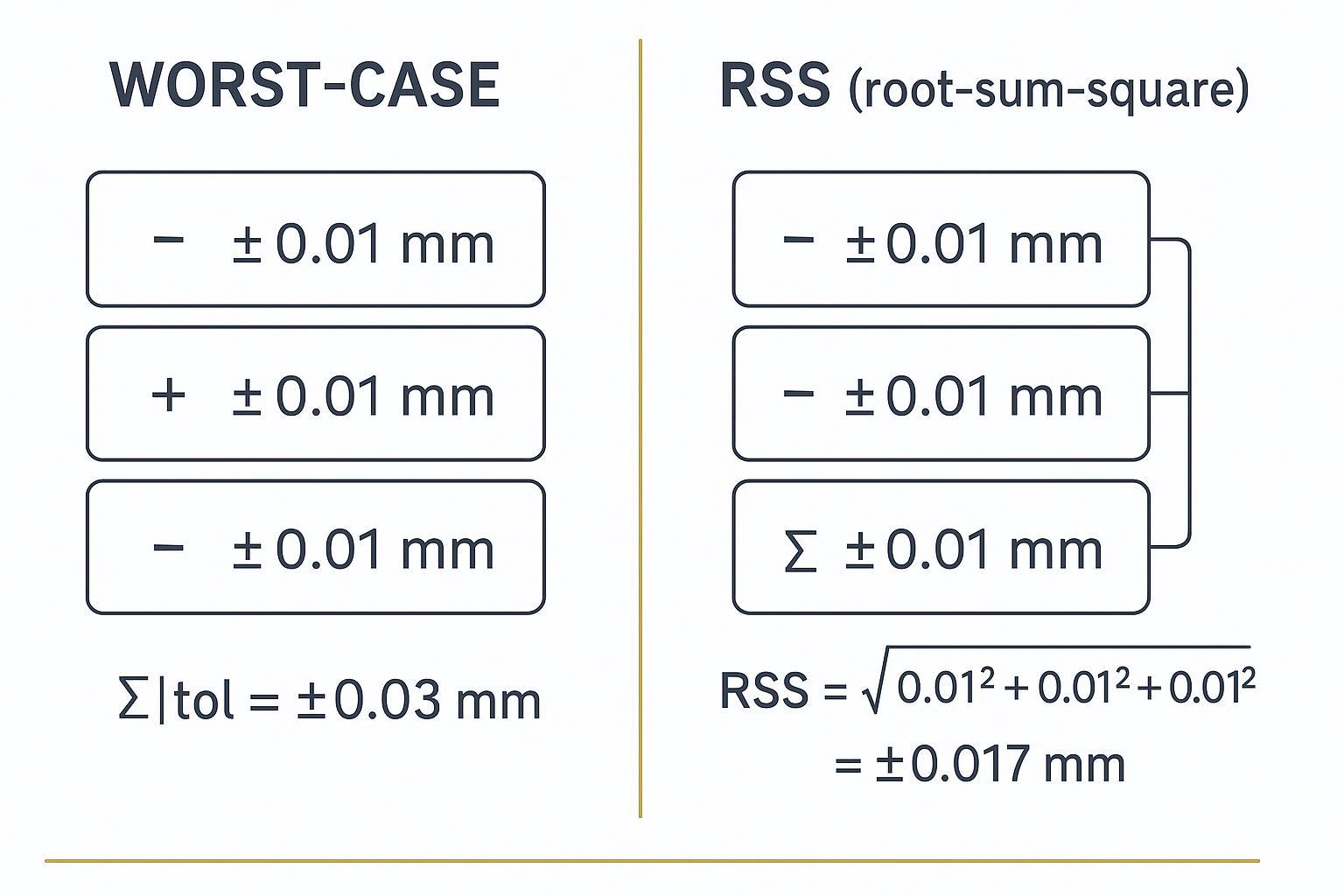
There are two common ways to estimate cumulative thickness tolerance. They answer different questions.
- Worst-case assumes every contributor hits its extreme limit in the same direction.
- RSS (root-sum-square) assumes contributors are largely independent and random, so extremes rarely align.
Use cases:
- 사용 worst-case to protect against hard interference limits (fit, collision risk).
- 사용 RSS to estimate expected production variation when the process is stable and measurement is credible.
A simple way to keep the math honest: RSS is a prediction, but your first-article width and edge data is the truth—use production data to validate or update the tolerance budget.
For a clear engineering overview of both methods and their assumptions, see Enventive’s explainer on worst-case, RSS, and Monte Carlo in tolerance stackups (2024).
For broader GD&T and tolerancing context, many engineering teams also reference standards frameworks such as ASME Y14.5 Dimensioning and Tolerancing and the ISO limits-and-fits system (e.g., ISO 286-1:2010) when defining tolerances and interpreting stack-up risk.
Numeric example for a multi-knife lane
Consider a single lane with:
- 1 top knife + 1 bottom knife (thickness variation affects how the pack seats)
- 8 spacers
- 2 shims
If each spacer is specified at ±0.003 mm, the shims at ±0.002 mm, and each knife at ±0.002 mm, then:
Worst-case stack tolerance (simple bilateral sum):
- Spacers: 8 × 0.003 = 0.024 mm
- Shims: 2 × 0.002 = 0.004 mm
- Knives: 2 × 0.002 = 0.004 mm
- Total worst-case = ±0.032 mm
RSS estimate (assuming independence):
- RSS = √(8×0.003² + 2×0.002² + 2×0.002²)
- RSS = √(8×9e-6 + 4×4e-6)
- RSS = √(72e-6 + 16e-6) = √(88e-6) ≈ ±0.0094 mm
Both numbers can be “right,” depending on what you’re trying to protect.
Building a tolerance budget
A tolerance budget makes stack-up actionable instead of theoretical.
- Define the output you care about
- Slit width tolerance (e.g., ±0.05 mm) or side clearance window.
- List contributors and classify them
- Random (measurable scatter): thickness variation of ground spacers.
- Systematic (bias/correlation): clamp torque procedure, warm-up state, dirty seating faces.
- Allocate budget by leverage (impact) and controllability
- Many shops get more benefit by tightening spacer control and runout than by over-tightening every knife thickness.
- Bind the budget to measurement confidence
- If your micrometer + method can’t reliably resolve the tolerance band, the budget is paperwork, not control.
A practical rule for stack components: the more pieces you have in series, the more you should consider measured-and-matched sets instead of trusting nominal labels.
미니 케이스 스터디: 연포장 필름 슬리팅 (BOPP/PE)
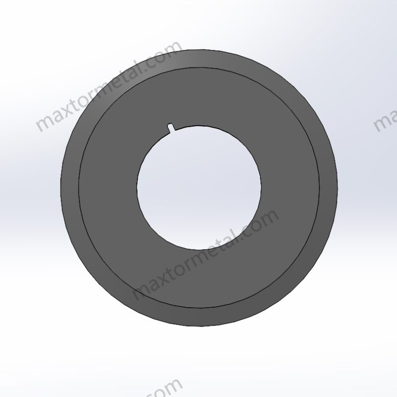
The data below comes from Maxtor Metal’s project support for a flexible packaging film converter; the customer name has been anonymized.
The fastest way to make stack-up “real” is to tie it to one lane’s numbers. The following anonymized example comes from a flexible packaging film converter running a differential rewind slitting line.
셋업
- Material/process: BOPP / PE flexible packaging film
- Knife stack (per setup): 18 circular slitter knives, 36 spacer/separator rings, thin shims used for final width correction
- Knife shaft diameter: 120 mm
Original problem
After knife changes, the converter saw slit width drift, light edge burrs, and unstable setup repeatability (repeat customer complaints).
Control actions implemented
- Spacer rings measured individually and marked
- Spacers sorted in 0.001 mm thickness groups 그리고 paired/matched during assembly
- Defined tightening torque + tightening sequence, 와 함께 pre/post-torque TIR recorded each setup
- Added a cleaning + deburring procedure for all knife/spacer contact surfaces
Results (before vs after)
| 미터법 | Before improvement | After improvement |
|---|---|---|
| 슬릿 폭 변화 | ±0.080 mm | ±0.025 mm |
| 버/모서리 결함률 | 4.8% of rolls | 1.2% of rolls |
| 전환 시간 | 52 min | 34 min |
| 토크 전/후 TIR | 0.014–0.018 mm | 0.005–0.007 mm |
| Spacer thickness spread (total) | 0.006mm | 0.002mm |
Measurement notes (what made the data defensible)
One detail worth calling out: the converter didn’t start by switching knife materials or changing suppliers. The first gains came from making the stack measurable and repeatable (spacer matching, torque discipline, and TIR logging) and then letting the data drive whether tighter part tolerances were justified.
- Spacer thickness measured using a digital micrometer with 0.001 mm resolution
- Measurement repeated 3 times per spacer
- Measurements performed in a temperature-controlled inspection room (~20°C)
- First-roll slit width and edge condition recorded after each setup; stability maintained across 3 consecutive production batches
Takeaway: Before tightening knife thickness specs to micron levels, stabilize the 체계: match spacers by measured thickness, standardize torque, and log pre/post-torque TIR. In many real lines, these controls deliver faster and larger gains than tightening a knife-only callout on paper.
Case study template (copy/paste)
- Material + slitting method:
- Knife count / spacer count / shim use:
- Target slit width tolerance:
- Spacer thickness spread (min/max or total):
- Pre/post-torque TIR:
- Before/after: width variation, edge defect rate, changeover time:
- Measurement method + temperature condition + repeat count:
정밀도 목표 및 공정 능력
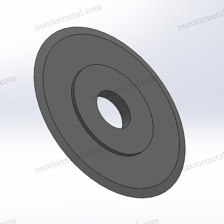
Typical vs high-precision specs
Not every slitting line needs micron-class thickness tolerance.
Typical bands you’ll see in converting and slitting:
- General film/tape/paper slitting: thickness tolerance around ±0.005 mm can be reasonable when combined with good setup discipline.
- Heavier-duty or more demanding lines: ±0.003 mm 사용될 수 있습니다.
- 초정밀 응용 분야 (박막/전극, 정밀한 에지 품질): ±0.001 ~ ±0.002 mm 이 지정되기도 합니다.
이러한 범위는 다음에 게시된 응용 지침과 일치합니다. Maxtor Metal circular knives and blades 제품 페이지 (날당 두께 편차가 너무 크면 다중 블레이드 갱 전체의 누적 오차로 인해 버(burr)가 발생하거나 충돌이 발생할 수 있다는 명확한 주의 사항 포함).
±0.001 mm가 정당화되는 경우
에이 ±0.001 mm 두께 목표는 도구이지 훈장이 아닙니다. 다음 중 최소 하나 이상에 해당할 때 정당성을 가집니다.
마이크론 수준의 목표로 상향하기 전에, 한 가지 빠른 현실성 점검과 의사 결정 단계를 거치십시오.
- 측정 능력 점검 (신속 스크리닝): 귀하의 마이크로미터/비교기, 측정 방법 및 환경이 1–2 μm 의 차이를 동일 부품에서 일관되게 구별할 수 없다면(동일 작업자의 반복 측정), 규격을 적용할 준비가 되지 않은 것입니다. ±0.001 mm 생산 단계에서.
- 의사 결정 단계 (Go/No-Go): 다음 조건이 충족되지 않는 한 규격을 강화하지 마십시오. ±0.001 mm (1) 공차 범위에 대해 허용 가능한 GR&R(또는 이에 상응하는 반복성 스크리닝)을 입증할 수 있고, (2) 측정 조건(측정력/고정 및 온도 상태)을 제어할 수 있으며, (3) 두께로 인한 누적 편차가 폭/에지 문제와 상관관계가 있음을 보여줄 수 없다면 말입니다.
- Decision rule: 다음으로 취급하십시오. ±0.001 mm as a 시스템 사양 (부품 + 측정 + 열 제어 + 설정 절차)으로 취급해야 하며, 나이프 단독 사양으로 취급해서는 안 됩니다.
- 슬릿 제품의 공차가 매우 타이트하여, 누적으로 인한 축 방향 변위가 폭 허용 오차를 너무 많이 소모합니다.
- 클리어런스(간격)의 프로세스 윈도우가 좁습니다 (범위를 벗어나면 에지 품질이 급격히 저하됨).
- 팩에 장착된 나이프 수가 많아 부품당 “작은” 공차가 실제 축 방향 드리프트로 이어집니다.
- 런아웃, 정렬 또는 장력이 아닌 두께 편차가 주요 원인이라는 증거가 있습니다.
측정 및 공정 능력을 검증할 수 없다면, ±0.001 mm 사양은 스크랩 감소나 가동 시간 개선 없이 비용만 증가시킬 수 있습니다.
공정 능력, Cp/Cpk 및 GR&R
두 가지 점검을 통해 정밀도 목표의 신뢰성을 유지합니다.
- GR&R (게이지 반복성 및 재현성): 측정 시스템이 충분히 안정적인지 확인합니다. 측정 노이즈가 공차 범위에서 큰 비중을 차지하면 무의미한 오류를 쫓게 됩니다.
- Cp/Cpk: 공정 출력(슬릿 폭, 에지 결함, 클리어런스 측정값)이 능력을 갖추고 중심에 맞춰져 있는지 확인합니다.
실질적인 기대치:
- Cpk가 낮다면 나이프 공차를 더 타이트하게 요구하는 것부터 시작하지 마십시오. 먼저 공정이 중심에서 벗어났는지(설정 편향), 아니면 실제로 변동성이 너무 큰지(부품 산포) 확인하십시오.
- GR&R이 취약하다면 사양을 변경하기 전에 측정 장비, 고정 장치, 방법 및 환경을 개선하십시오.
제조 및 측정 프로세스
재료, 열처리 및 응력 제거
두께 공차 안정성은 연삭 전부터 시작됩니다.
- 재료 선택 은 열처리 후 연삭 및 변형을 얼마나 예측할 수 있는지에 영향을 미칩니다.
- 열처리 및 응력 제거 는 평탄도, 평행도 및 장기 안정성에 영향을 미칩니다.
- 공정 문서화 는 에지 품질이 저하될 때 근본 원인 분석 작업을 가능하게 하므로 중요합니다.
실제로 모든 배치를 자재 성적서, 열처리 기록 및 검사 결과와 연계할 수 있을 때 “측정 경로”가 가장 강력해집니다. Maxtor Metal는 자재 성적서, 열처리 기록 및 부품 검사 로그를 통해 배치 수준의 추적성을 유지하며, 이는 설치 후 에지 품질이 저하될 때 근본 원인 분석 작업을 가능하게 하는 문서화 자료입니다.
연삭, 래핑 및 표면 조도
마이크론 수준에서 두께를 제어하려면 이를 위해 설계된 공정 선택이 필요합니다.
- 평행 연삭 전략 (단순히 에지 형상뿐만 아니라) 두께 일관성을 위해 설계되었습니다.
- 연삭 중 열 제어 변형을 줄이기 위해.
- 래핑 또는 정밀 연삭 when surface and parallelism drive fit.
Surface finish also shows up downstream as edge quality and contamination:
- For high-speed film converting, very smooth faces reduce friction and debris.
- For abrasive coatings or filled polymers, finish requirements and edge prep should match the wear mode.
Gauging, environment, and traceability
When targets approach ±0.001 mm, treat measurement as an engineered system:
- Gauging: use calibrated micrometers/comparators suited for microns; document force technique.
- 환경: temperature stability matters; measure at defined thermal states.
- Traceability: keep calibration records and part-level inspection logs so “good parts” are defensible.
If you’re buying precision components internationally, traceability plus a predictable import workflow reduces two common failure modes: (1) you can’t prove what you received, and (2) the parts arrive late and force an emergency changeover plan.
슬리터 설정 및 유지보수
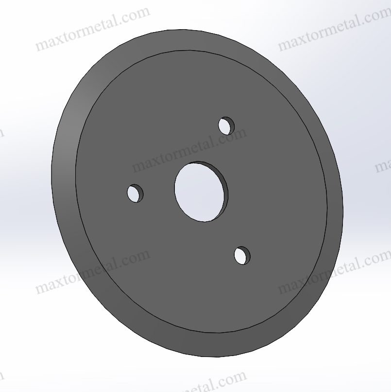
Arbor and runout checks
Runout can dominate stack-up. A thin film line may tolerate modest variation; a tight-width, high-speed job may not.
For a deeper look at how central bore tolerance and ISO 286 fit selection affect assembled TIR—and a verification routine to keep runout repeatable across changeovers—see 중앙 내경 공차 및 런아웃: 고속 슬리터 나이프의 ISO 286 적합성 최적화.
점검 사항:
- Arbor journal condition (nicks, wear bands).
- Shoulder seating faces (burrs, trapped debris).
- Bearing condition (heat, vibration signatures).
- Assembled pack TIR after torque.
If you need a technical refresher on how alignment and movement upstream of the slit point affect achievable tolerances, Parkinson Technologies discusses practical constraints in Achieving Tight Tolerances with Wrap Shear Slitting (2023).
Spacer calibration and match grinding
Spacer control is often the highest-return improvement because it’s both measurable and repeatable.
A workable spacer discipline:
- Measure every spacer and mark the actual thickness.
- Sort into bins by measured value (e.g., 0.001 mm increments).
- Build lanes using matched sets rather than random pulls.
- Re-measure after any damage event, polishing, or suspected burr.
Match grinding (or lapping) becomes relevant when:
- You need repeatable lane widths across many packs,
- You want to reduce the number of shims used, or
- You need predictable behavior after torque.
Clamp torque, overlap, and alignment
Even a “perfect” stack can fail if assembly bias is uncontrolled.
- Torque: define a procedure (tool, torque value, sequence) and keep it consistent.
- Overlap and side clearance: set to the material and process window; verify after torque.
- 조정: ensure top/bottom knife relationship is stable across the run.
A simple but effective control is to record three numbers each setup:
- pre-torque TIR
- post-torque TIR
- first-article width and edge inspection result
If those three are stable, your tolerance budget has a chance of being real.
For lines running thin films or nonwovens where holding a fixed clearance is impractical, see how spring-loaded zero-clearance setups handle this: 스프링 장착형 설정을 통한 제로 클리어런스 전단 슬리팅.
경제성 및 리스크 트레이드오프
OEE and scrap cost model
Cumulative thickness tolerance problems typically cost money in three places:
- 권투 시합: width out-of-spec or edge defects.
- 중단 시간: extra time to chase clearance and re-stack packs.
- Tooling life: rubbing and collisions shorten knife life and increase regrind frequency.
A quick model you can apply:
- Scrap cost per hour = (scrap rate %) × (throughput) × (material cost)
- Downtime cost per event = (minutes lost) × (line $/minute)
- Tooling cost delta = (extra regrinds + replacements) × (unit cost)
When you quantify those three, it becomes clear when “tighter tolerance” pays back—and when it doesn’t.
Lead time and tooling cost impacts
Tighter tolerances usually increase:
- grinding and inspection time,
- rejection rate at the supplier,
- metrology requirements (and therefore cost).
They can also reduce total cost if they cut setup time and scrap enough to dominate the tooling premium. The only way to know is to bind tolerances to measured outcomes (width scatter, edge defect rates, and changeover minutes).
Decision flow for precision level
Use this decision flow to choose a precision level without guessing:
- Is the defect clearly tied to runout/alignment/cleanliness?
- Yes → fix setup and maintenance first.
- No → continue.
- Does measured lane-to-lane width variation correlate with measured component thickness variation?
- Yes → tighten the tolerance budget where it contributes most (often spacers first).
- No → continue.
- Can your measurement system pass GR&R for the tolerance band?
- No → upgrade measurement and environment.
- Yes → continue.
- Does the scrap + downtime model justify the premium for tighter components?
- No → keep a practical spec (±0.003 to ±0.005 mm) and improve controls.
- Yes → pursue ±0.001 mm with full traceability and capability checks.
가정 및 적용 가능성 (과도한 사양 지정 방지)
A stack-up calculation is only as good as its assumptions. Use this guide with the following practical boundaries:
- Worst-case vs RSS: worst-case protects against hard interference limits (rubbing/collision risk). RSS estimates typical variation when contributors are mostly independent.
- Correlation matters: parts from the same grinding batch, the same clamping procedure, or a consistent setup bias can make errors move together. If you see correlation, RSS can under-predict—use worst-case for safety and verify with real measurements.
- Micron targets require a capable measurement system: before specifying ±0.001 mm, confirm your measurement method, force control, and temperature conditions can resolve the band. If the gage can’t pass GR&R at that tolerance, you’ll make decisions based on noise.
For deeper background on measurement system analysis (GR&R/MSA) and capability indices (Cp/Cpk), see ASQ’s overview of Gage R&R, AIAG’s description of the MSA-4 Measurement Systems Analysis manual, ASTM’s E2782 guide for Measurement Systems Analysis (MSA), and JMP’s primer on process capability.
결론
Cumulative thickness tolerance in multi-knife slitting is a stack-up problem: small errors in knives, spacers, shims, arbor geometry, runout, and thermal state add together and show up as width drift, edge defects, and lost OEE. The fastest path to stability is to treat the whole system—components + measurement + setup—as one tolerance budget you can verify.
Based on Maxtor Metal’s measured experience supporting multi-knife slitting projects, controlling spacer thickness and assembly discipline often delivers faster improvements than simply tightening a knife thickness tolerance on paper.
Immediate steps you can apply this week:
- Measure arbor and assembled-pack TIR before and after torque.
- Start a spacer measurement-and-sorting discipline (actual thickness marking).
- Separate worst-case (hard interference) from RSS (expected variation) in your tolerance math.
- Confirm GR&R before declaring a micron-level spec “necessary.”
Quick reference (formulas + setup checklist)
Tolerance stack-up math
- Worst-case stack tolerance (hard-interference safety):
T_WC = Σ |t_i| (i = 1..n)
- RSS stack tolerance (expected variation when contributors are mostly independent):
T_RSS = sqrt(Σ (t_i^2)) (i = 1..n)
Typical thickness tolerance targets (rule-of-thumb)
These are starting points—validate them against your slit-width spec 그리고 measurement capability.
- ±0.005 mm: general converting where setup discipline is strong and clearance window is forgiving
- ±0.003 mm: demanding lines or higher knife/spacer count stacks
- ±0.001 ~ ±0.002 mm: ultra-precision jobs only when GR&R and process capability justify it
Setup checklist (record on every changeover)
- Clean shoulders, seating faces, and spacers (no burrs, trapped debris)
- 기록 pre-torque TIR 그리고 post-torque TIR
- Verify overlap/side clearance after torque
- 측정하다 first-article width + perform edge inspection (burr/fuzz/tearing)
- Log spacer actual thickness (measured-and-matched sets)
To keep improvements from fading, keep these documents on file:
- component inspection records (thickness, parallelism, finish)
- gauge calibration and GR&R reports
- setup check sheets (torque method, TIR, first-article results)
- tolerance budget worksheet tied to your slit-width spec
FAQ
What is cumulative thickness tolerance in slitting?
It’s the total possible variation in an assembled knife/spacer stack height after all individual thickness tolerances and setup effects combine. In multi-knife slitting, that cumulative variation can shift axial positions enough to change clearances and slit width.
How do you calculate tolerance stack-up for multiple spacers and knives?
Use worst-case (sum of absolute tolerances) to protect against hard interference limits, and RSS (root-sum-square) to estimate expected variation when contributors are independent and the process is stable. Then validate with measured parts and first-article results.
Worst-case vs RSS tolerance analysis: which should I use for slitter tooling?
Use worst-case when a clearance loss could cause rubbing or collisions, because it’s conservative. Use RSS to estimate typical width variation in stable production, because it reflects how random variation usually behaves.
How does arbor runout (TIR) affect slit width and burrs?
Runout creates dynamic axial variation as the pack rotates, which can push clearances in and out of the stable window. That can cause intermittent rubbing, burrs, heat, and accelerated wear even if thickness tolerances look fine on paper.
When is ±0.001 mm knife thickness tolerance actually necessary?
It’s necessary when your width/edge process window is narrow, your knife count makes cumulative error meaningful, and you can prove (with measurement and correlation) that thickness variation—not alignment or tension—is the dominant driver. It also requires a measurement system capable of resolving microns.
What GR&R should I expect if I’m trying to control micron-level thickness?
Your measurement system variation must be small compared to the tolerance band, or you’ll make wrong decisions based on noise. If GR&R is poor, improve instrument selection, fixturing, method, and temperature control before tightening component specs.
Why do spacers cause so much stack-up error in multi-knife slitting?
Because there are many of them in series. Even a small per-spacer tolerance becomes large when multiplied across the stack, so measured-and-matched spacers often deliver more improvement than tightening a single knife spec.
How do I reduce slit-width variation without buying new knives?
Start with setup controls: clean seating faces, verify arbor and pack TIR, standardize torque, and calibrate/sort spacers by measured thickness. These steps often reduce variation faster than changing suppliers or materials. Additionally, verify if the blade’s bevel geometry matches the mechanical resistance of your material profile.
After-sales Engineer: Jerry Chu
Title: Technical Support Specialist
조직: 애프터 서비스
Reviewed by: Maxtor Metal QA Team
경험: 10 years, cross-industry applications (papermaking, plastic crushing, metal slitting, woodworking). Focused on solving on-site issues such as cutting burrs and excessive dust.
자격증: PMP, CMRP

 English
  Spanish
  Italian
  French
  Portuguese
  Russian
  German
  Arabic
  Hindi
Hindi  Vietnamese
  Indonesian
  Japanese
  Korean