

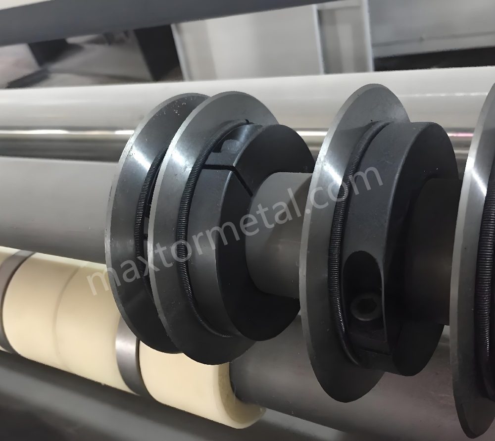
고속 슬리팅은 매우 엄격합니다. 원형 나이프가 정확하게 회전하지 않으면 나이프가 "무뎌지기" 전에도 절단면 품질이 저하됩니다. 이 기사에서 Maxtor Metal은 중심 구멍(central bore) 공차와 런아웃(구멍 크기 및 형상이 고속 회전 시 에지 TIR로 나타나는 방식)을 사양으로 지정할 수 있는 수치와 반복 가능한 검사 방법으로 연결하여 설명합니다.
엔지니어링 참고 사항: 축 방향 런아웃 표준 및 재질 등급을 포함한 칼날 사양은 다음을 참조하십시오. Maxtor Metal의 정밀 원형 슬리터 나이프.
- 동적 런아웃이 고속 슬리터에서 칼날 품질과 OEE(설비종합효율)를 저하시키는 이유: 불균일한 맞물림, 열 발생, 버(burr) 및 조기 칼날 손상을 유발하고, 추가적인 셋업 시간과 스크랩을 발생시키기 때문입니다.
- 중앙 보어 공차 런아웃 제어 및 끼워맞춤 선택이 절삭날의 안정성을 높이는 방법: 보어는 1차 기준면 역할을 하며, 보어의 크기와 기하학적 형상은 센터링 반복 정밀도와 고속 회전 시 스택의 거동에 영향을 미칩니다.
- 독자가 얻을 수 있는 핵심 내용: 수치적 목표, 끼워맞춤 선택, 조립 점검: 런아웃 목표 범위, ISO 286 끼워맞춤 공차역 (50 mm 예시), 시간 경과에 따른 편차를 방지하는 검증 루틴.
런아웃 증폭
기하학적 구조에서 동역학으로
정지 상태에서 런아웃은 단순한 기하학적 오차로 보입니다. 즉, 칼날의 절삭 원이 아버(arbor) 축과 완벽하게 동심을 이루지 않는 것입니다. 그러나 고속 회전 시 이 오차는 힘의 불균형 문제로 전환됩니다.
보어에서의 미세한 편심은 절삭 반경이 시스템에서 가장 긴 레버 암(지레대) 역할을 하기 때문에 칼날 끝에서 더 큰 영향으로 나타납니다. 또한 런아웃은 누적 공차(stack-up), 이므로, 조립된 전체 흔들림(TIR)은 아버 TIR, 보어/외경 동축도, 스페이서 평행도, 숄더 직각도, 클램핑 면의 결합된 영향을 반영합니다. 이는 여러 기준면에서 발생하는 전형적인 공차 누적 현상입니다.
즉, 아버 보어 끼워맞춤 런아웃 누적 이 일반적인 고장 모드입니다. 몇 가지 미세한 요인들이 합쳐져 눈에 보이는 칼날 끝의 문제로 이어집니다.
요약하자면: 칼날 교체 시 런아웃이 “변동”한다면, 이는 대개 칼날 외경의 문제가 아닙니다. 보어 끼워맞춤, 단면, 스페이서, 안착 상태 등 위치 결정의 반복 정밀도 문제입니다.
다축 칼날(multi-knife) 구성에서 스택 반복 정밀도는 칼날과 스페이서 전체의 두께 편차가 어떻게 누적되는지에 따라서도 달라집니다. 실무적인 문제 해결 방법은 다음을 참조하십시오: 다축 칼날 슬리팅에서 누적 두께 공차 제어.
박판 디스크의 유연성
슬리터 칼날은 직경에 비해 두께가 얇은 경우가 많습니다. 이는 클램핑력과 불완전한 접촉이 디스크를 탄성적으로 변형시킬 수 있기 때문에 중요합니다.
두 가지 일반적인 고장 모드:
- 런아웃을 “해결”하기 위해 강하게 클램핑하면 실제로 칼날이 휘어지거나 돌출된 부위에서 칼날이 기울어지게 됩니다.
- 미세한 단면 오차(버, 찍힘, 이물질 유입)는 보어 크기가 정확하더라도 칼날 끝의 측정 가능한 TIR로 이어지는 기울어짐을 유발합니다.
단면 흔들림이 슬리팅 단면에 미치는 영향에 대해 자세히 알아보려면 다음 가이드를 참조하십시오: 슬리팅에서의 축 방향 런아웃 및 칼날 품질.
요약하자면: 보어 크기 공차를 아무리 좁혀도 평탄도, 청결도, 직각도가 확보되지 않은 스택은 해결할 수 없습니다. 보어 제어는 필수적이지만 그것만으로는 충분하지 않습니다.
밸런스 및 공진
런아웃과 밸런스는 다른 개념입니다. 런아웃은 기하학적/조립 정렬 상태를 의미하며, 밸런스는 질량 분포를 의미합니다. 조립품의 밸런스가 맞지 않으면 TIR이 낮더라도 진동이 발생할 수 있습니다.
고속 슬리팅의 경우, 실무적인 지침은 대개 정밀 아버 사용과 낮은 런아웃 목표 설정에서 시작됩니다.
많은 생산 현장에서는 제품 공차와 라인 속도를 기준으로 조립된 런아웃에 대해 내부 “한계치”를 설정하여 운영합니다. 조립된 칼날 끝의 TIR이 02–0.04 mm 범위로 벗어나면, 이는 오버랩이나 측면 하중만으로 보정하려 하기보다 전체 스택(아버, 단면, 스페이서, 안착 및 클램프 상태)을 점검해야 한다는 강력한 신호입니다.
오버랩 및 측면 클리어런스가 안정화 전략의 일부라면 다음 관련 기사도 도움이 될 것입니다: 오버랩 깊이 및측면 클리어런스 최적화를 통한 안정적인 슬리팅.
특정 라인 속도 이상에서만 발생하는 채터링(chattering)으로 어려움을 겪고 있다면, 이를 시스템 문제로 취급해야 합니다. 런아웃 + 밸런스 + 강성 + 감쇠가 결합되어 공진 임계값을 초과할 수 있습니다.
요약하자면: 두 가지 합격 기준을 설정하십시오. (1) 조립된 칼날 끝의 TIR, (2) 작동 속도에서의 진동/밸런스.
중앙 보어 공차 런아웃을 위한 끼워맞춤 선택 (ISO 286)
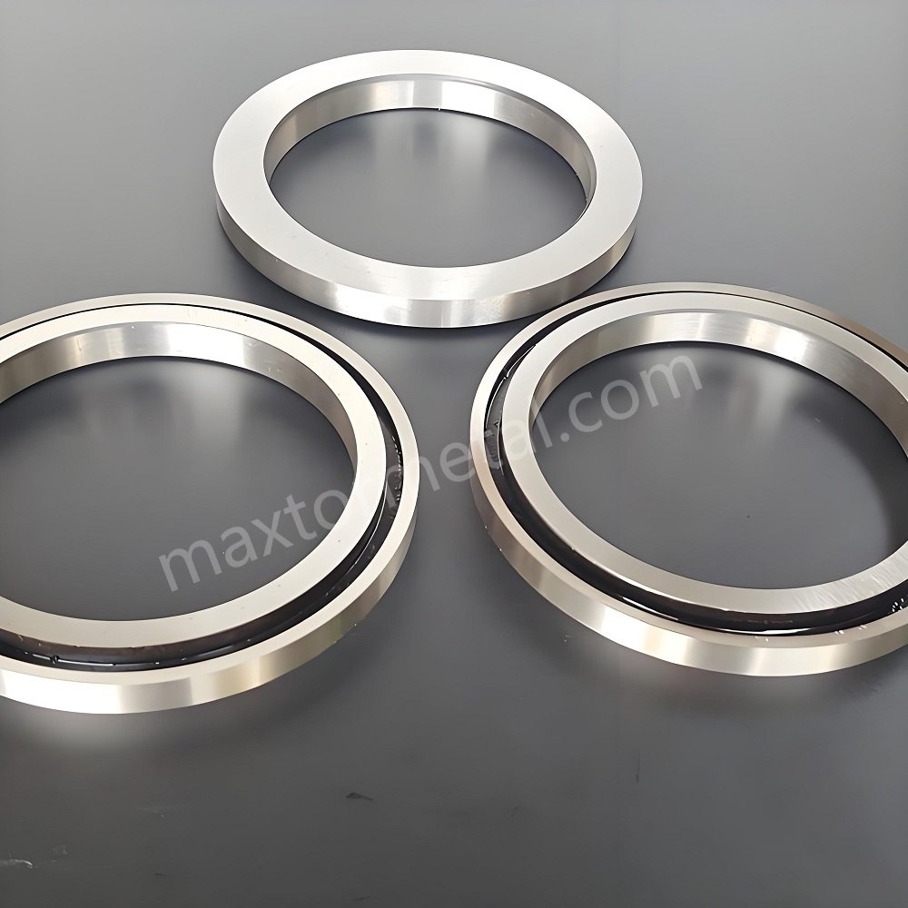
런아웃 목표와 함께 칼날 형상을 지정하려는 독자분들은 베벨(bevel) 설계에 따라 미세한 정렬 오차에 대한 절단 감도가 어떻게 달라지는지 확인해 보십시오. 자세한 내용은 원형 슬리터 칼날의 베벨 에서 실무적인 개요를 참조하십시오.
만약 ISO 286 H7 h6 g6 k6 p6 끼워맞춤 선택, 을 찾고 계신다면, 이를 실무적인 질문으로 접근하십시오: “나의 라인 속도와 공차 조건에서 조립의 어려움이나 변형 없이 반복적인 센터링을 보장하는 끼워맞춤 공차역은 무엇인가?”
50 mm 기준 중앙 보어 공차역
끼워맞춤 용어는 예측 가능한 틈새/죔새 범위를 나타내므로 매우 중요합니다.
호칭 치수 50 mm 예시의 경우, 공표된 끼워맞춤 표는 구멍 기준 공차인 H7과 몇 가지 대표적인 축 영역을 예로 보여줍니다.
Because the ISO system is defined in paid standards, use the official catalog pages below for the authoritative scope and edition details:
- ISO 286‑1: ISO code system for tolerances on linear sizes — Part 1: Basis of tolerances, deviations and fits (official catalog page): https://www.iso.org/standard/52912.html
- ISO 286‑2: ISO code system for tolerances on linear sizes — Part 2: Tables of standard tolerance grades and limit deviations for holes and shafts (official catalog page): https://www.iso.org/standard/52913.html
Use any numeric values you apply here as a practical starting point, but treat your own metrology, functional requirements, and the latest purchased edition of the standard as final—especially if you’re controlling edge TIR in the 10–20 µm range.
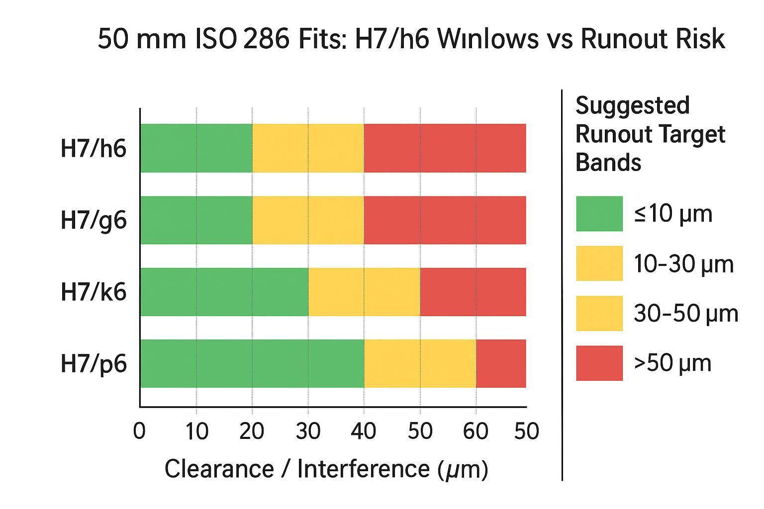
Choosing H7/h6, H7/g6, H7/k6, H7/p6
Below is the core decision logic for a 50 mm class bore/shaft interface on a slitter knife (hole basis H7; shaft tolerance class ·6). The goal is predictable centering without distortion or unstable micro-slip.
- H7/h6 (very close running / near line-to-line)
- Use when you want high centering repeatability with straightforward assembly.
- Risk to manage: fretting or pickup if surfaces are rough or contaminated.
- H7/g6 (clearance fit)
- Use when you need reliable assembly and controlled free fit, especially with frequent changes.
- Risk to manage: too much clearance can increase positional variability unless faces/pilots control location.
- H7/k6 (transition fit)
- Use when you need more location security than g6 but don’t want a true press fit.
- Risk to manage: the same parts can assemble as “easy” one day and “tight” the next; clamp distortion can also increase.
- H7/p6 (interference / press fit)
- Use only when the design intent is a press-mounted component, not a blade that must be swapped routinely.
- If you need press‑fit limits for your nominal size, calculate them using your purchased ISO 286 tables (or your company’s controlled fit calculator derived from the standard) to ensure the edition and rounding rules match your print requirements.
A practical way to connect fit choice to cutting performance is to treat fit selection as a risk control for assembled edge TIR. If your process needs ≤10 µm edge TIR, you typically can’t rely on “clearance somewhere in the stack” to self-center.
GD&T and surface finish targets
Size limits alone don’t guarantee low runout. To stop runout at the edge, you also need geometric control.
Targets to specify (typical, adjust to your product tolerance):
- Bore to OD (cutting circle) runout / coaxiality: control as a runout requirement to the bore datum; this is often more practical than trying to verify true concentricity in production metrology. For authoritative definitions and symbol rules, refer to standards catalog pages such as:
- ISO 1101:2017 — GPS — Geometrical tolerancing — Tolerances of form, orientation, location and run-out (official catalog page): https://www.iso.org/standard/66777.html
- ASME Y14.5 (GD&T) — Dimensioning and Tolerancing (official ASME catalog listing PDF): https://files.asme.org/Catalog/Codes/PrintBook/35976.pdf
- Clamping faces parallelism / flatness: keep faces flat and parallel so clamping doesn’t tilt the disc.
- Surface finish at the bore and clamping faces: smoother seating surfaces reduce high-spot tilt and improve repeatability.
핵심 요점: A “correct” ISO fit can still produce bad edge runout if bore geometry, faces, and stack flatness aren’t controlled to the same order of magnitude as your edge TIR target.
조립 및 검증
Quick acceptance spec (targets + what to measure)
| What to control | Practical target band | Where to indicate (minimum) | If you’re out of spec, check first |
|---|---|---|---|
| Assembled edge TIR (near cutting edge) | ≤10 µm (high‑precision) / 10–30 µm (general) | Near cutting edge on the assembled stack | Seating cleanliness, spacer damage/parallelism, clamp face high spots, torque sequence |
| Arbor TIR | As low as practical (verify before blaming the knife) | Arbor OD / reference surface | Bent/damaged arbor, bearing condition, shoulder squareness |
| Face wobble / axial runout | Keep to the same order as edge TIR | One knife face on the assembled stack | Burrs/dents on faces, trapped debris, spacer flatness, clamp-face parallelism |
| Bore‑to‑OD runout (knife qualification) | Align with your edge‑TIR goal (often single‑digit µm for tight processes) | Indicate OD while locating from bore datum | Bore geometry, bore finish, datum setup, grinding sequence |
| Bore fit intent (ISO 286) | H7/h6 when centering repeatability is critical; H7/g6 when changeovers dominate | Fit is a design/print requirement, not a measurement point | If runout “moves” between changes, suspect clearance + seating repeatability, not OD |
Use this table as a working baseline. Final limits should match your product tolerance, knife diameter/thickness, line speed, holder stiffness, and your measurement resolution.
Boundary conditions and common pitfalls
These recommendations are most reliable when the system is mechanically stable and your measurement method can resolve the targets.
Boundary conditions (make them explicit in your spec):
- Knife diameter vs. thickness: thinner discs are more sensitive to clamp-face errors and over-torque.
- Speed regime: higher line speed increases sensitivity to micro-slip, vibration, and resonance.
- Holder stiffness and loading: pneumatically loaded holders and worn pivots can amplify wobble.
- Process type: wrap shear slitting behaves differently from score slitting; don’t copy overlap rules across processes.
- Measurement capability: if your indicator resolution and setup repeatability are worse than the tolerance you’re chasing, you will “tune noise.”
Common pitfalls (and what to do instead):
- Only tightening bore size tolerance while ignoring faces/spacers.
- Do instead: control face flatness/parallelism and spacer condition, then verify assembled edge TIR.
- Using torque to force runout to disappear (bending the knife).
- Do instead: find the seating high spot (burr/dent/debris), correct it, and use a consistent torque sequence.
- Chasing overlap/side load first when burr appears.
- Do instead: measure arbor TIR and assembled edge TIR first; adjust overlap only after the stack is repeatable.
- Measuring only OD TIR and assuming the edge is fine.
- Do instead: indicate near the cutting edge and one face to catch wobble and tilt.
- Skipping re-seat verification and accepting a one-time reading.
- Do instead: re-seat once (clean → reassemble → remeasure). If TIR shifts materially, fix repeatability before changing knife geometry.
Arbor, spacers, cleanliness, torque
If you want runout to stay low over weeks—not just on a fresh setup—treat assembly as a controlled process.
Checklist (field-practical):
- Verify arbor seat and shoulder are clean, burr-free, and undamaged.
- Clean blade bore and clamping faces; remove adhesive, oil film, and embedded particles.
- Inspect spacers for flatness/parallelism; reject visibly dented or galled spacers.
- Use consistent torque and clamping sequence; avoid “over-tightening to fix runout.”
- Mark orientation for repeatability if you disassemble and reassemble frequently.
Measuring edge runout and concentricity
For slitter knives, measurement method matters as much as the number.
A solid routine (how to measure TIR slitter knife repeatably):
- Measure arbor TIR first (so you don’t blame the blade for a bent or damaged arbor).
- Then measure assembled TIR at:
- OD
- near the cutting edge (function-driving)
- one face (to detect wobble)
- Repeat the check after re-seating once. If TIR changes materially, the problem is seating repeatability, not “randomness.”
Many shops use edge TIR target bands that align with product tolerance and speed:
- High-precision slitting: aim around ≤0.01 mm (10 µm) edge TIR
- General industrial slitting: often 01–0.03 mm
- Investigate aggressively if you approach the 0.02–0.04 mm band described in broader setup guidance, because edge quality and tool life typically degrade quickly beyond that.
- Maxtor Metal supplies inspection traceability records — including runout measurement, material certification, and heat-treat documentation — to support incoming quality verification and assembly repeatability.
If you’re also evaluating knife manufacturing controls and verification capability, see Maxtor Metal circular slitter knives and blades for materials options and typical runout verification practices.
Balance grades and spin checks
Once geometry and assembly are under control, balance keeps vibration from reintroducing dynamic runout.
Practical steps:
- Balance the assembly you actually spin (knife + clamp + spacers) when possible.
- Select a balance grade appropriate to your speed and sensitivity (common starting points are G 6.3 for general rotating assemblies and tighter grades like G 2.5 for higher-precision/high-speed needs).
- If you need to formalize acceptance, use the purchased standard edition for the calculation and verification method. Official catalog pages:
- ISO 1940‑1:2003 — Mechanical vibration — Balance quality requirements for rotors in a constant (rigid) state — Part 1: Specification and verification of balance tolerances: https://www.iso.org/standard/27092.html
사례 연구: PET 필름 슬리팅 런아웃 안정화 (익명화)
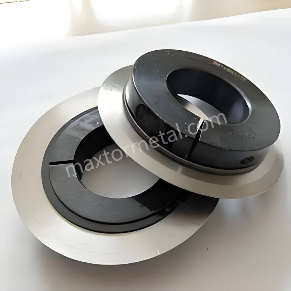
Application / industry: Flexible packaging PET film slitting (web converting).
Setup snapshot: circular shear slitter knives, M2 high speed steel with mirror‑polished edge finish; OD 130 mm, thickness 1.0mm, bore ID 75 mm; line speed 250–580 m/min; wrap shear slitting with pneumatically loaded top knife holders; 16 slit lanes; web thickness 23–50 µm PET used for laminated packaging structures.
The problem: “unpredictable edge drift” at high speed
Above ~500 m/min (especially on narrow slit widths below 80 mm), the line showed intermittent burr, fine PET dust, slight edge cracking during acceleration, and unstable narrow trim behavior. Operators reported that one shift could run stable for hours, while the next shift produced burr immediately using the “same settings.” The converter ultimately stopped changing knife geometry and investigated assembled edge TIR and stack repeatability.
Quantified results (before vs after)
Note: The data below comes from Maxtor Metal’s project support for a film converter; the customer name has been anonymized.
| 매개변수 | 전에 | 후에 |
|---|---|---|
| Assembled edge TIR (near cutting edge) | 18–24 µm | 6–9 µm |
| OD TIR | 12–16 µm | 4–6 µm |
| Face wobble / axial runout | 15–20 µm | 5–8 µm |
| 버/모서리 결함률 | 4.5–6% | 0.8–1.5% |
| 나이프 수명 | 38–45 operating hours | 62–78 operating hours |
| Slitting setup adjustment time | 25–40 min | 8–15 min |
The converter considered the largest improvement not just the lower defect rate, but the reduction in between‑shift variability.
What didn’t work (and why)
Attempt 1 — Increasing overlap (≈0.45 → 0.90 mm): incomplete cuts disappeared initially, but PET dust increased sharply, edge temperature rose, burr became more aggressive, and knife wear accelerated.
Attempt 2 — Increasing side load: short‑term slit stability improved, but holder vibration increased, top knife heating became visible, face wobble sensitivity worsened, and knife life dropped below 35 hours.
Root cause: stack-up + repeatability, not one “bad knife”
The team found multiple small contributors:
- bore fit inconsistency between knife batches
- spacer parallelism variation
- residual contamination during assembly
- repeat‑clamping variation
- aggressive overlap amplifying small runout errors
A key finding was that assembled edge TIR shifted significantly after re‑clamping, even when knife OD TIR alone looked acceptable.
Controls implemented (the fixes that held)
- Bore fit optimization: moved from a loose H7/g6‑style condition to a tighter controlled H7/h6 range to reduce micro‑movement and improve reassembly repeatability.
- Bore‑to‑OD runout tightening (qualification): previous acceptance ≤15 µm; new acceptance ≤5–6 µm relative to the bore datum to reduce accumulated stack‑up error in multi‑knife assemblies.
- Spacer & face parallelism control: tightened spacer flatness inspection, removed damaged spacers, and checked end‑face parallelism during PM intervals; the converter found spacer inconsistency drove assembled wobble more than knife OD alone.
- Standardized assembly procedure: arbor cleaned before every setup (lint‑free wipe mandatory), torque sequence standardized, and re‑seat + remeasure required after first clamp. Operators were not allowed to adjust overlap before TIR verification.
- Overlap & side clearance optimization: stable window: overlap 0.50–0.65 mm, light‑to‑medium side load only, cant angle ~0.6°. Reducing overlap slightly improved edge quality because the web stayed supported longer inside the wrap zone.
Measurement method (what made it repeatable)
- Indicator resolution: 0.001 mm (1 µm) dial indicator
- Measurement points: knife OD near cutting edge, knife face / axial surface
- What was measured: individual knife TIR, assembled stack TIR, post‑clamping repeatability
- Re‑seat verification: 예 (assemble → measure → disassemble/clean → reassemble → remeasure)
If assembled edge TIR shifted by more than ~3–4 µm after re‑seat, the team investigated spacers, arbor surface condition, and bore condition before touching overlap settings.
Takeaway from the project: Overlap depth alone was not the root cause. Instability came from overlap interacting with assembly variation and side load—so controlling the bore datum, faces/spacers, and re‑seat repeatability stabilized the process at speed.
Jesse Xu — Senior Quality Engineer, QA (Quality Assurance), Maxtor Metal. Jesse has 15 years of experience in custom industrial blades and slitting applications, with hands-on Failure Analysis capability to diagnose whether chipping and abnormal wear are driven by heat-treatment processes or by material segregation. Certifications: ASQ – CQE, ISO 9001 Lead Auditor, ASNT Level II.
결론
Stable high‑speed slitting is less about one “magic tolerance” and more about repeatable location. Treat the bore as a functional datum, control the stack, and verify what matters at the cutting edge.
Action checklist (use as an SOP starting point):
- Define acceptance gates: assembled edge TIR, face wobble, and (if needed) balance/vibration at speed.
- Verify the arbor first, then verify the assembled stack at the edge and on a face.
- Control what actually moves the number: seating cleanliness, spacer condition, clamp faces, and a consistent torque sequence.
- Use fit intent (e.g., H7/h6 vs H7/g6) to manage repeatability risk, not to “fix” a dirty stack.
- Build re-seat repeatability into your routine; if the number shifts after re-seat, fix repeatability before tuning overlap.
When TIR is confirmed within spec but snake cuts persist, the root cause typically shifts to tension, alignment, or air dynamics. For a diagnostic sequence that covers all four subsystem categories in film slitting, see Stopping Snake Cuts in Film Slitting: A Systems Checklist.
Maxtor Metal supports build-to-print circular slitter knives with standards-based specifications and documentation (e.g., inspection reports for runout/TIR and related geometric checks) to help teams keep performance repeatable across changeovers.
- ISO 286‑1 / ISO 286‑2 (fits & tolerances): official ISO catalog pages — https://www.iso.org/standard/52912.html 그리고 https://www.iso.org/standard/52913.html
- ISO 1101:2017 (GPS geometrical tolerancing incl. run-out): official ISO catalog page — https://www.iso.org/standard/66777.html
- ASME Y14.5 (GD&T): official ASME catalog listing — https://files.asme.org/Catalog/Codes/PrintBook/35976.pdf
- ISO 1940‑1:2003 (balance quality requirements, rigid rotors): official ISO catalog page — https://www.iso.org/standard/27092.html
- ISO 21940‑11:2016 (successor series for rotor balancing procedures/tolerances): official ISO catalog page — https://www.iso.org/standard/54074.html
- ISO 9001:2015 (quality management systems): official ISO catalog page — https://www.iso.org/standard/62085.html
메모: Many standards are paywalled. This article links only to official catalog/purchase pages and does not reproduce copyrighted tables. Always use the latest purchased edition and your internal specifications as the controlling documents.
FAQ
질문: 절단면(cutting edge)에서 슬리팅 나이프의 허용 가능한 런아웃(runout) 공차는 무엇입니까?
For many lines, a practical starting band is ≤0.01 mm (10 µm) edge TIR for high-precision slitting and 0.01–0.03 mm for general industrial slitting, with tighter targets for thinner materials and smaller knives.
질문: 구멍(bore) 맞춤을 더 타이트하게 하면 항상 런아웃이 줄어듭니까?
답변: 아닙니다. 더 타이트한 맞춤은 중심 잡기의 재현성을 향상시킬 수 있지만, 변형 위험을 높이고 오염이나 체결면 오차에 더 민감하게 만들 수 있습니다. 런아웃은 보통 아버, 체결면, 스페이서 및 클램핑 전체의 누적 오차(stack-up)로 인해 발생합니다.
How do I choose between H7/h6 and H7/g6 for a 50 mm arbor?
Use H7/h6 when centering repeatability is critical and assembly conditions are controlled. Use H7/g6 when frequent changeovers require reliable assembly and you can control runout via faces/pilots and clean, square stack components.
What should I measure first if runout suddenly increases?
Start with arbor TIR, then measure assembled edge TIR and face wobble. If readings change after re-seating, suspect burrs, debris, spacer damage, or clamp-face issues.
What’s the difference between runout and concentricity for slitter knives?
Concentricity is a more complex geometric control; in practice, shops often use runout (TIR) because it’s directly measurable with indicators and reflects the assembled functional condition.
Why does runout get worse at higher speed even if indicator TIR looks OK at rest?
At speed, small geometric errors can excite vibration, thin-disc flexibility, and resonance. That’s why balance/spin checks and stiffness/damping matter alongside static TIR.
Which balance grade should we target for high-speed slitting?
Start with a common industrial grade (often G 6.3) and tighten (e.g., G 2.5) when speed, quality requirements, or vibration sensitivity demand it. Use rotor mass and RPM to calculate permissible residual unbalance per ISO guidance.

 English
  Spanish
  Italian
  French
  Portuguese
  Russian
  German
  Arabic
  Hindi
Hindi  Vietnamese
  Indonesian
  Japanese
  Korean