

Published: 2026-05-28 | Last updated: 2026-05-28
If you’re chasing cleaner edges, less dusting, and longer knife life on a slitter/rewinder, Maxtor Metal sees the same pattern again and again: the fastest wins often come from two setup variables you can actually control—overlap depth 그리고 side clearance.
- Define overlap depth and side clearance as primary levers in shear and crush cutting.
- Link settings to edge quality, force/torque, temperature, wear, and OEE/TCO.
- Preview a computational workflow to optimize within material and machine constraints.
- Engineering Note: For knife-level specifications, including axial runout standards and material grades, see Maxtor Metal’s Precision Circular Slitter Knives.
분진 발생이 주요 품질 불만 사항인 경우(특히 위의 코팅지 사례와 같이 충전재가 함유된 기재에서), 칼날 수준의 근본 원인(Ra, 탄화물 미세조직, 셋업 공차 상호작용)은 별도의 진단 프로세스를 거쳐야 합니다. 참조: 슬리팅 분진 발생의 근본 원인 분석: 칼날 플랭크 Ra, 카바이드 미세조직 및 세팅 공차.
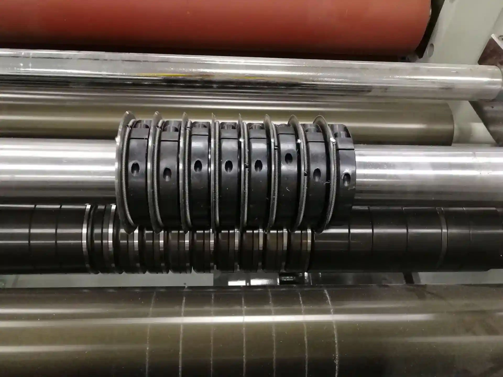
In shear slitting, overlap depth and side clearance jointly create (or destroy) a stable cut point. In crush/score cutting, the equivalent “depth” is penetration into the anvil and the “clearance” becomes alignment and pressure uniformity. Either way, these settings show up in the KPIs plants care about: edge quality, load/torque, heat, wear rate, changeover frequency, and ultimately OEE and total cost of ownership.
This article lays out a practical workflow: start with mechanics, verify with measurement, then use DOE + a Pareto lens to find a robust operating window that fits your material and machine limits.
If you’re troubleshooting today, treat it like a slitting knife setup burrs heat wear problem: get edge, load, and temperature signals on the same run, then adjust overlap and clearance in small, documented steps.
Mechanics and definitions
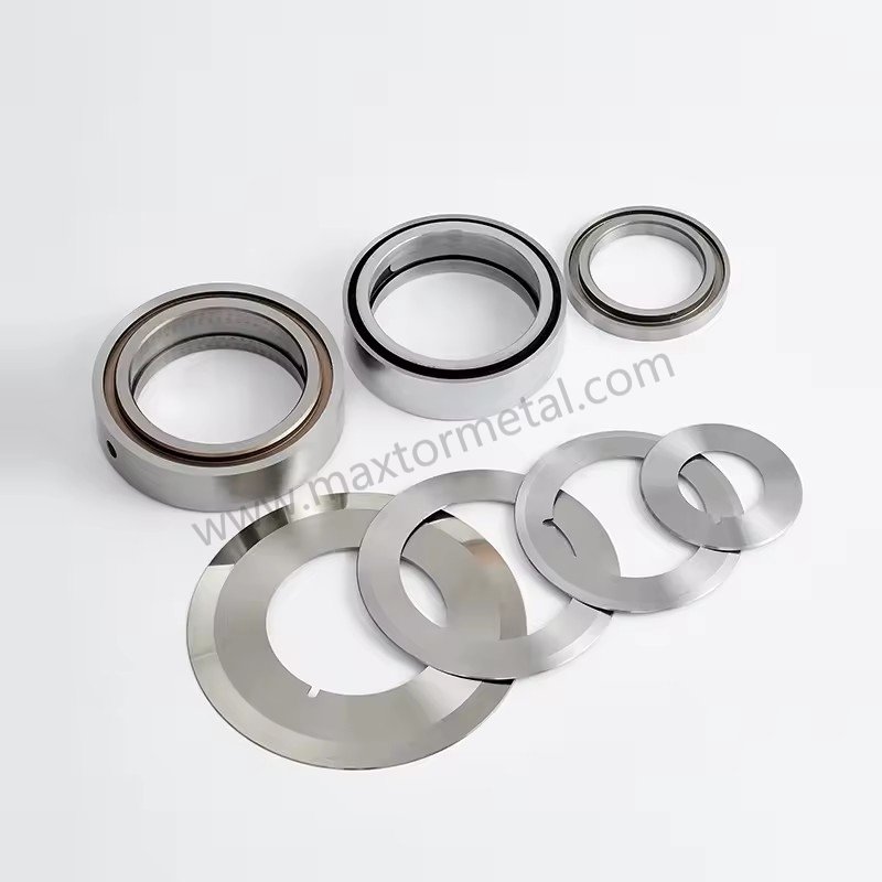
A practical way to think about shear slitting overlap depth 그리고 circular knife side clearance is that overlap sets the cut point geometry, while clearance (and the resulting side load) determines how stable that cut point stays at speed.
Overlap depth
~ 안에 shear slitting, overlap depth is the vertical intersection that ensures the knives form a true cut point. In experimental studies of shear-slitting, cutting geometry(and edge support level) and related parameters (including clearance) are shown to influence cut-surface formation and edge defects such as burr formation [1].
Practically, overlap depth is a trade-off:
- Too little overlap can let the cut point “open,” pushing the web into rubbing/sawing behavior and unstable separation.
- Too much overlap increases the contact path and rubbing, which can raise cutting load and heat and accelerate edge wear; temperature and contact conditions are well-known drivers of friction and wear behavior in tribological systems [2].
~ 안에 crush/score cutting, the same risk shows up as over-penetration: you don’t have knife-to-knife overlap, but you can still drive unnecessary compression, heat, and wear if penetration/nip is excessive. When teams compare crush cutting vs shear cutting settings, the common mistake is trying to run crush/score with shear-like “more overlap” thinking—pressure and alignment become the dominant levers.
Side clearance and side load
Side clearance is the axial/lateral relationship between the upper and lower knives (or holder and mating element) that determines how the knives stay engaged under dynamic load.
- If clearance/side engagement is too large, the web can bend or stretch locally before it fractures, which often appears as burrs, ragged edges, and unstable slit widths.
To widen the practical operating window on demanding webs, Maxtor Metal can also recommend material upgrades (for example, powder-metallurgy tool steels) and edge-prep choices based on your substrate and failure mode—then validate the result in your line’s actual clearance and runout conditions.
- If clearance is too tight, you get micro-rubbing and metal-to-metal contact—one of the fastest ways to create heat spikes and micro-chipping.
For high-speed converting, it helps to think of side clearance in two layers:
- Geometric clearance (스택업에서 설정하는 값)
- 유효 클리어런스 부하 상태에서의 유효 클리어런스(런아웃, 홀더 컴플라이언스 및 열팽창이 실제로 작용할 때 발생하는 현상)
핵심 요점: 오버랩은 절단점을 형성하며, 측면 클리어런스는 속도, 장력 변화 및 런아웃 조건에서 해당 절단점이 얼마나 안정적으로 유지되는지를 제어합니다.
힘, 열, 마모의 결합 관계
오버랩 깊이와 측면 클리어런스는 단순히 단면 외관에만 영향을 미치는 것이 아니라, 절단의 물리적 메커니즘을 변화시킵니다.
- 힘/토크 오버랩이 과도하거나 클리어런스가 너무 타이트할 때 상승하며, 이는 접촉 길이와 마찰이 증가하기 때문입니다.
- 온도 은 힘을 따릅니다. 마찰과 소성 변형이 많을수록 칼날 끝의 국부적 발열이 심해집니다.
- 마모 가속화 는 열과 측면 하중으로 인해 가속화됩니다. 일반적인 트라이볼로지(마찰학) 원리에 따르면, 마찰과 마모는 접촉 압력, 미끄럼 속도 및 온도에 크게 의존하며, 지속적인 고온 접촉은 마모 메커니즘을 가속화하고 칼날 끝의 안정성을 저하시킬 수 있습니다 [2].
이러한 결합 관계 때문에 “아직 잘 잘린다”는 말만 믿고 안심해서는 안 됩니다. 오늘 당장은 절단되더라도 발열이 심한 셋업은 결국 다음 주에 더 빠른 마모, 더 많은 분진 발생, 그리고 예상치 못한 다운타임 증가라는 결과로 돌아오게 됩니다.
Practical starting windows
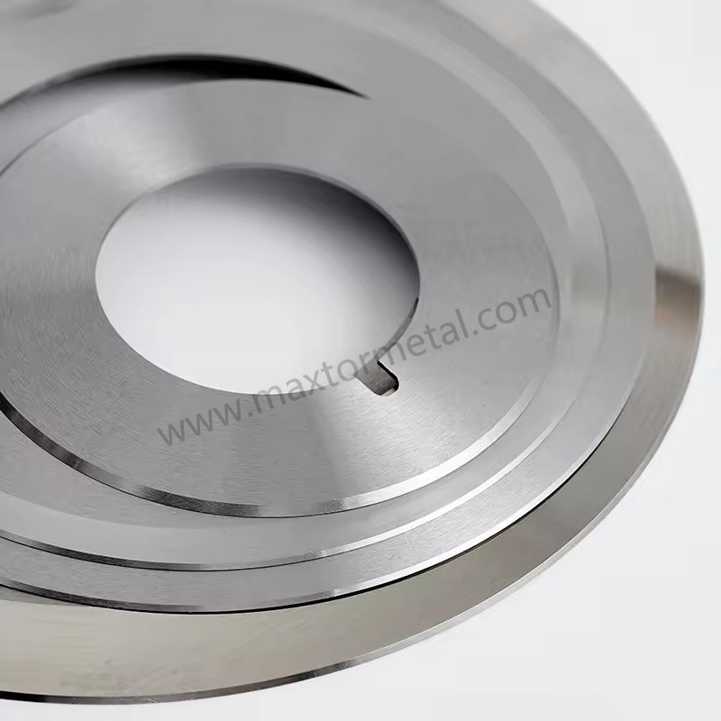
가장 안전한 접근 방식은 모든 수치 데이터를 시작 운전 범위, 로 취급하고, 실제 라인 속도에서 측정 및 단면 품질 검사를 통해 검증하는 것입니다.
제공되는 경우, Maxtor Metal는 용도별 시작 범위를 원형 칼날 및 블레이드 제품 페이지에 게시하고 있으며, 오버랩 깊이는 다음과 같은 수직 교차 깊이 범위로 설명됩니다. 5–1.5 mm, 그리고 더 단단한 기재(예: 금속 박판/단단한 폴리머)에 대한 축 방향 측면 클리어런스는 다음과 같이 명시되어 있습니다. 002–0.01 mm. 이를 보편적인 규칙이 아닌 초기 기준으로 사용하고, 사용 중인 소재와 장비의 거동에 따라 범위를 좁혀가십시오.
필름 및 라미네이트
보수적으로 시작하여 단면 검사를 통해 조정하십시오:
- Overlap depth: 낮게 시작하여 단면이 지속적으로 깨끗해질 때까지(찢어짐이나 간헐적인 미절단이 없을 때까지) 소폭으로 늘려갑니다.
- 측면 클리어런스/측면 하중: 마찰음이나 비정상적인 온도 상승 없이 절단 상태가 안정적으로 유지되는 최소 맞물림을 사용하십시오.
증상에 따른 일반적인 튜닝 방법:
- 단면 찢어짐, 간헐적인 미절단 원사, 또는 슬릿 라인의 흔들림이 발생하는 경우, 오버랩 또는 맞물림이 너무 낮을 수 있습니다.
- 단면이 녹은 것처럼 보이거나, 단면 광택 현상이 발생하거나, 칼날 주변에서 냄새/열이 발생하는 경우, 오버랩/맞물림이 너무 높거나 정렬 불량으로 인해 마찰이 강제되고 있을 가능성이 큽니다.
종이 및 판지
종이는 “절단 여부”에 대해서는 관대한 편이지만, “칼날의 수명”에 대해서는 엄격한 경우가 많습니다. 유용한 참고 패턴 중 하나는(비록 블레이드/밴드 컨텍스트이긴 하지만) 오버랩이 너무 적으면 칼날이 타고 올라가 무뎌질 수 있고, 오버랩이 너무 많으면 조기에 무뎌지며 웹에 손상을 줄 수 있다는 Valmet의 경고입니다. 이는 그들의 슬리터 조정 가이드.
실질적인 셋업 목표:
- 일반적인 장력 변동 하에서 칼날이 타고 올라가거나 간헐적인 절단이 발생하지 않을 정도로만 오버랩을 충분히 높게 유지하십시오.
- 안정적인 절단을 유지하면서 측면 하중을 가능한 한 가볍게 유지하십시오.
부직포 및 섬유
섬유질 웹의 경우, “깨끗한 단면”은 대개 섬유 풀림(fiber pull)과 보풀(fuzz)을 제어하는 것과 관련이 있습니다.
- Overlap depth: 섬유 풀림이 멈출 때까지만 늘리십시오. 그 이상으로 늘리면 보풀 대신 열이 발생하고 칼날 끝이 더 빨리 마모되는 결과를 초래합니다.
- 측면 클리어런스/측면 하중: 웹 단면을 짓누르고 보풀 발생을 증가시키는 과도한 하중을 피하십시오.
고정된 클리어런스를 유지하기 어려운 얇은 필름 및 부직포의 경우, 스프링 장착형 제로 클리어런스 홀더 방식을 사용하면 조건이 변하더라도 일관된 접촉을 유지할 수 있습니다. 다음을 참조하십시오: 스프링 장착형 설정을 통한 제로 클리어런스 전단 슬리팅.
좋은 습관은 실제 웹 장력 범위 내에서 생산 속도로 검증하는 것입니다. 저속 테스트에서는 웹의 동적 특성이 변할 때 나타나는 섬유 풀림 현상이 가려질 수 있기 때문입니다.
Measurement and instrumentation
오버랩과 클리어런스를 신뢰성 있게 측정할 수 없다면 이를 최적화할 수 없습니다. 목표는 “감각”을 추세를 파악하고 제어할 수 있는 수치로 변환하는 것입니다.
오버랩 및 클리어런스 검증
최소 측정 항목:
- 오버랩 검증 방법 사용 중인 홀더 설계에 적합한 방식(게이지/현(chord) 측정법, 다이얼 인디케이터 기준 또는 보정된 스톱).
- 축 방향 런아웃 점검 칼날 및 툴링 스택업에서의 점검. 런아웃이 불량하면 회전할 때마다 오버랩과 클리어런스가 흔들려 주기적인 단면 결함으로 나타날 수 있습니다.
- 정렬 점검 (knife squareness, holder parallelism, shaft-to-shaft alignment).
For spacer stack-up control methodology, see our companion guide on 누적 두께 허용 오차 관리.
Where Maxtor Metal’s QC processes are relevant: tight runout and thickness/flatness control on the knife itself reduces one major source of “mystery variability.” The product page describes laser interferometric axial runout verification and controlled grinding/finishing steps—useful when you’re building a setup that must hold a narrow window over long runs.
Force/torque and temperature sensing
You don’t need a lab to get meaningful signals. Aim for trends:
- Torque/drive current trending: rising torque at constant speed and tension is often your earliest sign that overlap/clearance has drifted or the edge has rounded.
- Temperature checks: use an IR spot check or thermal camera at steady state to compare setups. Heat is a proxy for friction and plastic work.
Control variable rule:
- Keep tension, speed, and web path stable during tests. Otherwise, you’ll attribute a tension change to an overlap change.
Edge quality metrology
Pick edge metrics your plant can measure consistently:
- Burr / feathering severity (simple graded scale with photo standards)
- Dusting / lint rate (collection filter mass over a fixed run, or housekeeping burden tracking)
- Microscope snapshots at fixed magnification (same lighting and angle)
- Downstream defect rate tied to the slit edge (wrinkling, blocking, unwind issues)
The point is not perfection—it’s repeatability. The same test, the same lighting, the same pass/fail rules.
The optimization model
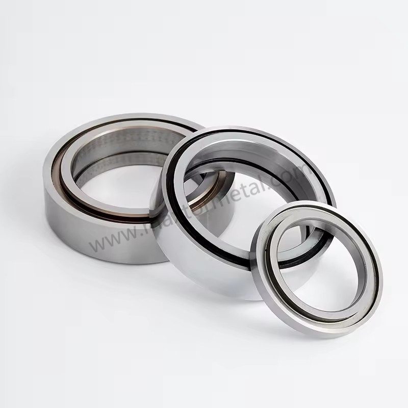
Once mechanics are stable and measurement is in place, you can optimize overlap depth and side clearance like any other process window problem.
DOE to map the design space
A practical DOE for converting looks like:
- Factors: overlap depth, side clearance/side load, speed (optional), tension (optional), knife condition (new vs mid-life).
- Responses: edge quality score, torque/current, temperature rise, dusting proxy, changeover time.
Keep it tight:
- Use a small factorial or central composite design to cover the space without exploding trials.
- Randomize run order where feasible to reduce drift bias.
Surrogate modeling (RSM/GP)
The goal of a surrogate model is to predict responses between tested points.
- Response surface methods (RSM) are simple and interpretable. They work well when the response is smooth.
- Gaussian process (GP) models are more flexible when you suspect nonlinearities (common in cutting due to threshold effects).
You don’t need to publish the math to get value. What you need is a model that helps answer: “If I move overlap down slightly and open clearance slightly, will I still meet edge spec without overheating?”
Multi-objective Pareto trade-offs
In the real world you’re balancing at least two objectives:
- maximize edge quality
- minimize load/temperature (proxy for wear and downtime risk)
Use a Pareto view to pick operating points that aren’t dominated by another setting.
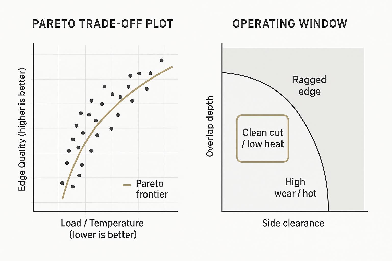
Worked example (illustrative, not universal)
Below is a simplified example of how a team might translate the workflow into an actionable setup window. Numbers are intentionally generic—use your own machine limits and material specs.
대본
- Line: high-speed slitter/rewinder
- Web: film or paper-grade web where edge defects show up as burr/feathering and dusting
- Objective: meet edge spec while minimizing drive load and temperature (proxy for wear)
Step1 — Choose starting bounds
- Start within your documented safe setup limits.
- Use published starting windows (when available) only as bounds, then narrow them based on your machine’s runout, holder stiffness, and the substrate’s behavior.
Step2 — Define what you will measure on every trial
- Edge quality score (use a consistent rubric)
- Drive current/torque at steady state
- Temperature rise at the knife area (IR spot check or thermal camera)
- Notes on dusting/lint and any audible rubbing
Step3 — Run a small 2×2 DOE (fast learning with minimal trials)
Choose two levels for each factor and keep speed/tension fixed during the trial block.
- Factor A: overlap depth → Low / High
- Factor B: side clearance (or controlled side load) → Low / High
Record responses after the process stabilizes at the same time-in-run.
Step 4 — Pick a Pareto-balanced point
- Eliminate any settings that fail the edge spec.
- Among the remaining settings, prefer points with lower torque/current and lower temperature rise.
Step 5 — Validate robustness
- Recheck the chosen point at the top and bottom of your real tension window.
- Repeat with a mid-life knife condition to ensure the window holds as the edge rounds.
The takeaway is not the specific numbers—it’s the discipline: small, controlled changes + repeatable measurements + a documented decision rule.
Quantified field case (paper converting, anonymized)
The following data comes from Maxtor Metal project support for an anonymized paper manufacturer. The customer name has been anonymized.
Context
- Industry: paper converting / rewinding line for coated printing paper
- Material: lightweight coated paper (LWC) for packaging inserts and labels
- Basis weight: 60–90 g/m²
- Thickness: ~55–95 μm
- Surface and fillers: clay-coated surface; calcium carbonate filler
- Notes: abrasive dust generation at higher speed; sensitive to edge fuzz and fiber pull-out
- Equipment: duplex rewinder with a shear slitting section
- Trial speed range: 900–1400 m/min (max line speed 1800 m/min)
- Knife holders: pneumatic shear knife holders; dished top knives + bottom anvils
- Web tension: 80–140 N (varies with roll diameter)
Initial symptoms and baseline scoring
At speeds above 1200 m/min, the line showed paper dust accumulation, fuzzy slit edges, occasional feathering, and unstable knife life between shifts.
Operator scoring system (1–10 severity):
- Dust generation: 8/10
- Edge fuzz: 7/10
- Cut stability: 6/10
Note on method: There is no single, universally adopted ISO/TAPPI/ASTM standard that mandates a 1–10 severity score for slitting defects. In practice, plants commonly use a documented internal visual severity scale (with training and reference photos) and, where needed, cross-check it against standardized test methods. For paper cut-edge raggedness, ISO 22414 (Paper — Cut-size office paper — Measurement of edge quality) provides a repeatable, template-based ordinal edge-quality rating approach that can be used as a reference framework when defining severity anchors for fuzz/feathering.
A previous attempt increased overlap aggressively to reduce fuzz, but it increased heat generation and accelerated knife wear in less than one production shift.
Settings before and after
Original settings
- Overlap: 0.9–1.1 mm
- Side clearance / side load: relatively high pneumatic loading (estimated 5–6 lbf equivalent contact pressure)
Observed issues during long runs: excessive friction, polished/glazed knife edge, and rising dust generation.
Optimized settings (after multiple production trials)
- Overlap reduced to: 0.45–0.65 mm
- Side clearance / side load adjusted to a lighter, more stable contact condition
- Cant angle slightly reduced
- Bottom knife overspeed stabilized at ~5%
결과
| 미터법 | Before optimization | After optimization |
|---|---|---|
| Edge quality severity score | 7/10 | 2–3/10 |
| Dust severity score | 8/10 | 3/10 |
| Scrap / rejected rolls | 4–6% | 1.5–2.5% |
| Knife change frequency | every 1–2 shifts | every 3–4 shifts |
| Average knife life | baseline | +40–60% |
| Unplanned slitting stops | frequent during long runs | reduced by ~50% |
Conditions behind the data
- Knives reground and polished before trials
- Holder bearings verified before setup
- Stable web tension control
- Spacer/contact surfaces cleaned each shift
- Measurements compared only after thermal stabilization of the slitting section
Constraints and robustness
Material variability and abrasion
Your “optimal” point can fail when the material changes.
Common variability sources:
- thickness and coating variability
- filler/abrasive content (wear rate changes)
- humidity and static effects that change web behavior
Robustness tactics:
- Validate at the upper and lower bounds of your real material spec.
- Track knife life by material lot when abrasion is high.
Machine limits and alignment
You can’t optimize past mechanical limits.
Constraints to document explicitly:
- maximum achievable alignment/runout
- holder stiffness and repeatability
- safe side load limits for bearings and shafts
If your runout is large, the model will “recommend” a wider clearance just to survive oscillation. Fix the mechanical root cause first. When overlap and clearance optimization doesn’t resolve the drift—because the root cause lies in tension imbalance, machine alignment, or air dynamics rather than knife geometry—a systems-level diagnostic approach covers all four subsystem categories. See Stopping Snake Cuts in Film Slitting: A Systems Checklist.
For a detailed treatment of runout measurement and cold-to-hot verification, see our companion guide on Axial Runout and Edge Quality.
For the bore-level root cause—how ISO 286 fit selection and bore-to-OD coaxiality control translate into assembled TIR—see 중앙 내경 공차 및 런아웃: 고속 슬리터 나이프의 ISO 286 적합성 최적화.
On adhesive-coated webs — PSA tape, protective film, label stock — overlap and side-load settings also directly control adhesive transfer rate and blade buildup frequency. For the setup parameter windows, heat-contact feedback mechanism, and layered diagnostic logic specific to these constructions, see 원형 슬리팅 날의 점착물 축적: 열 접촉 피드백, 코팅 선정 및 계층적 진단 프로토콜.
Wear, drift, and control plans
Optimization isn’t a one-time event. Overlap and clearance drift with wear, thermal growth, and rebuilds.
Control plan elements:
- baseline settings for new knives and mid-life knives
- re-check triggers (torque trend threshold, temperature threshold, edge-score drop)
- inspection frequency and sign-off roles
This is also where supplier process control matters. Maxtor Metal positions its circular knives around strict in-process checks (incoming material inspection, first article, in-process, final inspection) and measurable verification such as runout checks and hardness mapping. Shipping documentation and customs coordination support is available for international orders, which reduces the risk of late replacements disrupting production schedules.
Deployment checklist
Pre-DOE calibration
- Confirm knife condition and geometry are within spec (no chips, consistent bevel).
- Verify alignment and runout; document the measurement method.
- Lock down “constant” variables (web path, tension window, speed band) for the DOE.
During-DOE controls
- Change only the planned factors; record the actual achieved settings.
- Use the same edge inspection method and scoring rubric each run.
- Capture torque/current and temperature at the same time-in-run (steady state).
Post-DOE SOP and monitoring
- Publish the chosen overlap/clearance operating window (min/target/max).
- Define drift triggers (torque rise, temperature rise, edge-score drop) and actions.
- Build a changeover checklist so settings are repeatable across shifts.
Applicability and limits (when to validate more carefully)
The workflow in this article is intended for rotary knife slitting where overlap and side clearance can be measured and controlled. In the following conditions, validate more conservatively and resolve upstream issues before you “tune overlap”:
- Ultra-thin or low-stiffness webs: increased risk of wrinkling, stretching, and unstable slit width. Reduce the trial step size, confirm tension control, and validate at production speed.
- High filler / abrasive grades: accelerated edge wear can shift the operating window quickly. Monitor torque and temperature trends more frequently and track knife life by material lot.
- Static electricity and humidity-driven variability: dusting, lint, and web handling can change day-to-day. Stabilize humidity control and static mitigation before attributing defects to overlap/clearance.
- High radial/axial runout or poor alignment: overlap and clearance may oscillate each revolution, causing periodic defects. Correct runout/alignment first; otherwise DOE results may not generalize.
If these limits apply, treat any “optimal” setting as provisional until it holds across your full tension and speed window.
Safety note (read before adjusting knives)
Slitting and knife setup can be hazardous. Follow your site’s procedures and the machine manufacturer’s guidelines.
- 사용 lockout/tagout (LOTO) before any adjustment, inspection, or cleaning.
- Wear appropriate PPE (cut-resistant gloves, eye protection, and other site-required protection).
- Treat knives, holders, and nearby components as potential hot surfaces after running; verify temperature before handling.
- Keep hands clear of pinch points and rotating parts on slitter/rewinder systems; never reach into the web path while the line is energized.
- Do not exceed the machine’s allowable limits for overlap/penetration, side load, or pressure. When in doubt, start at the low end of your window and validate step-by-step.
This article provides general engineering guidance; validate final settings on your equipment and material.
결론
Optimal overlap depth and side clearance don’t just “improve the edge”—they stabilize the whole slitting system: lower heat, slower wear, fewer web breaks, and fewer unplanned changeovers. When you treat these settings as measurable variables, and use DOE plus a Pareto trade-off to choose a robust operating window, you can move faster with less scrap and less downtime.
If you want repeatable results across shifts and plants, Maxtor Metal recommends keeping the workflow simple: verify the knives and tooling (runout, hardness consistency, documented inspections), then use a control plan to catch drift early.
The quickest path to adoption is simple: validate the starting windows on representative materials at real speed/tension, then monitor torque and temperature trends to keep the setup inside the window as knives wear.
FAQ
What is overlap depth in shear slitting?
Overlap depth is how far the top circular knife intersects below the tangent of the bottom knife at the cut point. Too little overlap can open the cut point and cause unstable separation; too much overlap increases contact length and friction.
What is side clearance on a circular knife slitter?
Side clearance is the axial/lateral gap (or effective engagement) between the upper and lower knives that determines how the knives stay engaged under load. Excess clearance can lead to bending/stretching at the edge and burrs; too little clearance can cause rubbing, heat, and micro-chipping.
How do I know if overlap depth is too high or too low?
Too low often shows up as incomplete separation, tearing, or intermittent edge defects. Too high typically shows as faster dulling, more heat at the knife, and sometimes web distortion or dusting.
Why does tighter clearance sometimes make the edge worse?
Because very tight clearance can force metal-to-metal rubbing and raise temperature. That heat accelerates wear and can create micro-chips, which then produces a rougher edge even though the knives are “closer.”
What overlap depth and clearance should I start with for film slitting?
Start with conservative overlap and the minimum side engagement that keeps the cut stable, then adjust in small increments while inspecting the edge at production speed. The exact window depends on thickness, polymer type, coatings, and machine stiffness.
For adhesive-backed films where coating build-up on knife faces shifts the effective clearance over a run, surface coating selection interacts directly with your clearance window. A diagnostic framework for choosing between DLC and PTFE coatings based on whether your failure mode is wear-limited or transfer-limited is covered in DLC vs PTFE Coatings for Slitting Blades: Engineer’s Guide.
What measurements matter most when optimizing circular knife settings?
The most actionable signals are repeatable edge-quality scoring, torque/drive current trends, temperature checks, and runout/alignment verification. If you can trend those four, you can usually detect drift before scrap and downtime spike.
How do DOE and Pareto optimization help in slitting setup?
A DOE maps how overlap and clearance affect edge quality, torque, and temperature across a defined range. Pareto analysis then helps you pick settings that improve edge quality without paying for it with excessive heat and wear.
Where can I find circular knives designed for film, paper, and nonwoven converting?
Maxtor Metal’s circular knives and blades product page summarizes common applications, material options, and quality verification methods that are relevant when you’re trying to hold a tight operating window.
Jerry Chu 입니다 Technical Support Specialist in Maxtor Metal’s 애프터 서비스 team, with 10 years of cross-industry application experience spanning paper converting, plastic recycling/granulation, metal slitting, and wood processing. He helps plants troubleshoot real-world slitting issues such as cutting burrs, excessive dusting, and shortened knife life through setup validation, measurement discipline, and practical process windows.
자격증: PMP, CMRP
At the end of the day, stable slitting is controlled geometry plus controlled verification—exactly the mindset Maxtor Metal builds into both knife manufacturing and the supporting documentation you need for traceability.
참고문헌
[1] “Experimental Research on Sheared Edge Formation in the Shear-Slitting Process.” PMC (peer-reviewed, open access). https://pmc.ncbi.nlm.nih.gov/articles/PMC9784500/
[2] Khonsari, M. M., & Booser, E. R. Applied Tribology: Bearing Design and Lubrication. Wiley.
[3] ISO 22414. Paper — Cut-size office paper — Measurement of edge quality. https://www.iso.org/standard/82031.html
[4] ISO 15359. Paper and board — Determination of coefficient of friction. https://www.iso.org/standard/27374.html
[5] TAPPI T 494. Tensile properties of paper and paperboard (using constant rate of elongation). https://imisrise.tappi.org/TAPPI/Products/01/T/0104T494.aspx
[6] TAPPI T 411. Thickness (caliper of paper, paperboard, and combined board), Test Method. https://imisrise.tappi.org/TAPPI/Products/01/T/0104T411.aspx
[7] ASTM D828. Standard Test Method for Tensile Properties of Paper and Paperboard. https://www.astm.org/d0828-16e01.html

 English
 Spanish
 Italian
 French
 Portuguese
 Russian
 German
 Arabic
 Hindi
 Vietnamese
 Indonesian
 Japanese
 Korean