Quick answer: 수링 펠릿타이저(water-ring pelletizer) 나이프 블록은 다음 4가지를 검증하여 대규모 생산 적격 판정을 받습니다: 기능적 데이터에서의 런아웃/TIR(일반적으로 ≤0.03–0.04 mm), ISO 21940 기준 밸런스 등급(기본 G6.3, 고속 주행 시 G2.5로 상향 조정), ISO 20816 기준 진동 허용치(일반적으로 ≤2.8 mm/s RMS), 그리고 시리얼 번호와 연동된 EN 10204 3.1/3.2 인증서를 통한 완전한 재료 추적성.
대규모 폴리머 공장은 나이프 블록의 "마모" 자체보다는 그로 인해 발생하는 계획되지 않은 가동 중단(unplanned stop)으로 밤잠을 설칩니다: 진동 이상, 다이 페이스 손상, 펠릿 품질 저하, 그리고 감사(audit)를 통과하지 못하는 QA 기록이 바로 그 원인입니다.
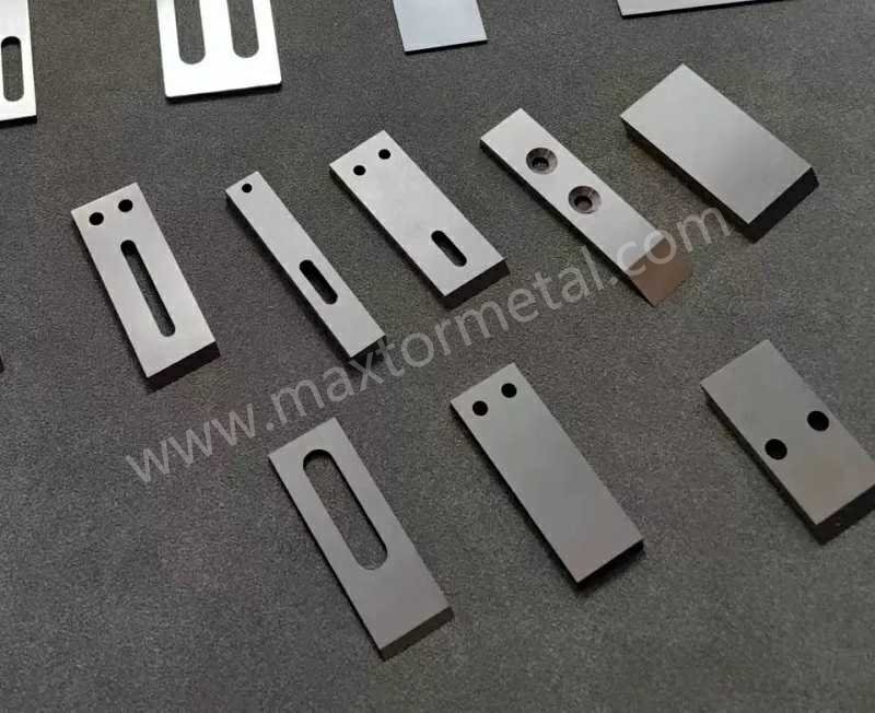
나이프 블록의 엔지니어링 자격 평가가 단순한 문서 작업이 아니라 리스크 관리인 이유가 바로 여기에 있습니다. Maxtor Metal의 평가 접근 방식은 단순한 주장이 아닌 증거를 기반으로 합니다: 도면, 추적성, 검사 기록, 그리고 반복 가능한 인수 테스트가 그 핵심입니다. 실질적인 측면에서 나이프 블록 자격 평가란, 특정 나이프 블록이 전체 RPM 범위에서 펠릿 품질 저하 없이 안정적으로 작동함을 측정과 문서를 통해 증명하는 것을 의미합니다.
For readers who want a concrete reference point for die-face, underwater, and water-ring knife terminology — including material grades, bevel geometry, and operational RPM boundaries — see Maxtor Metal’s pelletizer knives product page.
- Why knife block qualification matters on High-Volume Petrochemical Production lines
- Scope: BKG/Coperion die-face water-ring pelletizers, 1000–4000 RPM, zero-defect delivery
- How this spec aligns with plant QA, reliability, and audit expectations
A knife block sits at a high-energy interface: rotating hardware, thermal gradients, water-loop disturbances, and tight clearances at the die face. In that environment, the cost of a “close enough” component is rarely the part itself—it’s the secondary damage and the time to recover stable pellet quality.
A qualification spec gives QA and reliability a shared language. It also gives procurement something measurable to buy against: tolerances, certificates, calibration controls, and a defined release dossier.
속도 안정성 (1000–4000 RPM)
At 1,000–4,000 RPM, small geometric errors can become large process symptoms: unstable cutting, fines/angel hair, high bearing loads, and fast wear. The goal of this section is not to name every possible tolerance, but to define a short list that correlates strongly with stable operation.
Runout, parallelism, and clearance
What you are trying to prevent: intermittent contact at the die face, uneven knife loading, and localized heat generation that shows up as pellet strings, smearing, or agglomeration.
A practical acceptance approach is to define:
- Runout (TIR) at functional datums (e.g., bore, mounting face, assembled knife track)
- 병행 between critical faces that control clamp load distribution
- Clearance window that accounts for thermal growth and assembly stack-up
Typical acceptance targets used in practice (must be tied to the plant drawing and measurement method):
- Total indicator runout (TIR) at the relevant datum(s): ≤ 0.03–0.04 mm
- Flatness/parallelism at clamp and reference faces: controlled to avoid knife “rocking” under load
- Documented clearance setting method (feeler gauges / shims / calibrated spacers) with recorded values
Measurement setup notes (to avoid arguing about numbers):
- Define the datum(s) used for TIR (bore vs mounting face vs assembled knife track) and keep the same setup for cold vs hot recheck.
- State the indicator resolution and how the part is supported (between centers / on V‑blocks / in machine).
- Record the assembly condition (knife block only vs fully assembled with knives + fasteners) and the tightening sequence/torque.
- For acceptance, require a short “setup photo or sketch” in the inspection record so future repeats are comparable.
핵심 요점: For water-ring pelletizing, the reliability question isn’t “is the part within tolerance?” It’s “will it stay within the tolerance window once it sees heat, clamp load, and RPM?”
Balancing grades and methods (ISO 21940)
Knife blocks live in rotating assemblies where balance quality directly impacts vibration, bearing life, and cut stability.
Balance requirements should be expressed in two ways:
- Balance quality grade (your target tolerance)
- Method and configuration (what was actually balanced—component vs assembled stack)
A common pattern for qualification is to start with a baseline requirement (e.g., G6.3) and tighten to G2.5 where the application and speed demand it.
- ISO 21940-11:2016 defines procedures and tolerances for balancing rigid rotors and is typically referenced for balance-grade language and verification expectations: ISO 21940-11:2016.
- For many teams, the “practical” expectation is that the final balancing record indicates:
- balancing machine type and calibration status
- correction plane(s)
- residual unbalance achieved
- configuration (knife block alone vs knife block + fasteners + knife set)
Done when: your dossier includes the balancing report and the drawing revision it was balanced to.
Worked example: translating ISO 21940 balance grade (G) into an allowable residual unbalance
To keep balance requirements actionable, many teams add a worked example that converts a chosen balance quality grade (G) into an allowable residual unbalance for a given rotor.
A commonly used relationship is:
- Permissible specific unbalance: e_per = G / ω
- Angular speed: ω = 2π × n / 60 (rad/s), where n is RPM
- Permissible residual unbalance (per correction plane): U_per = e_per × m, where m is rotor mass (kg)
Example (illustrative — use your real mass and speed):
- Target grade: G2.5
- Operating speed: 3,000 rpm → ω ≈ 314 rad/s
- Rotor mass (knife block + fasteners + knives as balanced): 12 kg
Then:
- e_per = 2.5 / 314 ≈ 0.00796 mm
- U_per = 0.00796 mm × 12 kg ≈ 0.0955 kg·mm (≈ 95.5 g·mm)
Done when: the balance report states the grade, operating speed basis, rotor mass basis, correction plane(s), and the achieved residual unbalance versus the allowable value.
Vibration acceptance (ISO 10816/20816)
Vibration acceptance should be defined as a measured condition, not a vague “runs smoothly.” That means:
- measurement locations (bearing housing / machine casing)
- sensor type and mounting
- operating speed/load condition
- acceptance threshold and escalation rule
ISO guidance is commonly applied as a zone concept (A–D) for overall velocity RMS measured on non-rotating parts. The current series used for many industrial machines is ISO 20816; for example: ISO 20816-3:2022.
In plant specs, it’s common to see a conservative “green band” limit such as ≤ 2.8 mm/s RMS used as an acceptance target for stable long-term operation—but this must be aligned to the applicable machine group and measurement setup.

Measurement setup notes (make the limit meaningful):
- Where to measure: specify the exact location (e.g., bearing housing in radial direction on the drive/non‑drive end) and keep it consistent for baseline vs acceptance.
- Sensor & mounting: accelerometer vs velocity probe, stud vs magnetic base, cable routing, and mounting torque can change readings.
- Frequency band: record the band used (e.g., 10–1000 Hz as a typical overall band). If you use a different band, state it.
- Machine grouping: align the limit to the applicable ISO 20816 machine group / support condition and document the rationale.
Safety / YMYL note: Vibration limits are not “universal pass/fail” numbers. The acceptance threshold must be reviewed and signed off by the responsible rotating-equipment engineer for your specific machine class, sensor location, and operating condition.
Done when: vibration readings at 1,000–4,000 RPM are documented, repeatable, and traceable to a calibrated instrument.
In short: runout, parallelism, and balance grade are the three checks that determine whether a knife block stays stable from 1,000 to 4,000 RPM.
재료 및 추적성
When knife blocks are treated as critical consumables, traceability becomes part of reliability. The point is not to collect certificates—it’s to be able to answer, months later, exactly what material went into which serial number, and what verification was performed.
EN 10204 MTCs and heat/lot linkage
A baseline expectation for metallic products is an inspection certificate per EN 10204.
- Type 3.1: manufacturer inspection certificate with specific inspection results.
- Type 3.2: the same, but with independent verification/countersignature by purchaser/third party.
For a standards-catalog reference: BSI — BS EN 10204:2004, Metallic products — Types of inspection documents.
Done when: the MTC is linked to the knife block serial number, heat/lot, and purchase order line item.
Hardness and coatings (ASTM E18/B487/B499/B571)
Hardness and coating controls only work if the test method is specified.
- Hardness (Rockwell): ASTM E18 (Rockwell hardness of metallic materials)
- Coating thickness verification methods (select based on coating/substrate and whether destructive testing is allowed):
Done when: hardness/coating results are recorded against the part serial number, and the measuring equipment is in calibration.
Marking/serialization and packaging controls
Traceability fails most often at the handoff points: mixed lots, reworked parts without re-identification, packaging damage, or paperwork separated from the part.
Minimum controls typically include:
- permanent serial/heat mark at a defined location that does not compromise function
- packaging labels that repeat: PO, drawing revision, serial(s), heat/lot, quantity
- segregation rules for nonconforming or reworked items
In short: traceability isn’t about collecting certificates—it’s about being able to link any knife block’s material, hardness, and coating data to a specific serial number months after delivery.
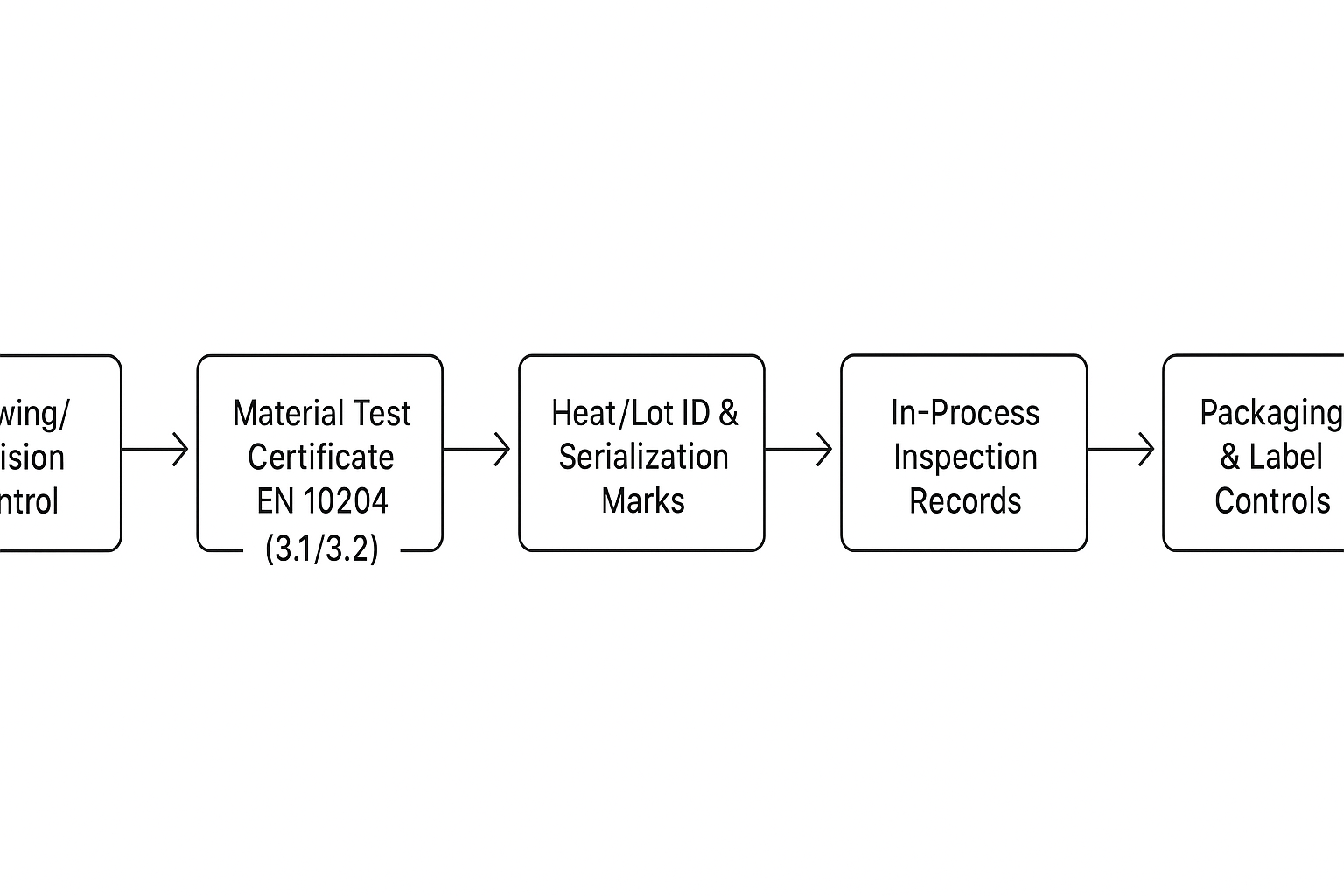
자격 평가 워크플로우

Treat qualification as a repeatable workflow with explicit checkpoints. The goal is to avoid “passing cold, failing hot,” or balancing that is invalidated by final assembly.
Cold checks and pre-balance
Input: drawing + revision, inspection plan, calibrated gauges.
Actions:
- dimensional inspection at functional datums (bore, faces, knife track)
- runout verification with a defined setup (fixture and indicator locations)
- pre-balance as a component where applicable (and record configuration)
Output: cold inspection report + preliminary balance record.
Done when: deviations are either corrected under controlled rework or formally dispositioned.
Thermal soak and hot recheck
Thermal growth and stress relief can move what looked “perfect” on the bench.
Input: cold-qualified component + thermal soak protocol.
Actions:
- soak at representative temperature (time and setpoint defined by the plant)
- recheck runout/parallelism at the same defined datums
- confirm the clearance-setting method still holds the intended window
Output: hot inspection addendum with before/after measurements.
Done when: hot values stay inside the tolerance window without forcing assembly adjustments.
Production trial and pellet QA correlation
The production trial should connect mechanical acceptance to the metrics the plant actually cares about.
Input: qualified assembly + trial plan (resin, throughput, RPM range, water-loop conditions).
Actions:
- run at low/mid/high speeds in the operating band
- record vibration and any process disturbances (water temperature/flow instability, die pressure behavior)
- correlate knife block condition to pellet QA: pellet length distribution, fines/angel hair trend, and any die-face buildup observations
Output: trial report that ties measured mechanical condition to pellet outcomes.
Done when: pellet QA stays stable across the operating band without abnormal vibration or accelerated wear.
Documentation practice: In audits and supplier qualification reviews, teams check whether a supplier can package these checkpoints into a coherent dossier. Maxtor Metal’s release process for knife block components is built around this structure—material certificates, balance records, and inspection traceability tied to each serial number—which is what an audit-ready dossier looks like in practice.
Anonymized plant example: how TIR and vibration correlate with pellet QA stability
The following anonymized example shows how tightening the knife block face TIR and standardizing assembly practice can move both vibration and pellet quality in a high‑volume HDPE line.
Process context (held constant during validation):
- Pelletizer type: high‑capacity water‑ring system (similar class to Gala / Maag / Automatik)
- Polymer: HDPE, MFI ~ 0.3–0.8 g/10 min
- Throughput: 14–18 t/h
- Knife block speed: 2,900–3,300 rpm
- Cutting water: 80–90°C, closed loop
Before vs after (90‑day observation; 6 batches / ~310 t vs 18 batches / ~970 t):
- Knife block face TIR: 0.072 mm → 0.018 mm (dial indicator, after installation, 360° sweep)
- Rotor assembly TIR (cold): ~0.060 mm → ~0.015 mm
- Bearing housing vibration overall (10–1000 Hz): ~4.5 mm/s RMS → ~1.7 mm/s RMS
- Peak acceleration: 10–13 m/s² → 3–5 m/s²
- Fines: ~0.8 wt% → ~0.28 wt% (online sieving)
- Stringers: ~4–6 occurrences/ton spot checks → largely eliminated (only isolated samples)
- Pellet length CV:~±8% →~ ±3% (image analysis, >1000 pellets)
- Oversized pellets (>1.5× target length): ~1.6% → ~0.3% (vision inspection)
- Unplanned stops: ~every 18 days → none observed over a multi-month tracking window
- Knife change interval: ~12 days → ~28 days (same quality requirement)
Observed failure mode (first attempt did not fully work):
The first correction only reground the knife‑block mounting face.
- Face TIR improved to ~0.048 mm
- Vibration improved only to c3.6 mm/s RMS
- Fines stayed ~0.65 wt%
Root cause found during teardown: mild wear on a locating surface plus inconsistent bolt tightening order caused slight cocking during clamp‑up.
Measurement sequence used by the engineering team:
- Measure spindle taper and mounting flange runout.
- Install knife block (no knives) and record face TIR.
- Install knives and tighten to spec torque; re‑measure TIR.
- Low‑speed run (~300 rpm) check.
- Ramp to production speed (~3,000 rpm) and record vibration RMS.
- Collect pellets for 2 hours (sampling every 30 minutes) to trend fines and length distribution.
- Track stability over 3 production months.
Assembly practice that improved repeatability:
- Use a star pattern torque sequence: 30% → 60% → 100%
- After final torque, re‑measure face TIR; target repeatable ≤ 0.02 mm
메모: This example is constructed from typical field patterns to illustrate how TIR and vibration improvements correlate with pellet QA outcomes; it is not a single customer’s raw inspection record. Your absolute thresholds must still be tied to your machine design, measurement setup, and plant QA acceptance plan.
In short: a knife block isn’t qualified until it has passed cold inspection, held its tolerances after thermal soak, and proven stable pellet QA in a production trial—skipping any one step leaves a gap between bench numbers and plant performance.
QA 문서 및 제로 결함 납품
A “zero-defect” expectation is enforced through a release dossier that makes receiving inspection faster and makes NCR handling cleaner.
FAI and PPAP-like submission package
Even if you don’t run formal automotive PPAP, the idea of a structured first-article package is transferable.
A practical submission pack includes:
Practical templates (what to include so the dossier is audit-ready)
To make supplier qualification repeatable, define the fields you expect in each record. Even if you don’t publish a downloadable template, this checklist reduces back‑and‑forth.
- FAI / dimensional report
- ballooned drawing revision, datums used, gauge IDs & calibration dates
- runout/flatness/parallelism results with setup sketch/photo reference
- acceptance/disposition signature
- Balancing record
- grade (e.g., G6.3 / G2.5), speed basis, rotor mass basis, correction planes
- achieved residual unbalance, machine ID & calibration status
- configuration balanced (component vs assembled stack)
- Thermal soak / hot recheck addendum
- soak temperature/time, fixture method
- before/after values at the same datums
- confirmation of clearance-setting method and final window
- Production trial report
- resin family, throughput, RPM points, water loop conditions
- vibration readings (location + band), observed disturbances
- pellet QA metrics (fines, stringers, length distribution) + sampling plan
- NCR / CAPA pack
- symptom, containment, root cause, corrective action, verification plan
- re-identification/segregation records for reworked parts
Done when: a receiving inspector can verify identity + acceptance in minutes, and an auditor can trace every critical result to a calibrated measurement system.
- drawing + revision history
- dimensional inspection report (FAI-style ballooned drawing, where applicable)
- balance report (grade, machine, configuration)
- material certificates (EN 10204 3.1/3.2) with heat/lot linkage
- hardness/coating reports (method identified)
- packing list with serials and inspection status
Incoming inspection and calibration (ISO 2859-1/ANSI Z1.4, ISO/IEC 17025)
Incoming inspection should be risk-based: critical dimensions and identity checks are 100%; lower-risk characteristics can be sampled.
- Attribute sampling schemes are commonly based on ISO 2859-1 (and aligned with ANSI/ASQ Z1.4 practices in the US): ISO 2859-1.
- Calibration competence is commonly referenced against ISO/IEC 17025, especially when measurements are used to release product: ISO/IEC 17025:2017.
Done when: the plant can prove the measurement system is controlled (calibration status, traceability, records retention).
NCR/CAPA management and release documentation
The dossier should also define what happens when something is off.
Minimum expectations:
- NCR format (symptom, containment, disposition)
- CAPA expectations for repeat issues (root cause and corrective action)
- release documentation that clearly states acceptance and any approved deviation
In short: zero-defect delivery is enforced by a release dossier, not a promise—if a receiving inspector can’t verify identity and acceptance in minutes, the dossier isn’t complete.
모니터링 및 재평가
Knife blocks don’t fail only from initial defects. They drift—through wear, regrinds, water chemistry, and process changes.
Baseline trending and vibration/runout limits
Set a baseline at commissioning and trend against it:
- vibration baseline at key RPM points
- runout baseline at defined datums
- pellet QA baselines (fines/angel hair, pellet length spread)
Define an escalation rule: “investigate at X,” “stop and correct at Y.”
Requalification triggers and intervals
Common triggers:
- major maintenance event (bearing replacement, shaft work)
- repeated pellet-quality excursions that correlate with vibration/runout drift
- change in resin family or filler loading that changes cutting load
Set an interval that matches your risk tolerance (e.g., per turnaround, per knife-life multiple, or per defined runtime).
Change control and deviations
Any change that can affect rotating behavior or clamp/clearance should be controlled:
- drawing revision changes
- material substitution
- heat treatment route changes
- coating supplier/process changes
Deviations should be time-bound and documented with risk assessment and sign-off.
In short: knife blocks drift through wear and process changes, so a fixed acceptance test at commissioning isn’t enough—baseline trending and defined requalification triggers are what catch the drift before it causes downtime.
결론
- Key acceptance numbers and verification steps to enforce consistency
- How this framework reduces downtime and supports audit readiness
At a practical level, the acceptance criteria that do most of the reliability work are simple and measurable:
| 매개변수 | Typical acceptance target | Standard reference |
|---|---|---|
| Runout (TIR) at functional datum | 0.03–0.04 mm | Plant drawing + ISO measurement practice |
| Balance grade | G6.3 baseline → G2.5 at higher speed | ISO 21940-11:2016 |
| Vibration (overall RMS) | ≤ 2.8 mm/s (plant-defined, machine-class dependent) | ISO 20816 |
| 자재 추적성 | MTC linked to serial/heat/lot | EN 10204 Type 3.1 / Type 3.2 |
Wrap those numbers in a workflow (cold check → balance → hot recheck → trial correlation) and a dossier (certs, calibration, release records), and qualification becomes enforceable—not interpretive. This is the standard Maxtor Metal applies to knife block components: documentation quality as part of engineering quality, not an afterthought.
For the full engineering specifications — including metallurgical classifications, bevel angle selection, heat treatment protocols, and application matrix across polymer types — see Maxtor Metal’s pelletizer knife specifications and material grades.
CTA: 자격 평가 문서 검토 요청
If you want to reduce qualification risk quickly, share your drawing (or photos + key dimensions) and your acceptance targets (RPM range, balance grade, vibration method). A supplier review should come back with:
- proposed datum scheme and measurement setup
- balance plan (grade + configuration)
- traceability plan (MTC linkage + serialization)
- draft release dossier checklist (FAI, balance record, hot recheck, trial report)
Start here: Maxtor Metal — custom pelletizer knives and knife block components (ODM/OEM) with inspection traceability: https://maxtormetal.com/contact/
FAQ
수링 펠릿타이저(water-ring pelletizer)용 나이프 블록 자격 평가란 무엇입니까?
나이프 블록이 정의된 치수, 밸런스, 재료 및 문서 요구 사항을 충족하는지 검증하여, 펠릿 품질 저하나 2차 장비 손상 없이 운영 RPM에서 안정적으로 작동하도록 하는 프로세스입니다.
다이 페이스(die-face) 펠릿타이저 나이프 블록에는 어느 정도의 런아웃(TIR)이 허용됩니까?
많은 공장에서 특정 기능 데이터에서 0.03–0.04 mm TIR 정도를 허용 목표로 설정하지만, 올바른 제한치는 기계 설계, 측정 설정 및 다이 페이스에서 필요한 간극에 따라 다릅니다.
펠릿타이저 나이프 블록은 어떤 밸런스 등급을 충족해야 합니까—G6.3 또는 G2.5?
G6.3은 일반적인 회전 부품의 기본값으로 자주 사용되며, G2.5는 고속에서 더 높은 안정성이 필요할 때 사용되는 더 엄격한 요구 사항입니다. 적절한 등급은 RPM, 로터 질량 및 공정이 진동에 얼마나 민감한지에 따라 결정됩니다.
2.8 mm/s RMS는 보편적인 진동 제한치입니까?
아니요. 2.8 mm/s RMS는 구역 지침에 맞춘 실용적인 허용 임계값으로 일반적으로 사용되지만, ISO 표준은 기계 그룹 및 측정 조건의 맥락을 사용합니다. 공장은 수락 계획(acceptance plan)에 기계 등급, 센서 위치 및 작동 조건을 명시해야 합니다.
EN 10204 3.1 재료 인증서란 무엇이며, 언제 3.2가 필요합니까?
3.1 인증서는 제조업체의 공인 검사 대표자가 발행하며 재료에 대한 구체적인 검사 결과를 포함합니다. 3.2는 더 높은 수준의 보증이 요구될 때 구매자의 검사관 또는 제3자에 의한 독립적인 검증/서명이 추가됩니다.
나이프 블록 부품의 경도와 코팅 두께를 어떻게 검증합니까?
事前に試験方法(例:ASTM E18に準拠したロックウェル硬さ試験)を定義し、コーティング/基材に基づいた適切なコーティング厚さ測定方法(断面顕微鏡観察、磁気式、または電解式)を選択します。また、破壊試験が可能かどうかも考慮します。
펠릿타이저 나이프 블록의 QA 문서(QA dossier)에는 무엇이 포함되어야 합니까?
최소 포함 사항: 도면 개정 관리, 치수 검사 결과, 밸런싱 보고서, 열/로트 번호가 연동된 재료 인증서, 경도/코팅 테스트 기록(측정 방법 명시), 측정 도구의 교정 상태, 그리고 출고 문서.
나이프 블록은 언제 재평가(requalification)해야 합니까?
일반적인 계기에는 주요 유지보수(베어링/샤프트), 반복적인 진동 또는 펠릿 품질 저하, 수지/충전제 로딩의 변화, 그리고 재료, 열처리, 코팅 또는 도면 개정에 대한 모든 제어된 변경 사항이 포함됩니다.
저자 및 기술 검토
제시 쉬 — Senior Quality Engineer, QA (Maxtor Metal)
- 15 years of experience in industrial blade quality and failure analysis
- 자격증: ASQ-CQE, ISO 9001 선임 심사원, ASNT 레벨 II
- Focus: differentiating failure modes (e.g., chipping vs low wear resistance) related to heat-treatment routes vs material segregation